Overview
This is the second tutorial in our Stairwell Pressurization series intended for Fire Protection Engineers who wish to perform Stairwell Pressurization analysis with Ventus as part of their Smoke Control projects. Continuing from the Closed Door Studies tutorial, this tutorial will demonstrate the Open Door case. You will learn how to apply our open door modeling methodology to the stairwell model, perform a transient analysis, and analyze the results of the pressurization study.
Before Starting
Before beginning this tutorial:
- Follow the Closed Door Studies tutorial to understand the basics of the model.
- Follow the Modeling Door States tutorial to understand how we recommend modeling doors in Ventus.
- Download the Stairwell Pressurization - Open Doors model to follow along.
Introduction
In the previous tutorial, we covered the modeling of a Closed Door Pressurization scenario for our stairwell model. This tutorial will cover the Open Door Pressurization case. As a reminder, here are the design criteria we will be designing to:
| Design Criteria | |
|---|---|
| Stairwell Doors Closed | |
| Differential Pressure at Doorways | 25-50 Pa |
| Maximum Applied Force at Doorways | 100 N |
| Stairwell Door Open at Fire Event Floor | |
| Minimum Flow Rate at Open Doorway | 1 m/s |
| Maximum time to achieve flow | 5 s |
In this scenario, we are interested in the latter requirements - achieving a \(1 \frac{m}{s}\) Flow Rate at an open door in the stairwell within 5 s of the door opening.
The Open Door Study
We will start this tutorial using the final state of the model from the Closed Door study.
This is the closed-door-study-4750.vnts model that you downloaded above.
We will modify the model to evaluate the Open door scenario.
To do this, we will need new Flow Elements in our model.
We will need to add:
| Flow Element | Use |
|---|---|
| Open Door | Modeling an open door in the Stairwell |
| Open Window | Modeling an open or shattered window on the Fire Event floor |
Once added, we will need to add additional Flow Paths to utilize these Elements, then re-run our study and make any necessary adjustments to the pressurization system.
Adding New Flow Elements
To add the new Flow Elements to the model:
- Use the Model › Edit Flow Elements action to open the Edit Flow Elements dialog.
- Click New….
- In the New Flow Element dialog, enter the name
Door-Openand select theOrifice AreaModel. - Click OK to create the Flow Element.
- In the Edit Flow Elements dialog for the
Door-Openelement, enter a Cross-Sectional Area of \(1.85 m^2\). - Click Apply to apply the changes to the flow element.
- Repeat the process to create another flow element named
Window, with the sameOrifice Areamodel, and a Cross-Sectional Area of \(0.8 m^2\). - Click OK to close the Edit Flow Elements dialog.
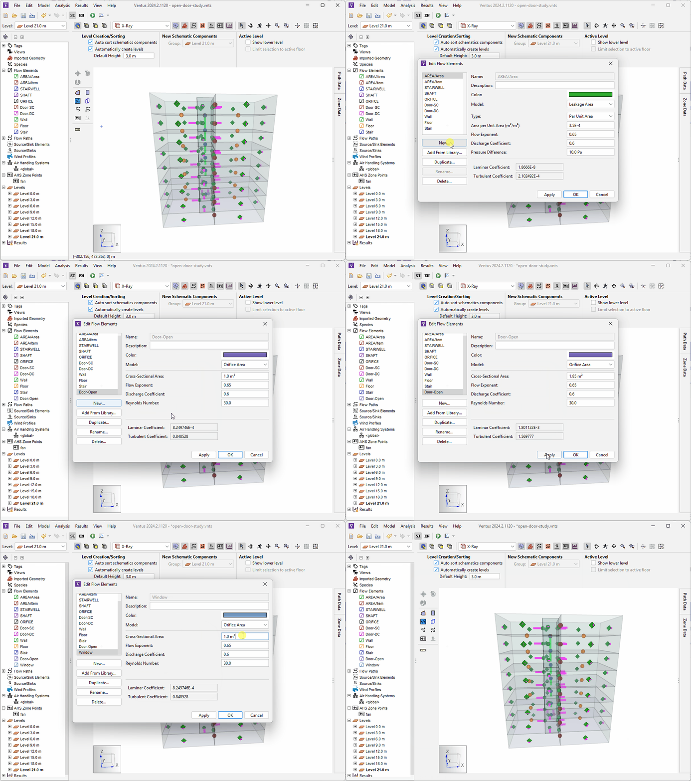
Now that we have the Flow Elements created, we need to create new Flow Paths on the event level to use them.
Create Flow Paths
Our Open Door scenario assumes that Level 12.0 m is the fire event floor.
TO model the fire scenario on this floor, we will modify the existing stairwell door Flow Paths on that level using our new Door-Open Flow Element and the modeling method described in our Modeling Door States tutorial to model a door opening at 30s and closing at 300s.
We will also add a Flow Path to each room that uses our new Window Flow Element.
The Door-Open Flow Paths will represent doors that are opened on the event floor for evacuations and firefighting actions, and the Window Flow Paths will represent windows that are either shattered due to heat, or opened for ventilation purposes.
First, we will add two Flow Paths to represent the windows. To do this:
- Right click
Level 12.0 min the navigation view and click Set as Active Level. - Click the
 icon to switch to the Top View.
 - Double-click the
 icon to select the Two Point Flow Path tool in pinned mode.
 - In the Tool Properties ribbon, select the
WindowFlow Element in the Element field. - Draw two lines across the outer walls of each Unit in the model to add the two new Flow Paths.
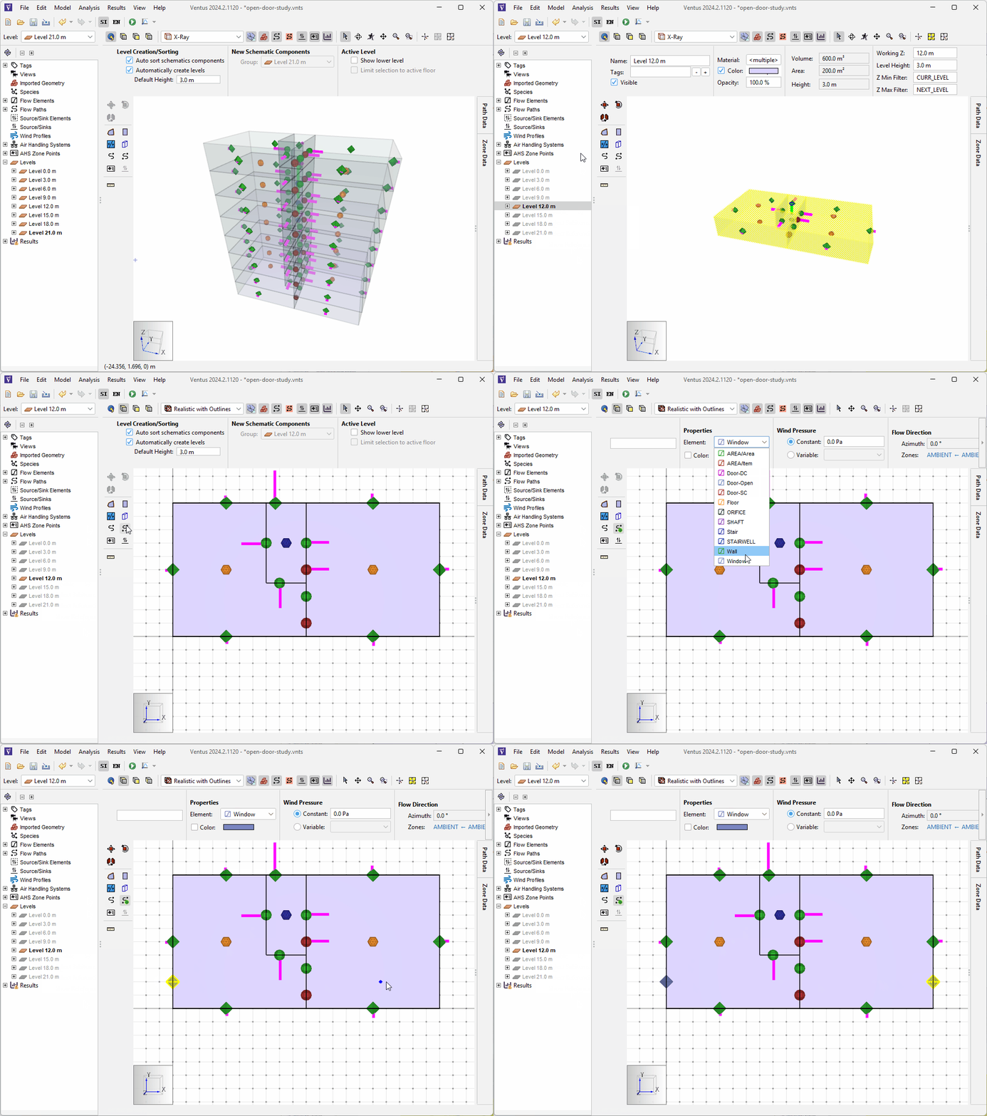
Window elementNow we will use the Modeling Door States method to model our open door.
The first step is to create our Door-Open Flow Path.
To do this:
- Click the
 icon to select the Two Point Flow Path tool.
 - In the Properties Ribbon, switch the Element field to use the
Door-Openflow element. - Draw a Flow Path on top of the existing
D2_1_3Flow Path (the red Flow Path connecting the stairwell to the right Zone). - In the Properties Ribbon for the Flow Path you just created, enter the name
D2_1_3_Openin the Name field.
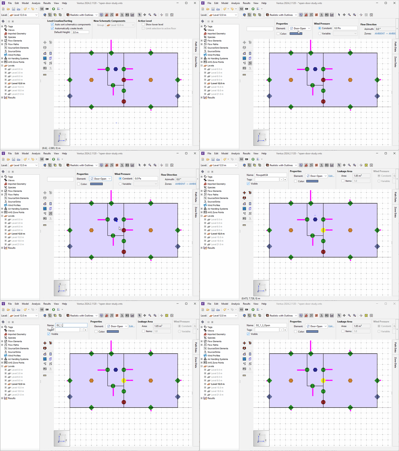
Door-Open element- Additionally, select the other Door Flow Path on the Event Level (
flowpath26_1_3) and select theDoor-OpenFlow Element in teh Element dropdown. This will model an additional open interior door on the event level.
We now have all of our Flow Paths created.
The final step of configuring our Flow Paths is to edit the Multiplier schedules so that the we can model the door being closed initially, opening at 30s, then closing again at 300s.
To do this:
- Select the
D2_1_3Flow Path in the Navigation Tree. - In the Properties Ribbon, enter the name
D2_1_3_Closedin the Name field. - In the Properties Ribbon, select the
Scheduleoption in the Multiplier dropdown. - Click the hyperlink next to the Multiplier dropdown to open the Edit Multiplier dialog.
- Enter the information from the following table in the dialog.
D2_1_3_Closed Flow Path| D2_1_3_Closed | |
|---|---|
| Initial State | |
| 1.0 | |
| Mutiplier Schedule | |
| Time (s) | Multiplier |
| 30.0 | 0.0 |
| 300.0 | 1.0 |
- Click OK to apply the changes.
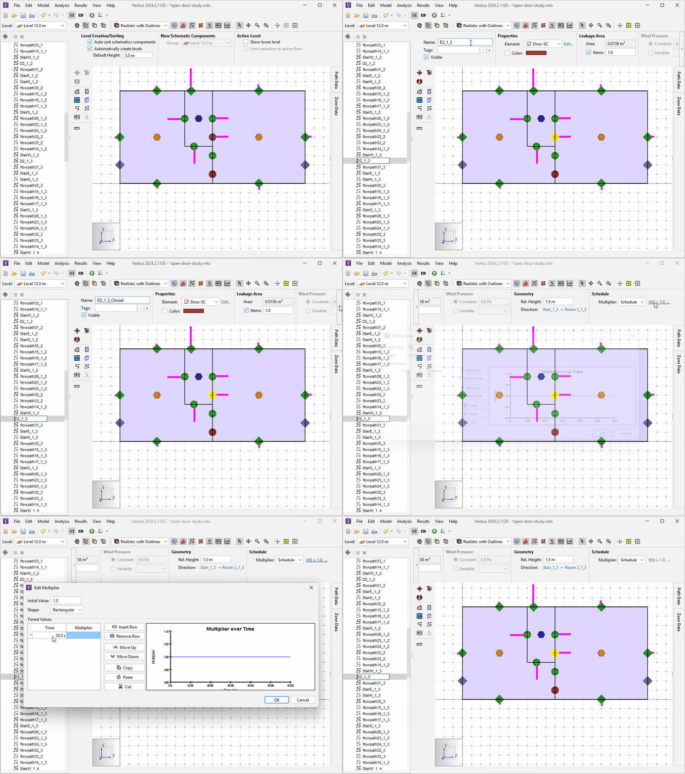
D2_1_3_Closed Flow PathWe have now modeled the closed state of our door.
For more information on how this Multiplier Schedule models the door state, see the Modeling Door States tutorial.
The final step is to model the open state of the door.
To do this, repeat steps 3-6 above, modifying the D2_1_3_Open Flow Path using the information in the table below.
D2_1_3_Open Flow Path| D2_1_3_Open | |
|---|---|
| Initial State | |
| 0.0 | |
| Mutiplier Schedule | |
| Time (s) | Multiplier |
| 30.0 | 1.0 |
| 300.0 | 0.0 |
Our model is now configured to model our open door scenario. The last step before we can run our model is to set up our Simulation Parameters to run our simulation in Transient mode.
Editing Simulation Parameters to run in Transient mode
To configure our simulation settings to run in Transient mode:
- Use the Analysis › Simulation Parameters action to open the Simulation Parameters dialog.
- In the Time tab, select the
Transientoption in the Airflow Simulation Method dropdown. - In the Simulator tab, check the box next to Vary density during time step.
- Click OK to apply the changes.
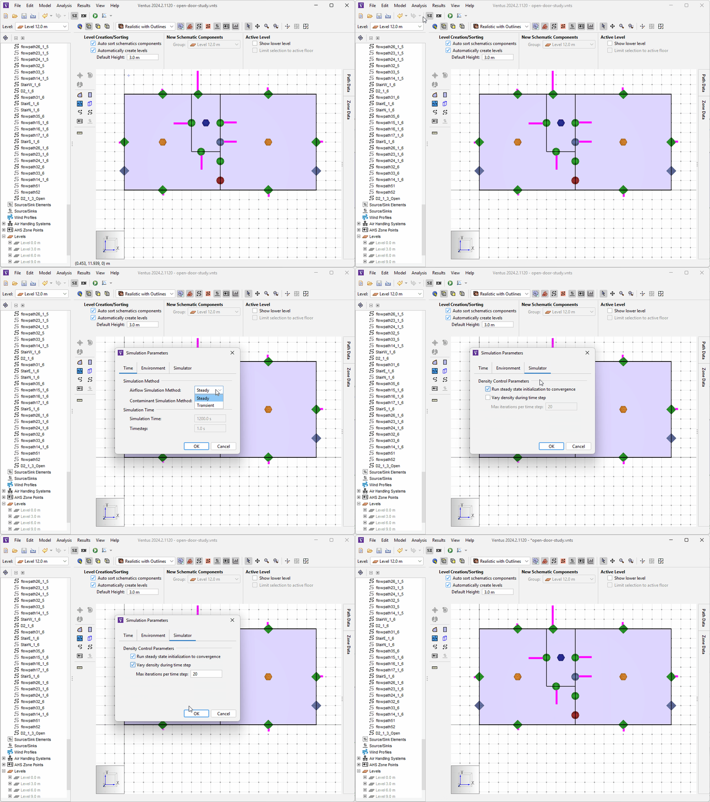
We are now ready to run the simulation.
Running the Simulation
To run the study:
- Click the Run icon
 .
The simulation should take only a few seconds.
 - When the simulation is complete, click OK in the Run Simulation dialog.
Analyzing Results
Unlike the Closed Door study, this is a Transient simulation, meaning that the differential pressures and flows of our Flow Paths change over time. To analyze the results of our simulation, we will need to use the Results Timeline. To begin our analysis:
- Click Path Data to open the Path Data Panel.
- Enter
D2in the Filter field to filter down to our stairwell door Flow Paths. - Enter
30sin the Results Timeline timestep field to begin our analysis to when our door should open. - Click the
 icon to begin playback of our results.
 - Pause playback at
35swhen, according to our standards, our flow needs to have stabilized at \(>1 \frac{m}{s}\).
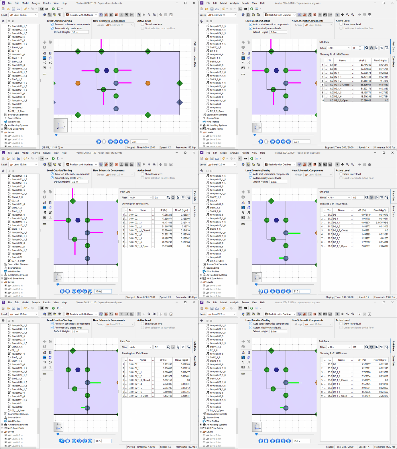
30s to 35sAs can be seen in Figure 6, the 3D flow vectors and the Path Data table update in real time based on the results data.
Prior to 30s, all of the flow at our event door is moving through D2_1_3_Closed.
After 30s, the flow switched to D2_1_3_Open.
Let us now examine the results at 35s.
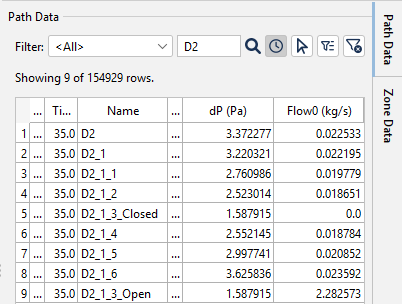
35.0sAs can be seen in Figure 7, the differential pressures of our closed shaft doors drop well below our design criteria because we opened the doors and windows on the fire event level.
However, the flow across the open door boundary, shown by the Flow0 column for the D2_1_3_Open Flow Path, increases significantly.
To convert this Mass Flow value to a velocity at the boundary, we will assume the standard density of air at sea level to be \(1.225 \frac{kg}{m^3}\) and use the following equation:
\(\frac{flow \frac{kg}{s}}{1.225 \frac{kg}{m^3} * 1.85 m^2} = velocity \frac{m}{s}\)
Plugging in our flow value:
\(\frac{2.282573 \frac{kg}{s}}{1.225 \frac{kg}{m^3} * 1.85 m^2} = 1.007 \frac{m}{s}\)
As can be seen, this flow velocity meets our design criteria requirement of \(1 \frac{m}{s}\).
We can also analyze our Flow Path data using the 2D plotting utility available in Ventus. To do this:
- Click the dropdown next to the
 icon and select Plot Primary Flows.
 - Deselect any selected Flow Paths.
- In the filter field, enter D2 to find our Flow Paths.
- Select the
D2_1_3_ClosedandD2_1_3_OpenFlow Paths to plot the flows for the Flow Paths.
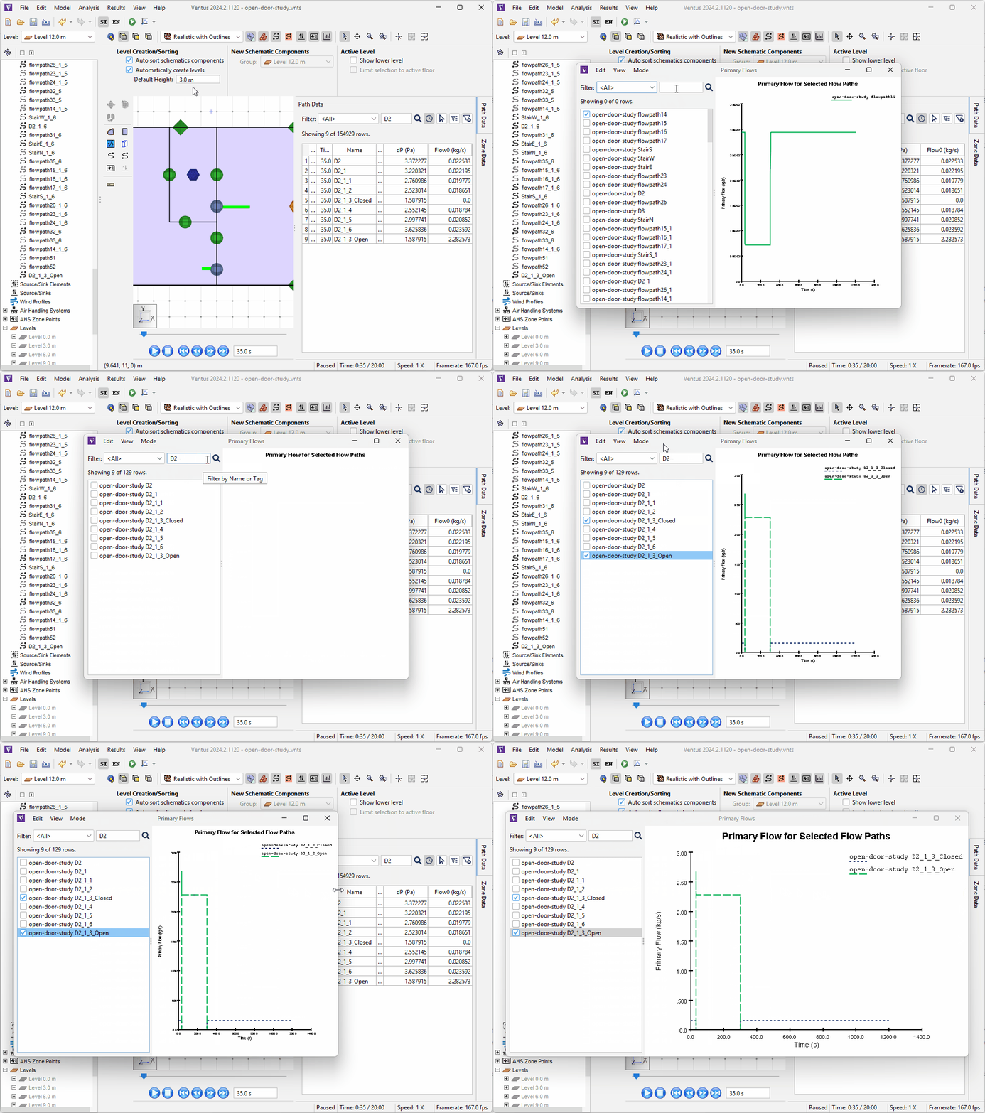
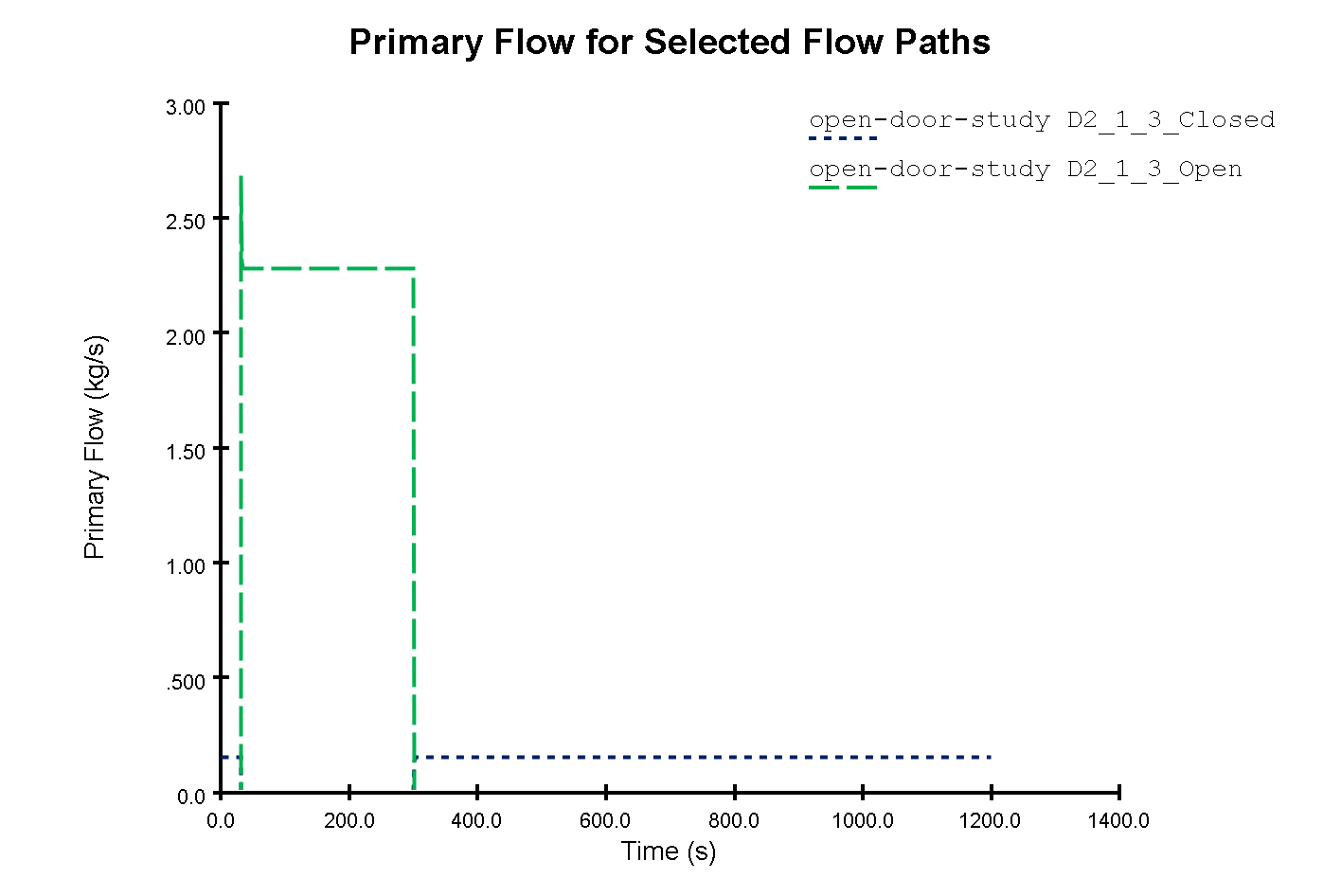
As can be seen from Figure 9, The flow through D2_1_3_Open increases at 30s and quickly levels off, before dropping again at 300s.
Inversely, the flow through D2_1_3_Closed decreases at 30s and stops completely, before increasing again at 300s.
Based on the transient results, we can see that our 4750 scfm fan design satisfies our \(1 \frac{m}{s}\) flow requirement within 5s of the door being opened.
Conclusion
You should now be familiar with how to model the open door scenario of a stairwell pressurization study.
To download the most recent version of Ventus, please visit the Ventus download page. Please contact support@thunderheadeng.com with any questions or feedback regarding our products or documentation.
Related Tutorials
This tutorial teaches the user how to perform a closed door Stairwell Pressurization study in Ventus.
This Feature Demo details the steps to model basic Contaminants in Ventus.
This Feature Demo details the steps to create a Ventus model with imported 3D geometry.
Tutorial demonstrating how to model a fire in Pyrosim.
(Legacy) Tutorial to experience the fundamental features of PyroSim
Tutorial demonstrating how to model a pressure relief vent in Pyrosim.
Update to a Pathfinder subway station passenger movement, using queues and triggers to simulate standard circulation, then an emergency evacuation.
Tutorial demonstrating how to model passenger movement in a large subway station.
