Overview
This is the first tutorial in our Stairwell Pressurization series intended for Fire Protection Engineers who wish to perform Stairwell Pressurization analysis with Ventus as part of their Smoke Control projects. It will demonstrate how to model and evaluate a simple fan-based Stairwell Pressurization system to determine if it complies with a given set of criteria. You will learn how to draw zones, create flow elements and flow paths, run the simulation, and evaluate the differential pressures and flows in a stairwell using the tools available in Ventus.
This tutorial will demonstrate the simplest Closed Door scenario of this type of analysis, with future tutorials covering more complex scenarios.
Before Starting
Before beginning this tutorial:
- Read through the Ventus Basic First Model tutorial to understand the basics of making a model in Ventus.
- Download and extract the Stairwell Pressurization - Closed Doors models to follow along.
Introduction
Most codes and standards regarding Smoke Control systems will provide criteria for stairwell pressurization systems that Fire Protection Engineers must comply with. Typically, these criteria involve a combination of:
- Minimum / Maximum Differential Pressures at Doorways
- Maximum allowable applied force at Doorways
- Minimum Flow Rates when a Stairwell door is open on a Fire Event Level
- Maximum times when Minimum Flow Rates must be achieved after a door is opened on a Fire Event Level
In this tutorial series, we will model and evaluate a building with a similar set of criteria. These criteria are not taken from a specific standard, however they are similar to real standards. When designing your own systems, you should select an appropriate standard for your own use. The criteria we will use are as follows:
| Design Criteria | |
|---|---|
| Stairwell Doors Closed | |
| Differential Pressure at Doorways | 25-50 Pa |
| Maximum Applied Force at Doorways | 100 N |
| Stairwell Door Open at Fire Event Floor | |
| Minimum Flow Rate at Open Doorway | 1 m/s |
| Maximum time to achieve flow | 5 s |
Geometry Overview
This tutorial will use the geometry from the Ventus Basic First Model tutorial. This geometry features a simple 3 zone floorplan, with two rooms and one stairwell.
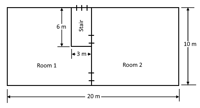
The model we are using specifically is the Summer variant of the model modeled in that tutorial. If you would like to see how this model is created, you can follow along in the Basic First Model tutorial.
This model as it exists now does not include any forced pressurization system. We will add a fan to the stairwell and size it such that it meets the criteria laid out in Table 1.
The model is also currently in the closed door configuration. We will modify it later to perform the open door analysis. The doors in this model are assumed to have a Cross-sectional area of \(1.85m^2\).
The Closed Door Study
Defining Fans
Fans in Ventus are currently modeled with AHS Zone Points. An AHS Zone Point connects a Zone to a Simple Air Handling System. AHS Zone Points act to add (Supply) or remove (Return) gases from Zones.
In this case, we wish to model the addition of gas (air) to a Zone via a fan, so we will use a Supply AHS Zone Point.
To add the Supply point to the model:
- Open the
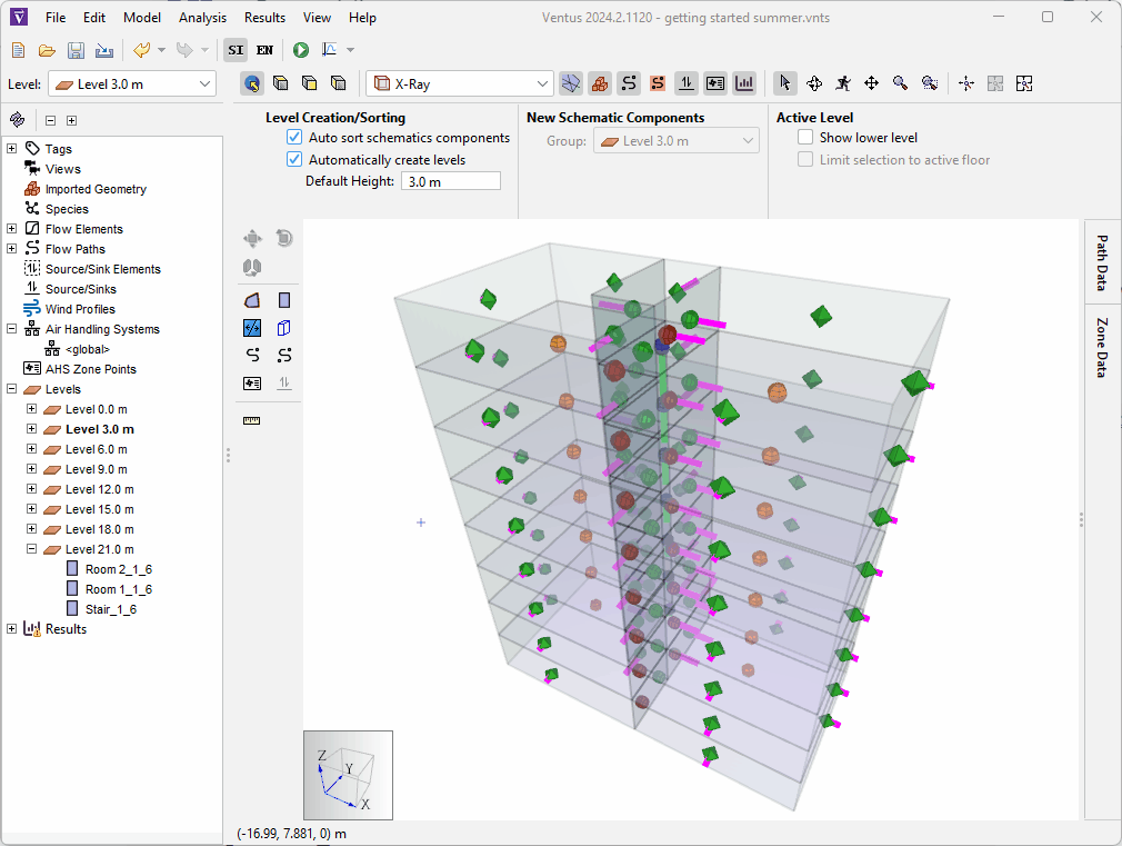
getting started summer.vntsmodel that you downloaded above. - Right-click on Level 21.0 m in the navigation tree and click Set as Active Level
- Click the
 icon to switch to the Top View.
 - Click the AHS Zone Point tool
 .
. - In the Property Ribbon, give the Zone Point the name
fan. - Also in the ribbon, ensure that the Types field is set to
Supply, then set the Design Flow Rate field to1000 scfm. - Place the AHS Zone Point by moving the tool over the central zone in the model,
Stair_1_6, and left-clicking.
We are now ready to run and analyze the closed door Study.
Running the Simulation
To run the study:
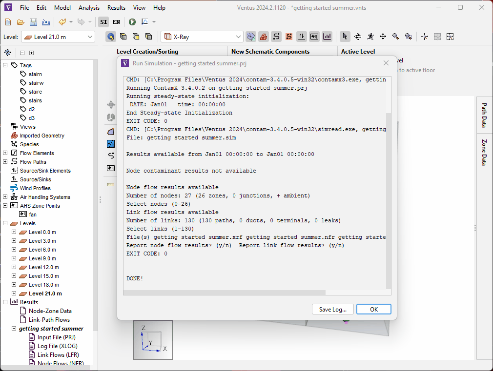
- Click the Run icon
 .
The simulation should take only a few seconds.
.
The simulation should take only a few seconds. - When the simulation is complete, click OK in the Run Simulation dialog.
Analyzing Results
To analyze the data for our simulated Stairwell, we need to analyze the relevant Flow Paths for doors in that shaft.
In our case, this is the D2 Flow Path, and all of its copies on higher floors.
To view the results for these Flow Paths:
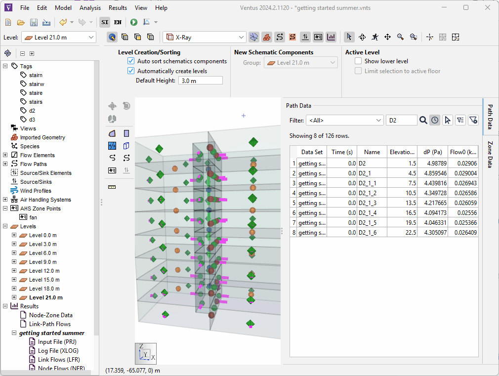
- Click the Path Data button in the Ventus UI to show the Path Data panel.
- In the filter box at the top of the panel, type in
D2. This will filter the data to only show Flow Paths withD2in their name. Note that this filter field is case sensitive.
The dP column of this table shows the differential pressures across the Flow Path.
As can be seen from this data, a 1000 scfm fan only provides a ~4 Pa pressure across the closed door Flow Paths in our stairwell.
This is not sufficient to meet the requirements from Table 1.
Adjusting Fan Size
We will adjust the fan size and run the simulation again to meet our design criteria. To do this:
- Click the
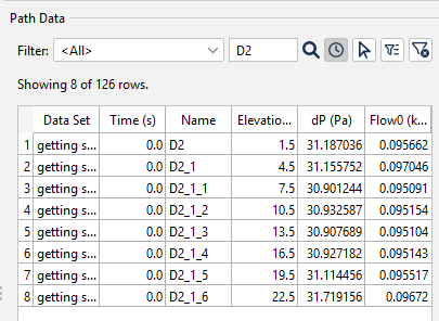
fanAHS Zone Point in the navigation tree. - Change the Design Flow Rate field to
3500 scfm. - Click the Run icon again to re-run the simulation.
Note that the Path Data table automatically updates based on the new simulation data.
From this new results data, we can see that the fan size of 3500 scfm results in closed door pressures of ~30 Pa.
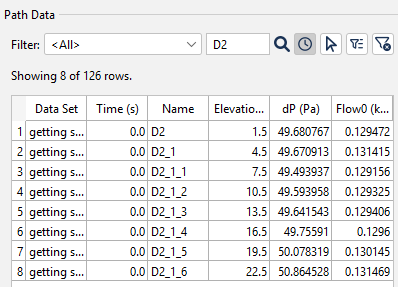
3500 scfm fan- Repeat the steps above to change the fan size to
4750 scfm.
You can see that the fan size of 4750 scfm results in closed door pressures of ~50 Pa.
4750 scfm fanWith this information we now know that to satisfy our design criteria, we need a single pressurization fan that can provide 3500 scfm - 4750 scfm.
We can convert this maximum allowable pressure (50 Pa) and the assumed size of our door (\(1.85 m^2\)) in to applied force to evaluate our compliance with that criteria as well.
Using these to values, we evaluate:
\(50 \frac{N}{m^2} * 1.85 m^2 = 92.5 N\)
We know that the maximum force applied to any of our closed doors is 92.5 N, which falls within our design requirements.
If we had doors with a larger area in this stairwell, we might have needed to reduce our maximum pressure within the allowable range of 30 - 50 Pa to avoid exceeding our force requirement.
Results
In summary, our analysis thus far has yielded the following design requirements for our system:
| Scenario | Fan Size (scfm) |
|---|---|
| Doors Closed | 3500 - 4750 |
If we only need to design for the Closed Door scenario, we would need a fan that falls in the 3500 scfm - 4750 scfm range.
We will continue to add to this table in future tutorials to determine our final system sizes.
Conclusion
You should now be familiar with how to use Ventus to perform a Closed Door Stairwell Pressurization study. Ventus accelerates this type of study by providing tools that makes processes of modeling and analysis much faster. Continue the tutorial series by clicking the link to the Open Door Studies tutorial below.
To download the most recent version of Ventus, please visit the Ventus Download page. Please contact support@thunderheadeng.com with any questions or feedback regarding our products or documentation.
Recommended Tutorials
This tutorial teaches the user how to perform an open door Stairwell Pressurization study in Ventus.
This Feature Demo details the steps to model door state changes in Ventus
Related Tutorials
This tutorial teaches the user how to perform an open door Stairwell Pressurization study in Ventus.
This Feature Demo details the steps to model basic Contaminants in Ventus.
This Feature Demo details the steps to create a Ventus model with imported 3D geometry.
Tutorial demonstrating how to model a fire in Pyrosim.
(Legacy) Tutorial to experience the fundamental features of PyroSim
Tutorial demonstrating how to model a pressure relief vent in Pyrosim.
Update to a Pathfinder subway station passenger movement, using queues and triggers to simulate standard circulation, then an emergency evacuation.
Tutorial demonstrating how to model passenger movement in a large subway station.