Overview
This tutorial is intended for users of Ventus that wish to model a state change of a door during a transient simulation. It will demonstrate how to model this phenomenon using a combination of Flow Paths and Multiplier Schedules. You will learn how to define the necessary Flow Elements, create the Flow Paths, and configure the Multiplier Schedules to control the state of your model.
Before Starting
Before beginning this tutorial:
- Download the Modeling Doors models to follow along.
- Read through the Schedules section in the User Manual.
- Read through the Flow Elements section in the User Manual.
- Read through the Flow Elements section in the User Manual.
Introduction
When modeling building spaces in Ventus, it is often desired to evaluate what happens when a door or other orifice opens in the model. This would increase the amount of flow that can pass through the orifice, which could significantly affect the results of the simulation. This tutorial will show you how this phenomenon can be modeled in Ventus.
To showcase this ability, we will use a simple two Zone model.
This model is available in the modeling-doors-start.vnts model that you downloaded in the zip archive above.
This model is a simple two-Zone compartment model.
Each Zone in the model has a pre-modeled wall leakage Flow Path on one of its exterior walls, and the left Zone additionally has a 1000 scfm AHS Supply to pressurize the model.
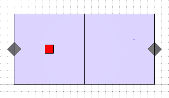
This model is also configured to use the Transient Simulation method to analyze non-steady state flow effects in the model.
The default run time for this is 1200s.
We will modify this model to add 3 new Flow Paths - 2 of these will represent open doors, and the other 1 will model the closed state of one of the doors. One of the doors is an exterior door that will always be in the open state.
Defining the Flow Elements
To model the change in door states, we first need to define the Flow Elements that will represent each of the states. To do this:
- Open the
modeling-doors-start.vntsmodel downloaded above. - Use the Model › Edit Flow Elements action to open the Edit Flow Elements dialog.
- Click New to open the New Flow Element dialog.
- Enter the name
Door Leakageand select theLeakage Areamodel. - Click OK to create the new Flow Element.
- In the Edit Flow Elements dialog for the
Door Leakageelement, select the Per Item option in the Type dropdown. - Enter \(0.0158 m^2\) in to the Area per Item field.
- Click Apply to save the changes.
- Click New to open the *New Flow Element dialog.
- Enter the name
Door Openand select theOrifice Areamodel. - Click OK to create the new Flow Element.
- In the Edit Flow Elements dialog for the
Door Openelement, enter \(1.85m^2\) in the Cross-Sectional Area field. - Click OK to apply the changes.
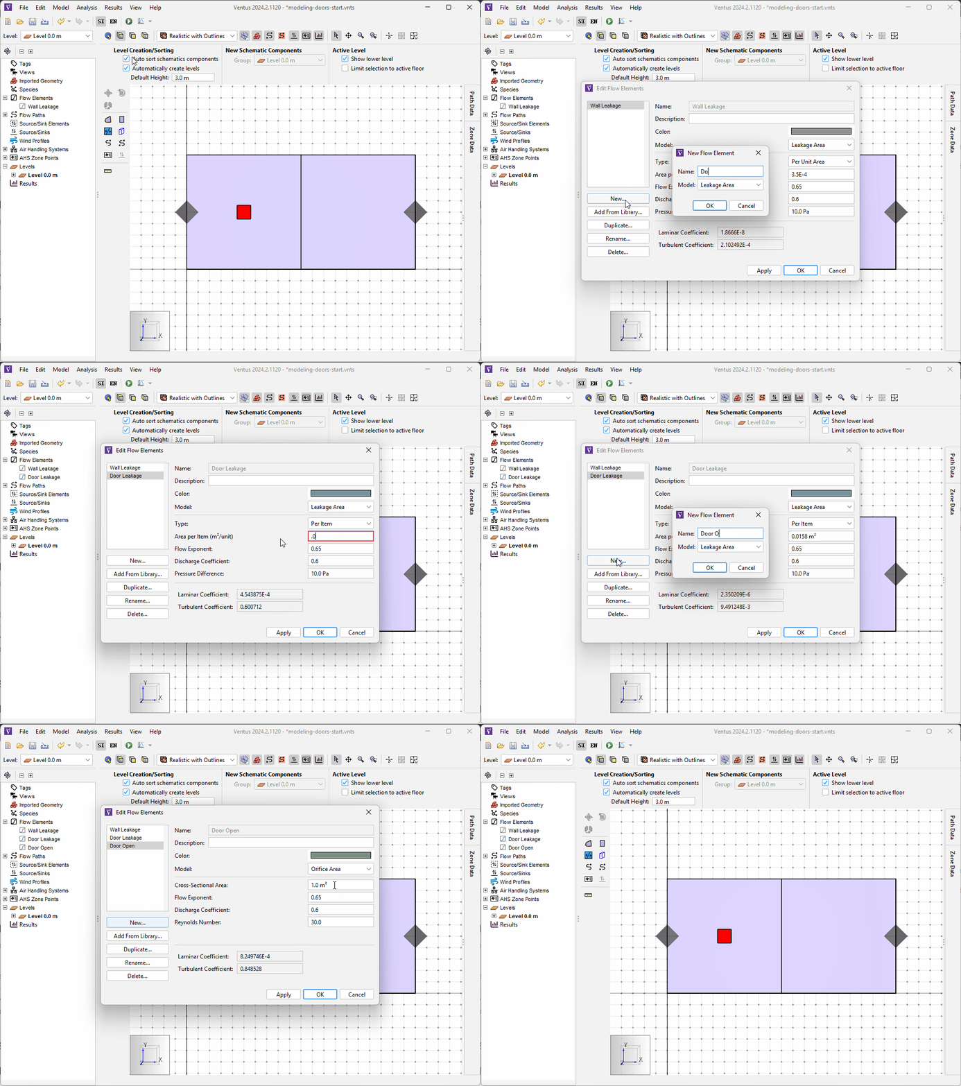
The Flow Elements are now ready for use in our Flow Paths.
Creating the Flow Paths
As discussed above, we will create 3 Flow Paths in the model.
2 of them will use the Door Open Flow Element, and the other will use the Door Leakage Flow Element.
To create these Flow Paths:
- Click the
 icon to switch to the Top View.
 - Double-click the
 icon to select the Two Point Flow Path tool in pinned mode.
 - In the Tool Properties ribbon, select the
Door OpenFlow Element in the Element field. - Draw a line across the wall between the two Zones to create a Flow Path modeling the open state of a door between the two compartments.
- Draw an additional line on the exterior wall of the right Zone to create a Flow Path modeling an open exterior door.
- In the Tool Properties ribbon, select the
Door LeakageFlow Element in the Element field. - Draw a line across the wall between the two Zones to create a Flow Path modeling the closed state of a door between the two compartments.
- Rename the Flow Paths
Door Open,Exterior Door Open, andDoor Leakage, respectively.
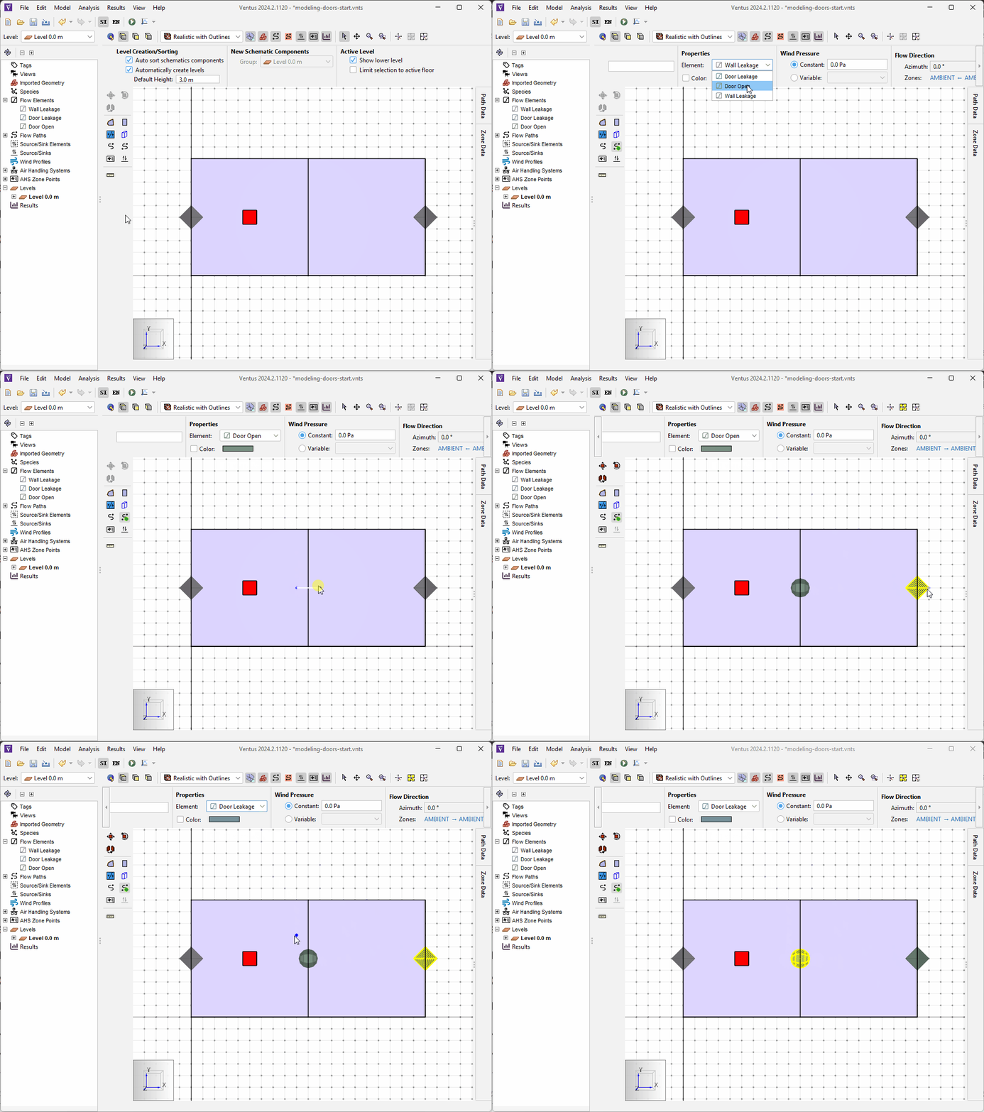
The Flow Paths are now created.
Defining the Multiplier Schedules
Multipliers on Flow Paths control what perecentage of modeled flow is allowed to flow through the Flow Path.
This is specified with a range of 0.0 (No Flow) to 1.0 (Full Flow).
This can be used to model a "Closed" state, the prevents any flow, and an "Open" state, that allows the full value of flow.
In complex cases, it can even be used to model transient states that allow partial flow.
It is possible to define Multipliers with Schedules. A Schedule as applied to Multipliers is a table of Times and Multiplier values. At any time listed in the table, the Multiplier value is changed to the value provided in the table. This allows us to effectively model different logical states of Flow Paths in our models.
We will use Multiplier Schedules in this example to model the Open / Closed state of our Door Open and Door Leakage Flow Paths.
The Door Open Flow Path will have a multiplier value of 1.0 when the door is supposed to be open, and the Door Leakage will have a value of 0.0 at the same time.
Inversely when the door is closed, the Door Open will have a value of 0.0 and Door Leakage will have a value of 1.0.
In this case, the Door Leakage Flow Path models the slight leakage of air around the door in the closed door state.
We will model our door to open at 30s and close again at 1170s.
The Multiplier Schedules to model this state change are listed in the tables below.
Door Open Flow Path| Door Open | |
|---|---|
| Initial State | |
| 0.0 | |
| Mutiplier Schedule | |
| Time (s) | Multiplier |
| 30.0 | 1.0 |
| 1170.0 | 1.0 |
| 1170.1 | 0.0 |
| 1200.0 | 0.0 |
Door Leakage Flow Path| Door Open | |
|---|---|
| Initial State | |
| 1.0 | |
| Mutiplier Schedule | |
| Time (s) | Multiplier |
| 30.0 | 0.0 |
| 1170.0 | 0.0 |
| 1170.1 | 1.0 |
| 1200.0 | 1.0 |
These settings model a door that initially starts closed To configure the Multiplier Schedules:
- Select the
Door OpenFlow Path. - In the Properties Ribbon, set the Multiplier dropdown to Schedule.
- Click the hyperlink next to the Multiplier dropdown to open the Edit Multiplier dialog.
- Enter
0.0in to the Initial Value field. - Enter the data points from Table 1 in to the Timed Values table.
- Click OK to apply the changes.
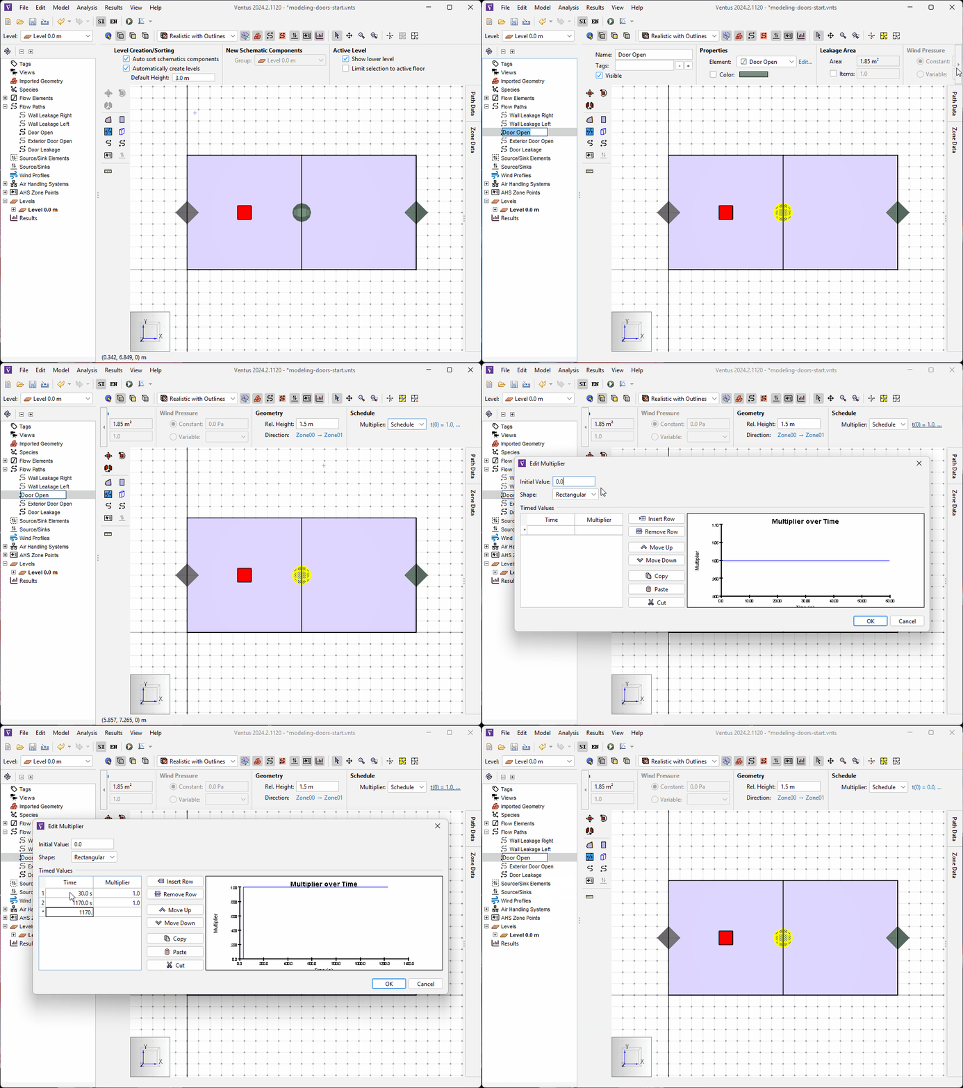
Door Open Flow Path.- Repeat Steps 1-6 above for the
Door LeakageFlow Path, using the data in Table 2.
The Multiplier Schedules are now configured.
Running the Simulation
We are now ready to run the simulation. To do this:
- Click the Run icon
 .
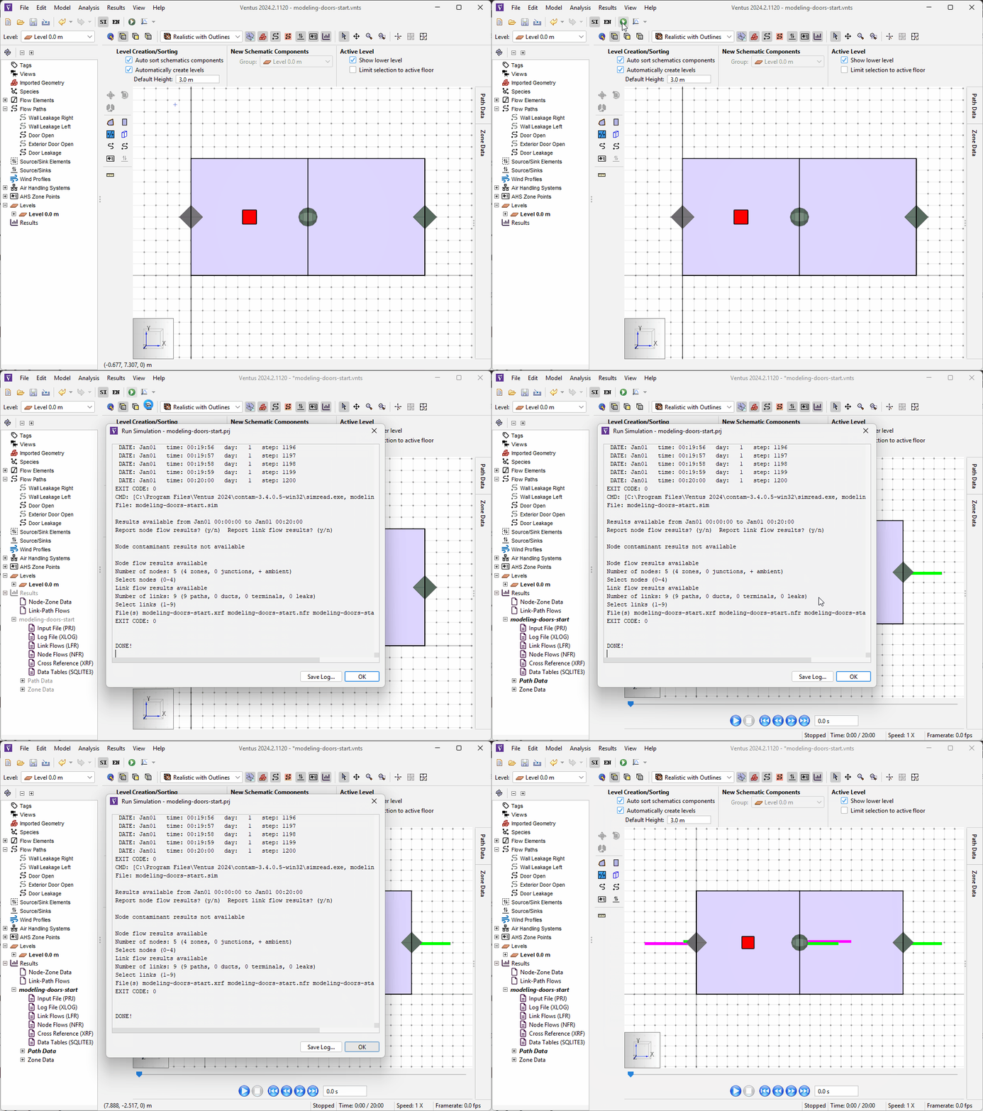
The simulation should take only a few seconds.
 - When the simulation is complete, click OK in the Run Simulation dialog.
The simulation should complete in a matter of seconds, and you should see the 3D Flow Path visualizations update in real time, showing the flow vectors at each Flow Path.
Results
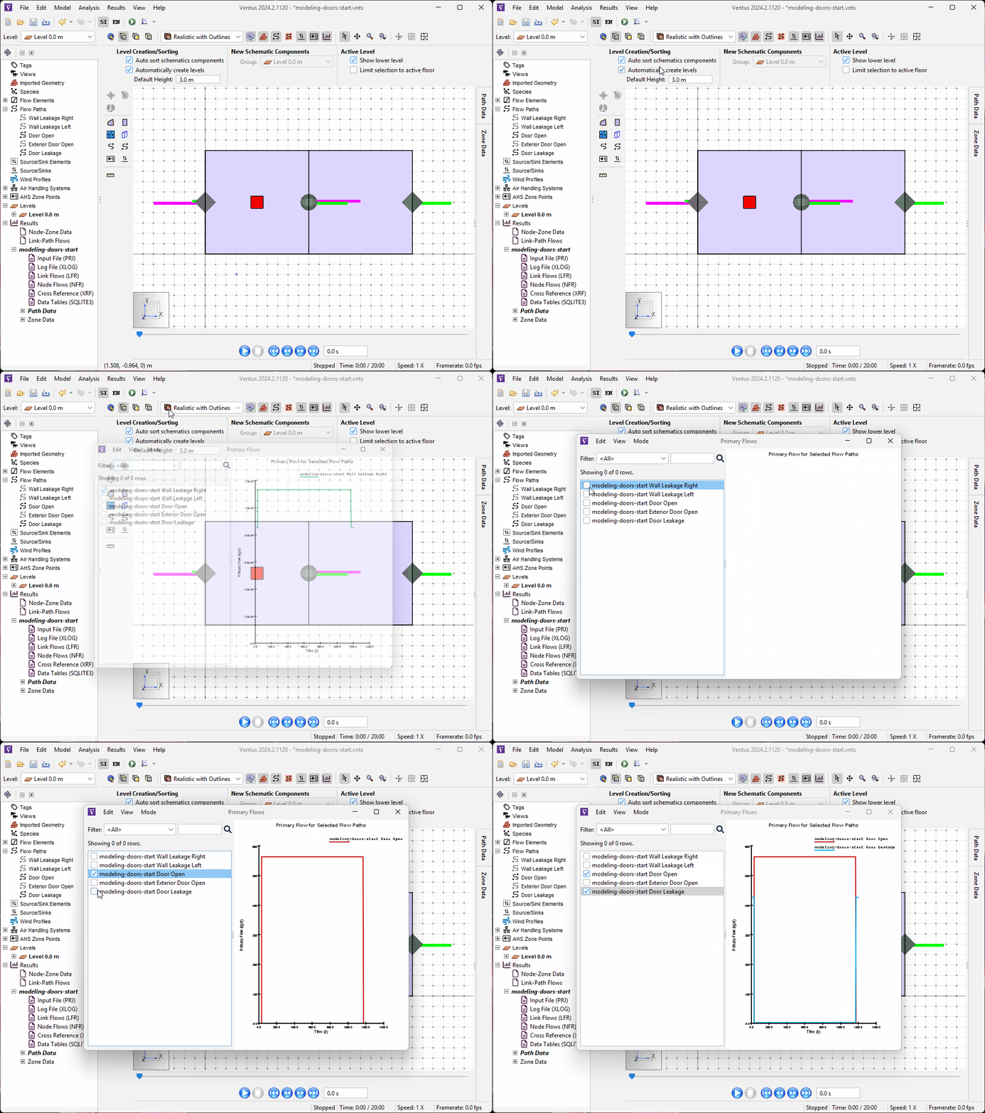
We will now examine the Flows through the 2 Flow Paths that model our door. To do this:
- Click the dropdown next to the
 icon.
icon. - Click Plot Primary Flows to open the Primary Flows dialog.
- Select the Door Open and Door Leakage Flow Paths and deselect any other flow paths in the selection tree on the left.
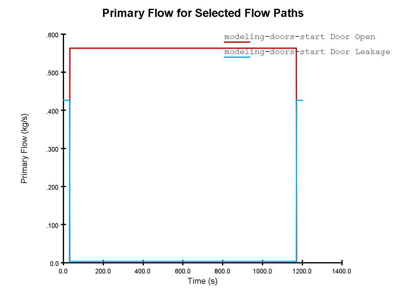
As can be seen from the plot above, our Door Open Flow Path activates at 30s and deactivates at 1170s.
During this time period, this Flow Path allows an increased amount of flow compared to the maximum value of the Door Leakage Flow Path.
We can also see that during the same time period, the Door Leakage Flow Path deactivates, preventing the doubling of flow through this region.
Conclusion
You should now be familiar with how to model door states in Ventus. Use this technique in your own models to increase the fidelity of your simulations.
To download the most recent version of Ventus, please visit the Ventus download page. Please contact support@thunderheadeng.com with any questions or feedback regarding our products or documentation.
Related Tutorials
This Feature Demo covers how to use the Performance Curve Flow Element
This Feature Demo details the steps to model basic Contaminants in Ventus.
Learn when and how to model Two-way Flow in Ventus.
(Legacy) Tutorial to experience the fundamental features of PyroSim
Video tutorial demonstrating the variables that may have an effect on evacuation time from aircraft cabins.
To demonstrate basic Ventus capabilities, we model a simple multi-story building for winter and summer conditions.
Tutorial demonstrating how to model jet fans in Pyrosim.
Tutorial demonstrating how to model a pressure relief vent in Pyrosim.
