 |  |
To follow along with this post, download the zip folder: Import 3D zip.
Introduction
In this tutorial, we demonstrate creating a Ventus model by importing 3D CAD models. Ventus can import many types of CAD models, including: ifc, ifcxml, dxf, dwg, and fbx file formats. We demonstrate import of a dwg model, but the approach is similar for all CAD formats.
Ventus has capabilities to accelerate this process: level clipping, Flow Path visualization settings, and imported geometry settings. We demonstrate these capabilities within the context of air flow analysis for a multi-story office building.
Background - Working with Levels
Levels are the basic building blocks of a Ventus model; the Z-coordinate of each zone is defined by absolute height above a model origin. Each object (ie. Flow Paths, AHS Supplies, and Sources) is defined by its relative height above the associated level.
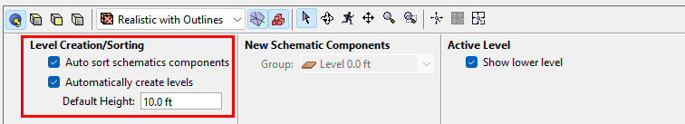
In the Property panel, the Default Height defines the default distance between levels.
In the following examples we will frequently say: at the top of the Navigation panel, in the Level list dropdown, select Add New.
When this is done, the default behavior is to:
- Add a new level above highest existing level.
- The Working Z of the new level will be determined by the highest existing level plus the Default Height in Figure 2.
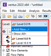
In this case, the highest existing level has a Working Z of 10 ft and with a Default Height of 10 ft, the new level will be created: Level 20.0 ft.
Once a level is created, there are several additional controls that are displayed when a level is selected.
- Zone Geometry
- The Working Z is the plane from which new zones will be drawn (the floor height for zones on this level). This is also the default name for each zone, and it cannot be changed once a level is created.
- The Level Height is the zone height from floor to ceiling, used when calculating wall Flow Path areas and zone volumes. This height is measured relative to the level Working Z.
- Object View Associations
- Z Min Filter is used for display purposes.
Any geometry that is below the Z Min Filter will not be displayed as part of that level.
Usually this is left at the default
CURR_LEVELvalue, identical to the Working Z. - Z Max Filter is used for display purposes.
Any geometry that is above the Z Max Filter will not be displayed as part of that level.
Usually this is left at the default
NEXT_LEVELvalue, identical to the next level Working Z.
- Z Min Filter is used for display purposes.
Any geometry that is below the Z Min Filter will not be displayed as part of that level.
Usually this is left at the default
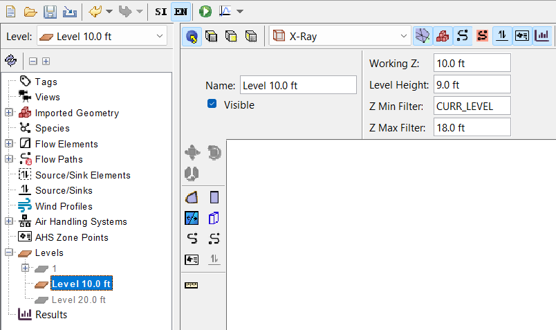
As displayed in Figure 4, there is a level named Level 10.0 ft with some additional controls:
- Zones that are drawn with this level as the active level will have floors starting from an X-Y plane at a height of 10 ft.
- Due to the Level Height, zones on this level will have 9 ft high walls; the wall leakage areas will use that height when calculating leakage area. Zone volumes, required for transient modeling, will also use the Level Height value in the volume calculation.
- The geometry that is below the
CURR_LEVELWorking Z will be clipped. This will hide objects (ie, Flow Paths and imported geometry) below 10 ft when this level is the active level. - The top of this level is clipped at 18 ft in the model, which will hide objects above 18 ft by default when this level is the active level.
Example Model
Open a new Ventus model. In the Main toolbar, select EN for English (US Customary) units.
Import the DWG File
Use the Pathfinder-Fundamentals.dwg file from the zip folder.
To import the CAD file:
- In the File menu, click Import. Select the file Pathfinder-Fundamentals.dwg.
- In the Import dialog:
- In Import Location select Into the current model and click Next.
- In Units select mm and click Next.
- In Import Settings leave default values and click Next.
- Click Finish.
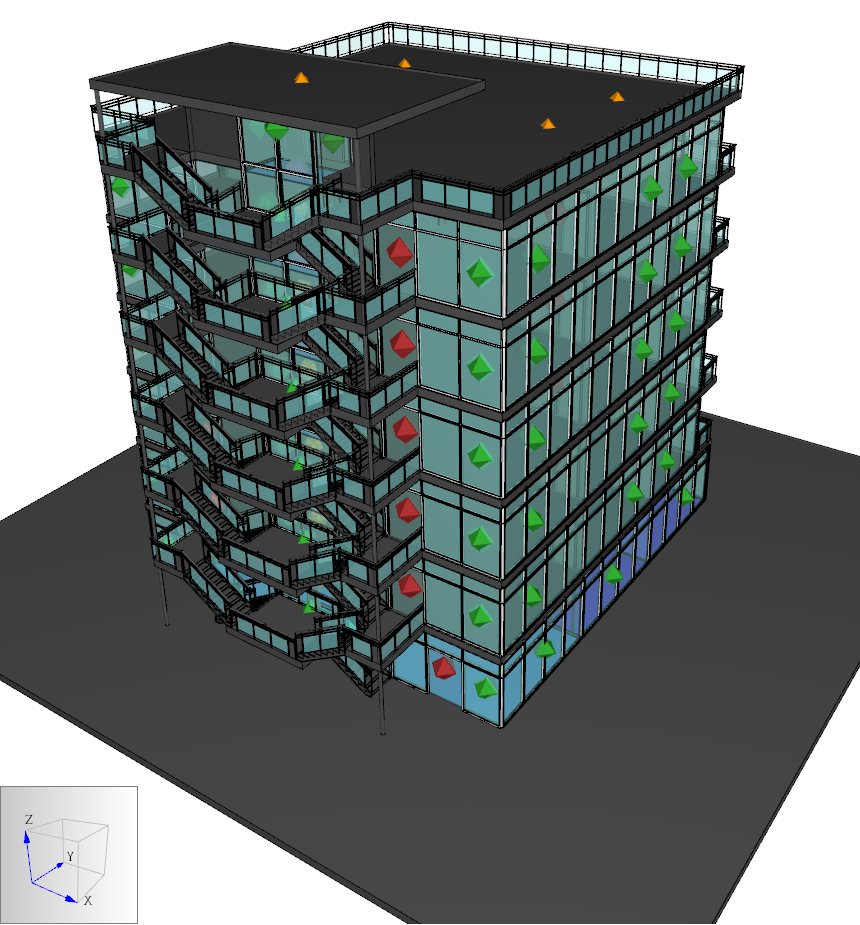
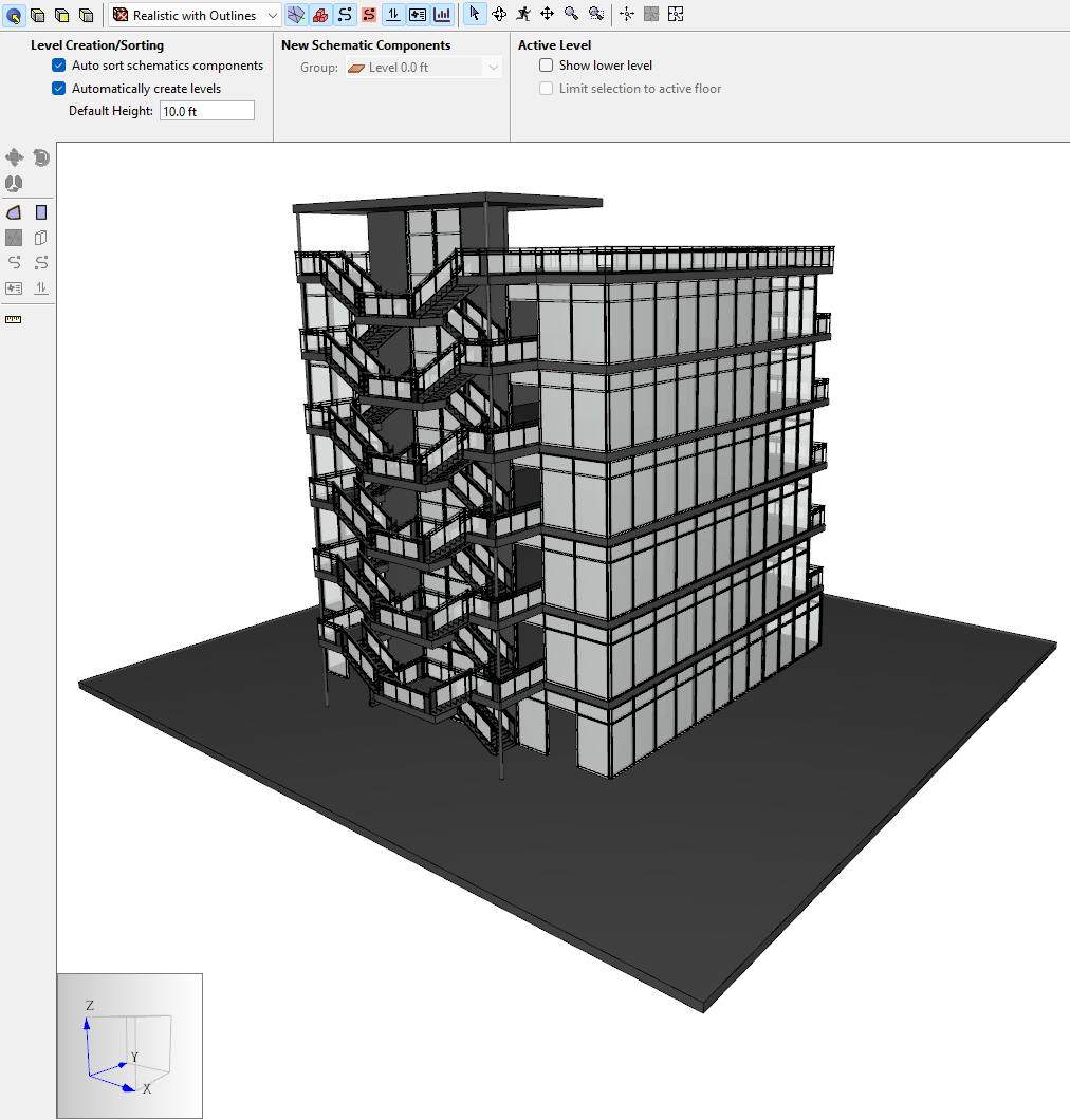
- In the View toolbar, change the geometry render setting to Realistic with Outlines. The model should resemble Figure 5.
Save the Ventus model:
- In the File menu, click Save and save the Ventus as import_3d.vnts.
Improve the Model Appearance
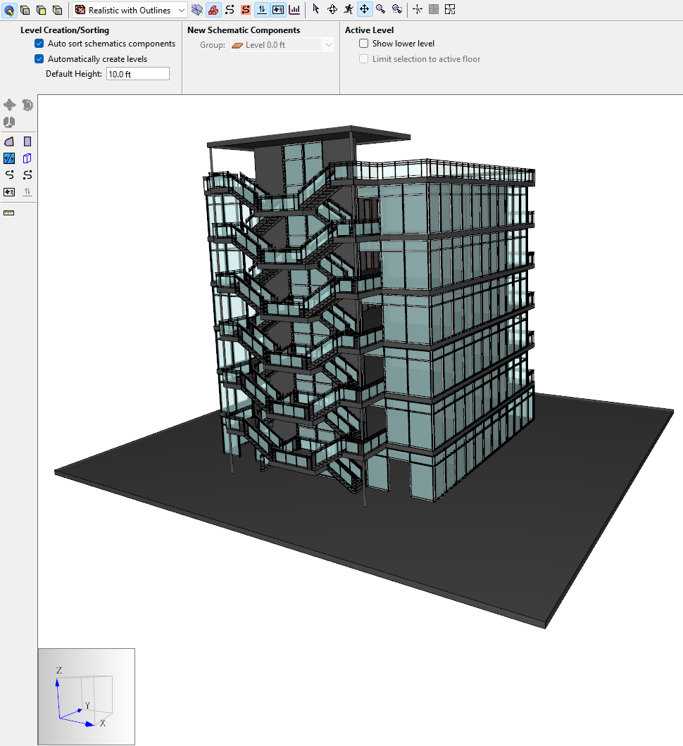
Change the display of the glass:
- Spin the model and click on a glass window.
- In the Property panel, click Material. The Materials menu will open.
- In the Materials menu, select Glass.
- Change the assigned color to a light blue and change the opacity to 20%.
- Click Advanced Materials.
- In the Advanced Materials dialog, change the Shininess Value to 75.
- Click OK to close the Advanced Materials dialog.
- Click OK to close the Material dialog.
- Save the model.
Inspect the Geometry Floor Heights
We want to set the correct Default Height and level locations for the model. To do this, we need to explore the imported geometry.
Change the viewing angle and identify Z bounds:
- Rotate the model so that you can click on the different floors. If needed, you can Hide windows or ceilings to allow access for selecting.
Click on the floor slab for the second level.
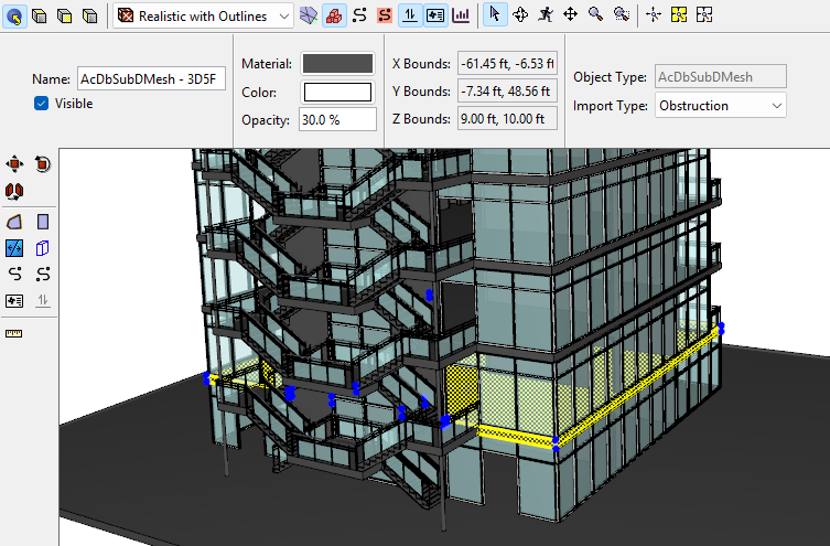
Figure 7. When the floor slab for the second level is selected, Z Bounds for the mesh appear in the Property panel. As shown in Figure 7, the Z bounds are 9 ft and 10 ft.
- If we click the floor slab for the third level, the Z bounds are 19 ft and 20 ft. This pattern continues until above the roof.
- If we click the highest concrete slab for the building, the Z bounds are 68 ft and 69 ft.
We have observed:
- The distance between levels is 10 ft
- The thickness of each floor slab is 1.0 ft
- The second level floor slab caps the walls of the first level off at 9 ft.
- The roof level floor has a wall height of 8 ft
Determine the First Level Bounds
Next:
- In the Object tree, select
Level 0.0 ft. In the Properties panel, change the Z max filter to 10 ft. The display should resemble Figure 8.
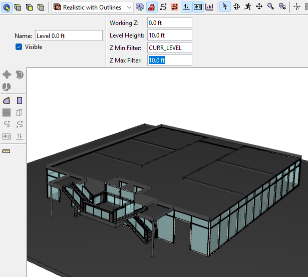
Figure 8. Clipping of the model when Z Max Filter 10 ft is applied The view of the imported geometry has been clipped; Ventus renders only the imported geometry associated with any level. Imported geometry above 10 ft is no longer associated with any level, so it becomes hidden.
Note that our view of the level geometry is obscured by the floor slab of the second level. To address this undesirable behavior we will further edit our clipping plane.
Change the Z max filter to 9 ft. The display should resemble Figure 9.
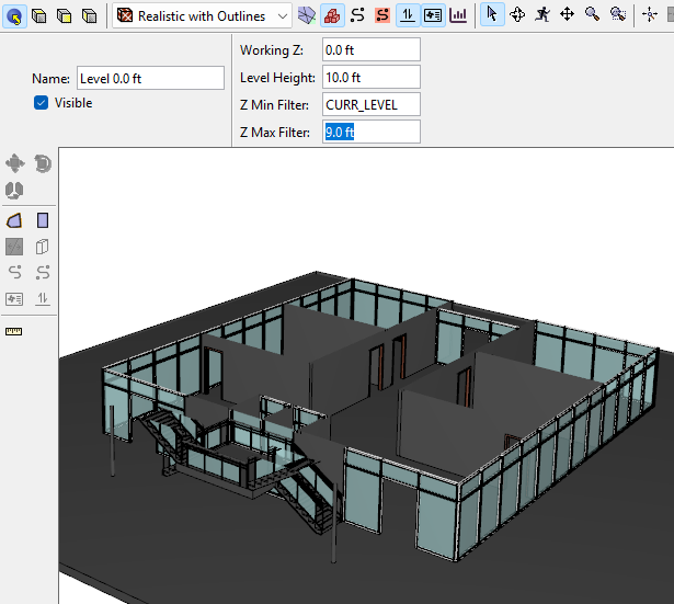
Figure 9. Clipping of the model when Z Max Filter 9 ft is applied (preferred) Again, Ventus renders only the geometry associated with the first level. This time, the bounds align with our desired representation. Like the first level, each level volume can include the floor slab that supports the occupied volume of building space.
We can model the levels to each include either the floor slab above or the floor slab beneath it. Due to the macroscopic focus of Ventus, we choose to include floor slabs within the entire air volume for each level.
- As an optional step, adjust our level bounds to include the floor slabs.
- With the first level,
Level 0.0 ftactive, change the Level Height to 9 ft. - Leave the Z Max Filter set to 9 ft as in Figure 9.
- When no object is selected, in the Property Panel Default Height should be set to 10.0 ft. All other levels will have a height of 10 ft.
- With the first level,
- Ensure that Ventus is set to Auto sort schematics components as part of Level Creation/Sorting; Automatically create levels should also be ON.
Determine the Model Level Locations
To add seven additional levels:
- At the top of the Navigation panel, in the Level list dropdown, select Add New.
- Change the new Level Location (working Z) to 9 ft.
- Click OK or press Enter.
- Add the third level, changing the new Level Location (working Z) to 19 ft.
- Repeat four more times until the new level is at 59.0 ft.
- Change the Level Height for
Level 59.0 ftto 9 ft. This allows for 8 ft of wall and 1 ft of floor. - Add the eighth level, changing the new Level Location (working Z) to 68 ft. The Level Height for this top level will not matter; leave it as 9 ft.
Level data should resemble Table 1.
| Count | Working Z | Level Height | Z Min Filter | Z Max Filter |
|---|---|---|---|---|
| 1 | 0.0 | 9 | CURR-LEVEL | 9 |
| 2 | 9.0 | 10 | CURR-LEVEL | NEXT_LEVEL |
| 3 | 19.0 | 10 | CURR-LEVEL | NEXT_LEVEL |
| 4 | 29.0 | 10 | CURR-LEVEL | NEXT_LEVEL |
| 5 | 39.0 | 10 | CURR-LEVEL | NEXT_LEVEL |
| 6 | 49.0 | 10 | CURR-LEVEL | NEXT_LEVEL |
| 7 | 59.0 | 9 | CURR-LEVEL | NEXT_LEVEL |
| 8 | 68.0 | N/A | CURR-LEVEL | NEXT_LEVEL |
Check your work
- When no object is selected, turn Show lower level OFF.
Select one of the middle levels as the active level. This will clip the display, showing only the objects and geometry associated with the level. As desired, the rendering has the floor slab and the geometry of this level only, as in Figure 10.
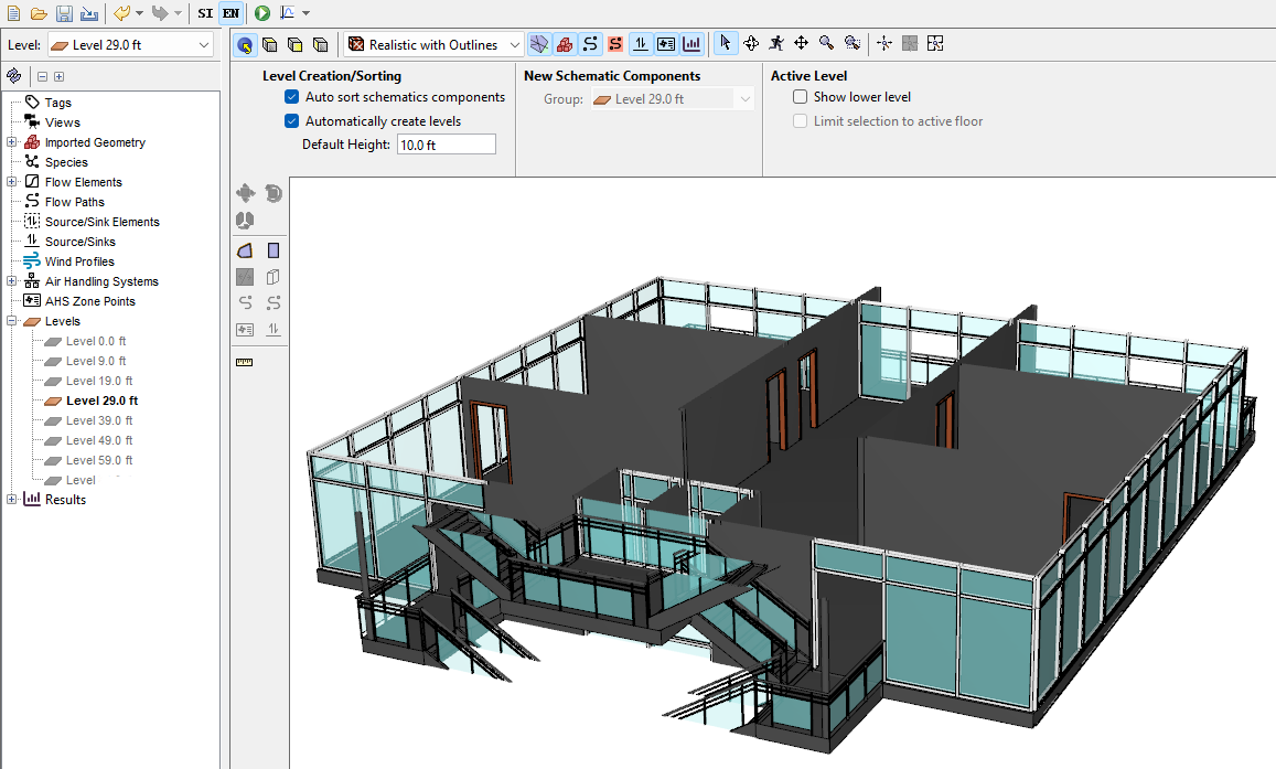
Figure 10. A middle level of the model is active: notice the screen clipping includes the floor slab at the bottom of this level. If we had clipped each level to include the floor slab above, it would be more difficult to see geometry from above.
- When no object is selected, turn Show lower level ON.
- Set the top level,
Level 68.0 ftas the active level. As desired, the view window has the roof concrete slab. Toggle Show lower level ON, as in Figure 11.
Figure 11. The top level is active; rendering of the seventh level toggles on and off. With this method, the screen clipping includes the concrete roofing slab as part of the upper roof, but not as part of the habitable roof.
Draw the Zones and Flow Paths for the first level
We can now draw the zones for the first level.
To draw zones and Flow Paths for the first level:
- In the Object tree, right-click
Level 0.0 ftand select Set as Active Floor. - In the View toolbar, select Top View and click
 Reset All.
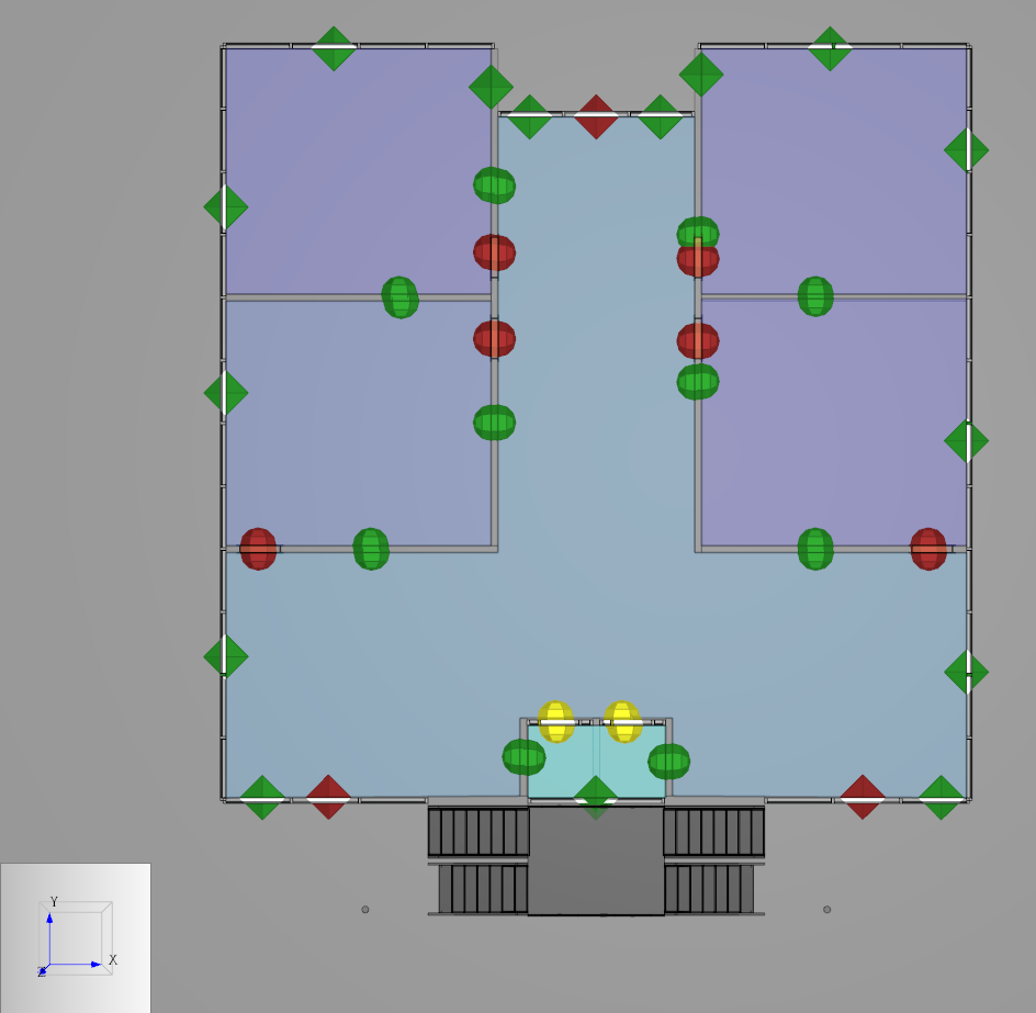
 - Draw zones using the Add a Rectangular Room and Add a Polygonal Room tools to model rooms. Notice that you can snap to the imported geometry when drawing. We assigned blue to the zones and defined an opacity of 50 %.
Add Flow Paths to account for wall leakages and leakage items such as doors.
Here, we use the default Ventus AREA/Area, AREA/Item and SHAFT Flow Elements for demonstration. We also use the DOOR-EL Flow Element from the Ventus Validation 3 Tutorial, represented in Table 2.
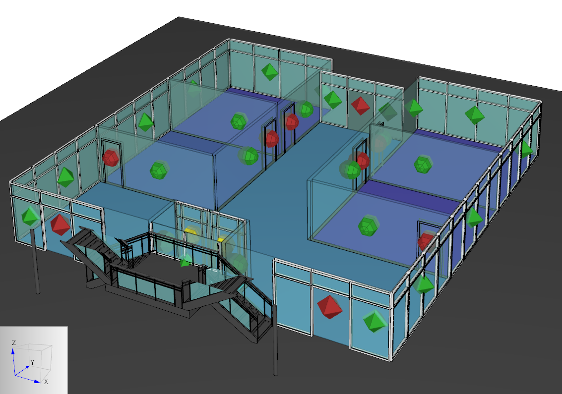
Table 2. Example Flow Element: elevator door Path Flow Element Flow Exp Flow Area (ft^2) Elevator door (closed) DOOR-EL 0.65 0.60 Switch to Perspective view to avoid missing the doors. Highlighting imported geometry groups like
Aluminumcan help to identify door locations, as done in Figure 12.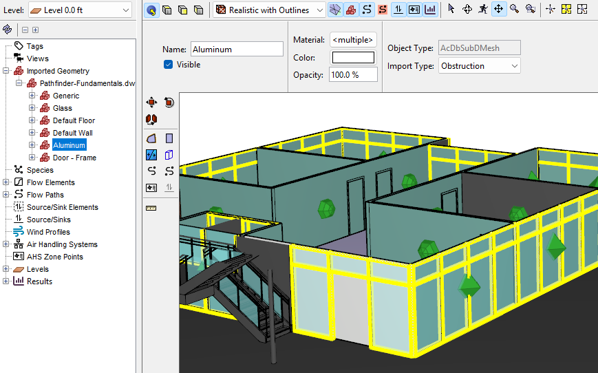
Figure 12. Perspective view of using material selection to highlight door locations while creating Flow Paths. Check that your model looks like Figure 13 and Figure 14. If there are gaps, visit the section Working with Gaps Between Zones.
We can check the area of any wall AREA/Area type Flow Path. It should correspond to the length of the wall times the first level wall height, 9 ft.
Draw the zones and Flow Paths for the second level
To draw zones and Flow Paths for the second level:
- In the Object tree, right-click
Level 9.0 ftand select Set as Active Floor. - In the View toolbar, select Top View and click Reset All.
Draw zones, taking care to adjust the room areas for the typical floor plan as in Figure 15.
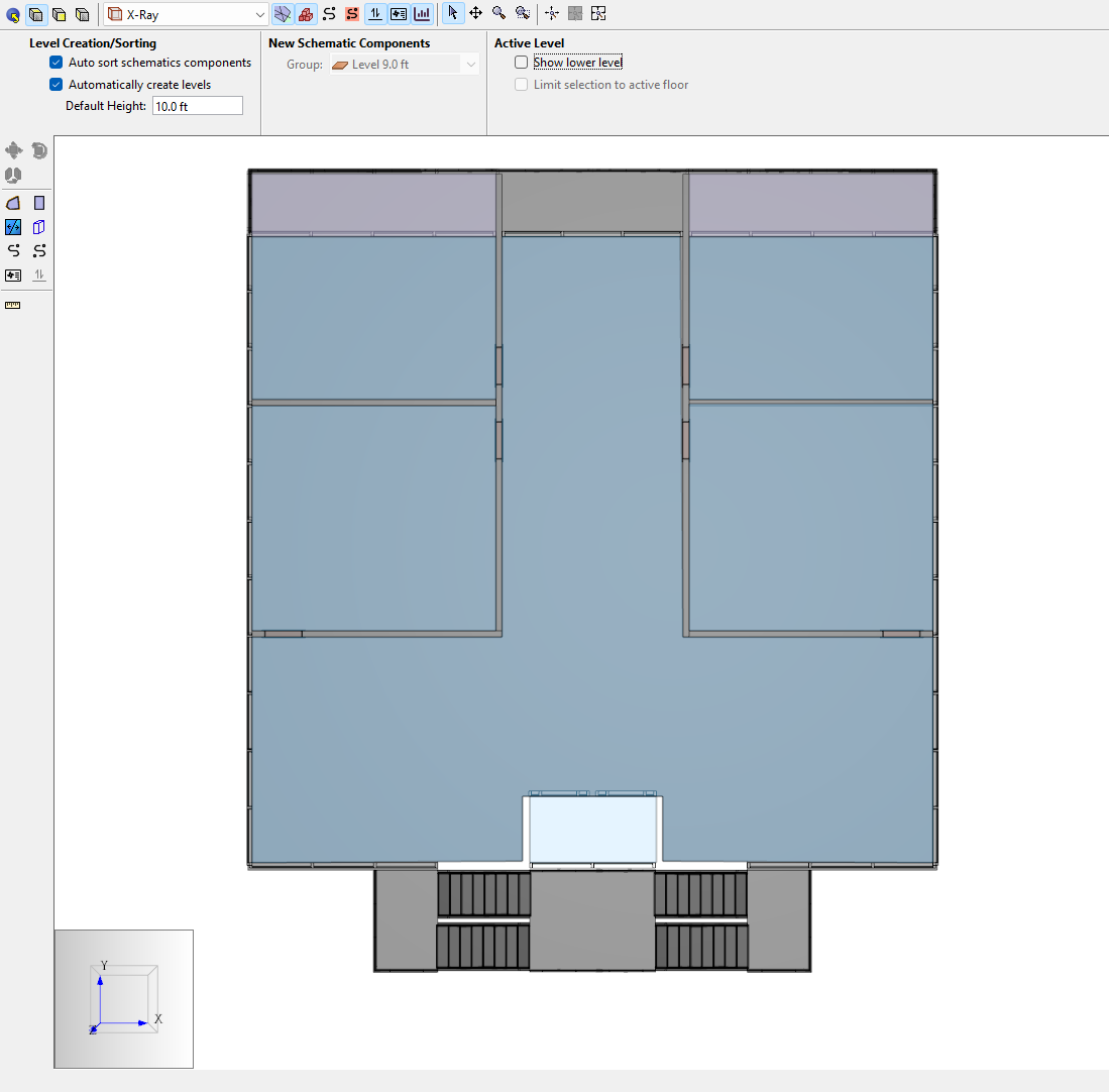
Figure 15. Top view of second level with zones and imported geometry shown. - Make the zones where there is a balcony Ceiling type rooms:
- Select the zones representing the exterior balcony portion of the second floor.
- In the Properties panel, change the Room Type from Zone to Ceiling.
- Toggle
 Show Imported Geometry OFF.
 Compare to Figure 16.
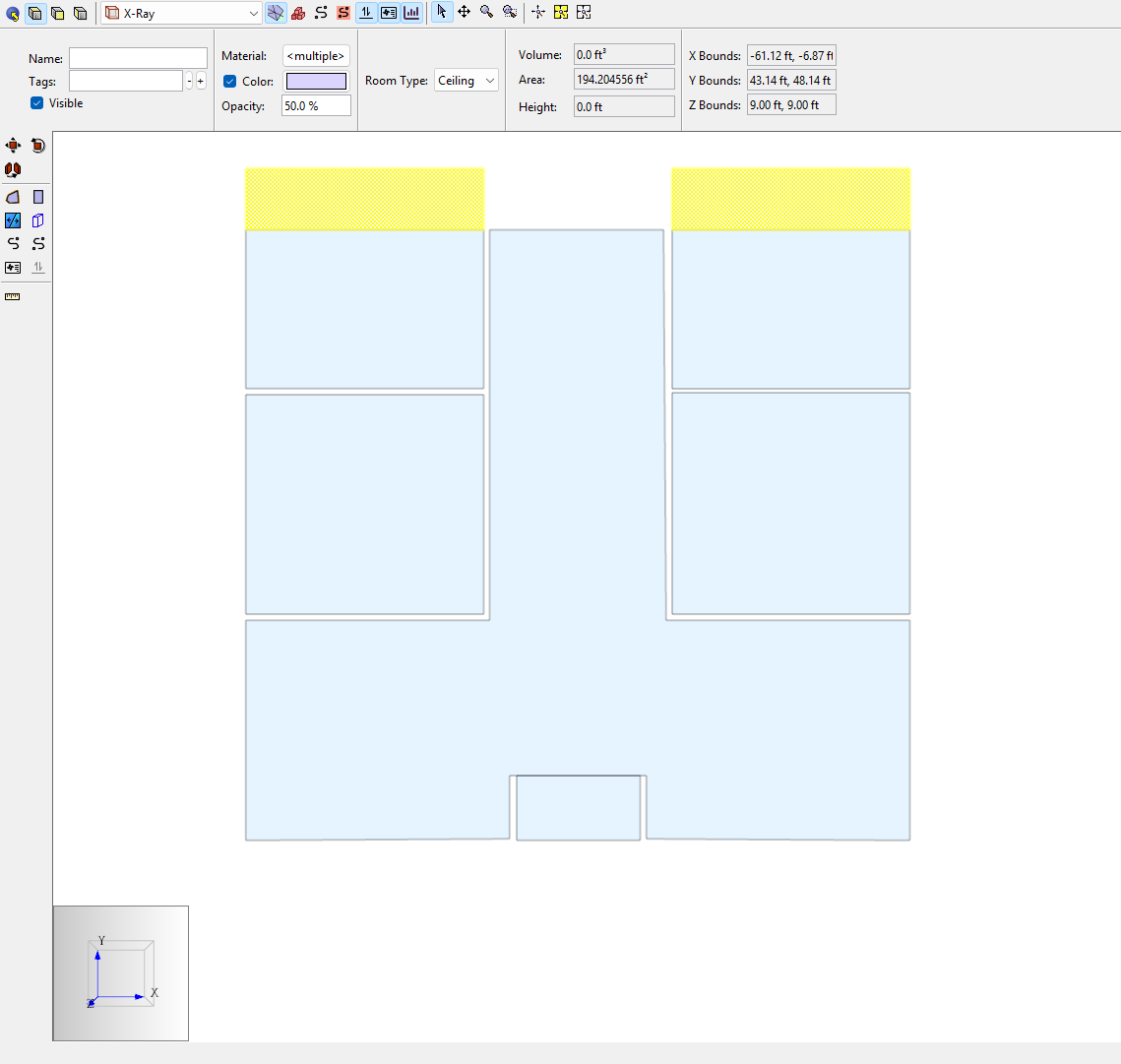
Figure 16. Second level with ceiling type zones selected (imported geometry hidden).
Add Flow Paths.
You will need to define a floor Flow Element; use Floor from the Basic First Model Tutorial, represented in Table 3.
Table 3. Example Flow Element: floor or roof Path Flow Elements Flow Exp Flow Area (ft^2) Floor or roof per ft2 Floor 0.65 1.7E-4 - Use Ventus tools to develop the appropriate network model of airflow and check your work:
- When no object is selected, toggle Show lower level ON and OFF
Toggle
Show Imported Geometry (Figure 17)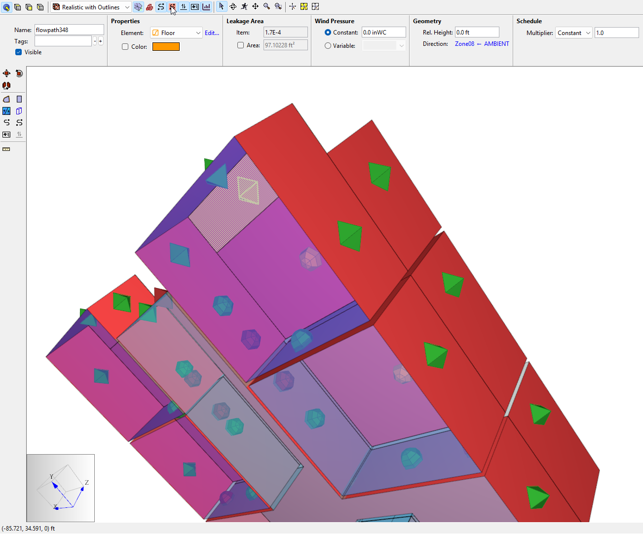
Figure 17. Toggle the Imported Geometry visibility and the Flow Path area coverage tools to understand which area values are used to calculate leakages Toggle
 Show Flow Paths and
  Show Flow Path Input Geometry (Figure 18)
Figure 18. 3D perspective view of completed first and second levels while view modes are toggled.
Copy the Typical level to define levels three through six
Create four copies of the Zone and Flow Path objects on the second level:
- Select all room-type Zones and applicable Flow Paths on
Level 9.0 ft. - Use the Move/Copy tool to create 4 copies of the objects spaced out (z = 10 ft).
Define level seven and level eight
Create one copy of the Zone objects on the sixth level:
- Select all Zone type Rooms on
Level 49.0 ft. - Use the Move/Copy tool to create 1 copy of the objects moved up 10 ft.
- Set
Level 59.0 ftas the active level. - For all zones except the elevator shaft, change the Room Type to Ceiling.
Draw the appropriate Flow Paths like in Figure 19.
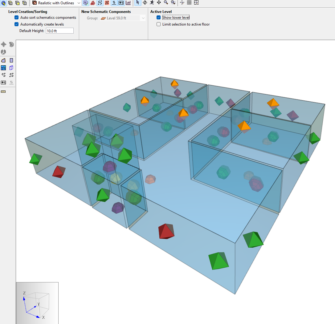
Figure 19. Level seven completed - Set
Level 68.0 ftas the active level. - Create one Ceiling type room on
Level 68.0 ftfor the elevator shaft; only include the area of the roof that covers the shaft. Draw the appropriate Flow Path like in Figure 20.
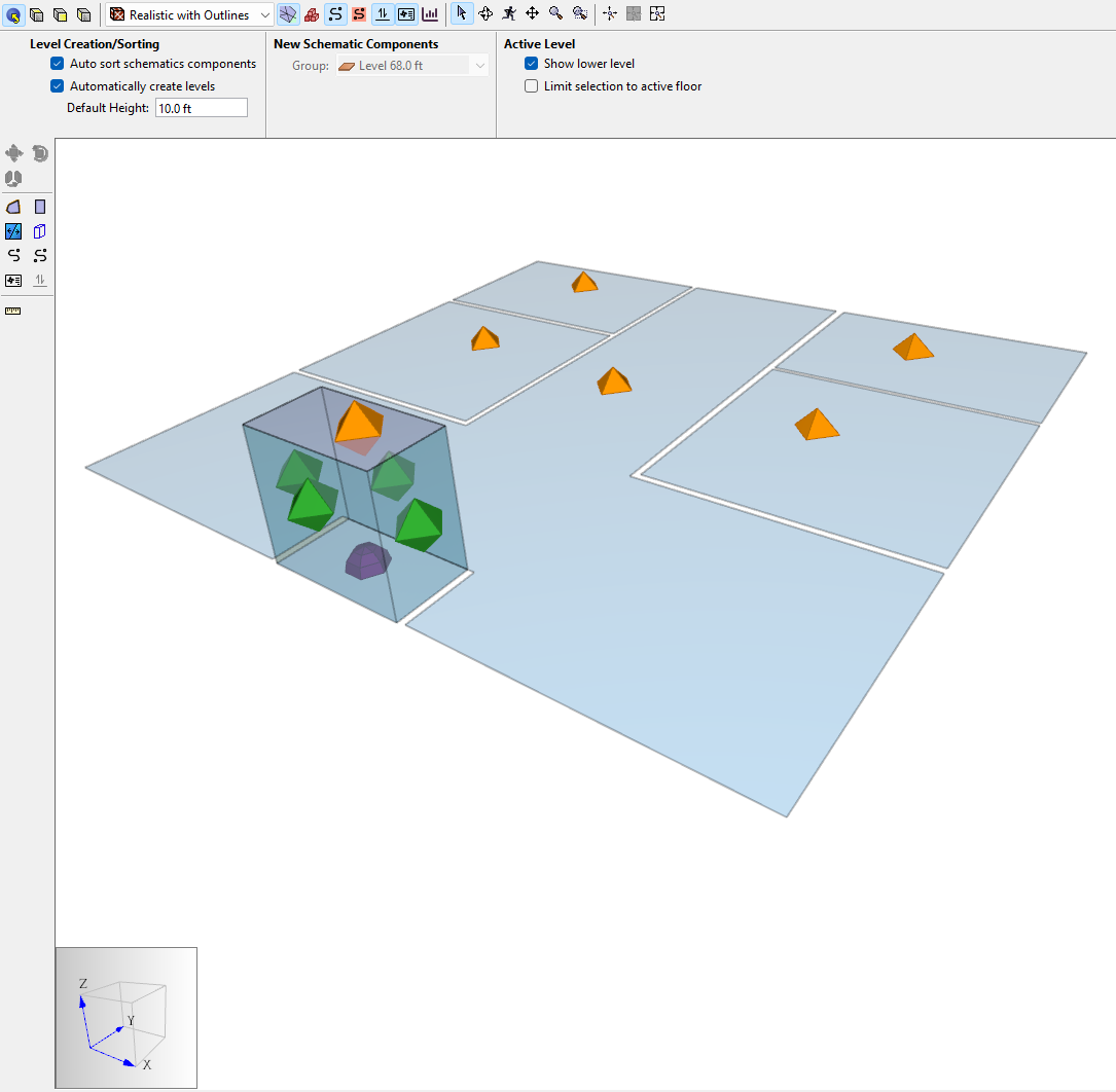
Figure 20. Level eight completed The completed model should closely resemble Figure 21
Figure 21. Full model completed
Finish the model with weather data
Proceed to modify the weather and run analysis, as desired. The following results view, Figure 23, was calculated for no-wind, Isothermal conditions (Tindoors = Tambient = 68.0 °F).
|  |
Working with Gaps Between Zones
Due to the thickness of walls in the imported 3D file, there will be gaps of Ambient volume between your zones. It is important to select the appropriate zone when creating Flow Paths with the tools in Ventus. You can accidentally link Flow Paths to Ambient gaps instead of zones, as in this extreme example:
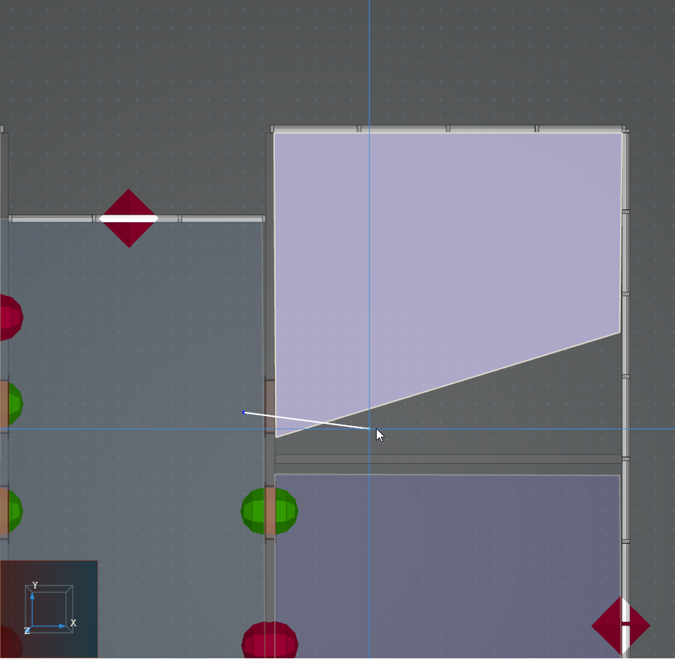
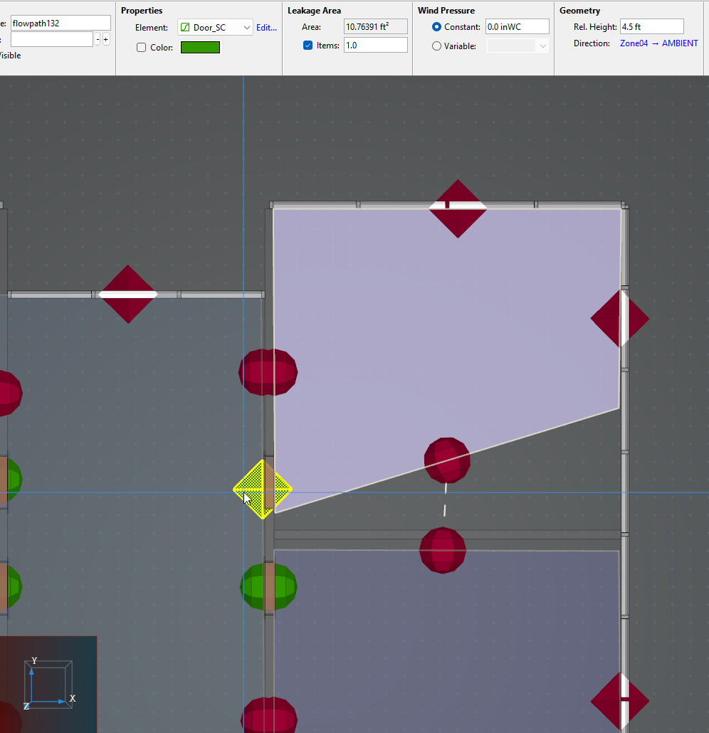
Although the creation line for the Flow Path passed through Zone10 in Figure 24, the Flow Path connects the first room, Zone04 to Ambient. The early warning of the Flow Path error is that it is a diamond body in Figure 25.
Delete the errant Flow Path and draw it properly, so that it links Zone04 and Zone10 as intended. The new Flow Path displays as a rounded body. You can verify the details by selecting it, as done in Figure 26.
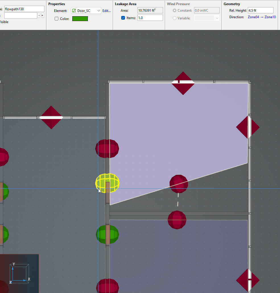
For angled walls as in Figure 26, one wall is projected onto the other to perform the area calculation. When the wall angles differ by more than 1 degree, Ventus will provide a warning in the Object tree. For more information, return to the Basic First Model tutorial.
Conclusion
This tutorial provided step-by-step instructions to define a Ventus model with 3D imported geometry.
Key points included:
- Level clipping and changes to level heights
- Modifying imported geometry settings
- Deliberate usage of Ceiling Zones
- Flow Path visualization tips
- Working with gaps between zones
To download the most recent version of Ventus, please visit the Ventus Download page. Please contact support@thunderheadeng.com with any questions or feedback regarding our products or documentation.
Related Tutorials
Modeling Contaminants
Reading Time: 7 minutes -
Contaminants
cad
flow
species
contaminants
transient
-
Contaminants
cad
flow
species
contaminants
transient
This Feature Demo details the steps to model basic Contaminants in Ventus.
Closed Door Studies
Reading Time: 6 minutes
-
smoke control
REHVA
cad
flow
This tutorial teaches the user how to perform a closed door Stairwell Pressurization study in Ventus.
Open Door Studies
Reading Time: 8 minutes
-
smoke control
REHVA
cad
flow
This tutorial teaches the user how to perform an open door Stairwell Pressurization study in Ventus.
Modeling Fire in Pyrosim
Reading Time: 3 minutes -
cad
combustion
flow
geometry
pyrolysis
-
cad
combustion
flow
geometry
pyrolysis
Tutorial demonstrating how to model a fire in Pyrosim.
(Legacy) PyroSim Fundamentals
Reading Time: 3 minutes
(Legacy) Tutorial to experience the fundamental features of PyroSim
-
presentation
cad
combustion
control
device
flow
geometry
hvac
import
material
mesh
output
pyrolysis
radiation
surf
Drawing on a 2D Image
Reading Time: 8 minutes
-
import
flow
video
This Feature Demo details the steps to create a Ventus model by drawing on a 2D image.
Modeling a Pressure Relief Vent
Reading Time: 4 minutes
-
cad
flow
geometry
hvac
Tutorial demonstrating how to model a pressure relief vent in Pyrosim.
Subway Circulation and Emergency Evacuation Using Triggers
Reading Time: 13 minutes -
public transit
venue
process
behavior
cad
queue
geometry
flow
groups
profiles
triggers
-
public transit
venue
process
behavior
cad
queue
geometry
flow
groups
profiles
triggers
Update to a Pathfinder subway station passenger movement, using queues and triggers to simulate standard circulation, then an emergency evacuation.