To follow along with this post, download the link: condo_validation.zip file.
Introduction
The eight story condominium is the third example taken from the ASHRAE Handbook of Smoke Control Engineering, Klote et al., 2012. Chapter 14 - Network Modeling and CONTAM gives background to modeling and includes four CONTAM examples.
Model Geometry
ASHRAE Model
The ASHRAE Handbook gives the following floor plans for the ground level and levels 2 through 6.
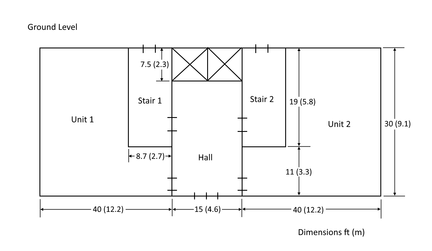
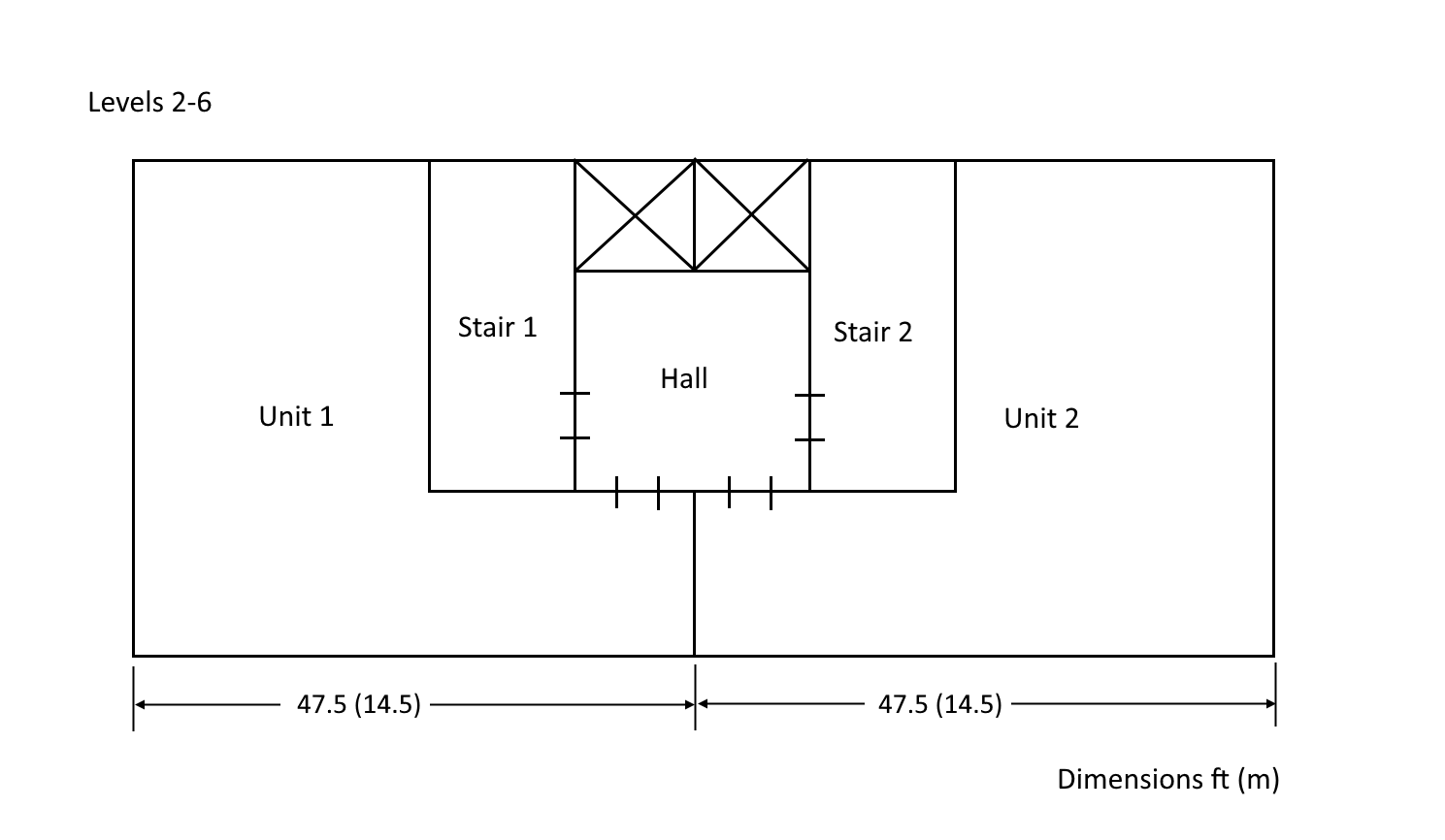
Notes:
- Drawings not to scale.
- Measurements are from the middle of the walls.
- The building is symmetrical, so not all wall dimensions are shown.
- The interior dimensions of the stairwells are 8.1 ft by 18.5 ft (2.47 m by 5.64 m).
- The interior dimensions of the hoistway are 7 ft by 14.5 ft (2.13 m by 5.64 m).
- The stairwells are to be pressurized.
- The minimum and maximum design pressure differences are 0.10 and 0.35 in H2O (25 to 87 Pa).
- The standard barometric pressure at this location is 14.3 psi (98.6 kPa).
- The floor-to-floor height is 9 ft (2.74 m)
We will simulate winter conditions as given below. The absolute pressure is 14.3 psi (CONTAM converts this to 396.218 inH2O).
| Winter Conditions | |
|---|---|
| Outdoor | -4F |
| Building | 73F |
| Stairwell | 8F |
| Summer Conditions | |
| Outdoor | 92F |
| Building | 73F |
| Stairwell | 89F |
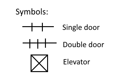
The Powerlaw Model that will be used for all flow paths is the Leakage Area option. For walls the flow area is given per unit area and for doors the flow area is per item. All doors have a total height of 7 ft, so the relative elevation is 3.5 ft.
| Path | Flow Elements | Flow Exp | Flow Area (ft^2) | Flow Area (m^2) |
|---|---|---|---|---|
| Single door (closed) | DOOR-SC | 0.65 | 0.17 | 0.0158 |
| Double door (closed) | DOOR-DC | 0.65 | 0.34 | 0.0316 |
| Elevator door (closed) | DOOR-EL | 0.65 | 0.60 | 0.0557 |
| Wall per ft^2 (m^2) | WALL-ft2/ft2 | 0.65 | 0.35E-3 | 0.35E-3 |
| Floor and roof ft^2 (m^2) | FLOOR-ft2/ft2 | 0.65 | 0.17E-3 | 0.17E-3 |
Areas and Naming Convention
In the ASHRAE problem definition, wall and floor areas are given rounded to the nearest integer. These rounded values are then used when building the CONTAM model. But, since Ventus uses the true wall dimensions when calculating wall and floor areas, we will use values to three decimal points when building the CONTAM model. This will allow us to accurately compare the CONTAM results to the Ventus calculations
The figures below give wall areas in both metric and Imperial units. Note that the values are presented metric first, then Imperial. The figures also include names for each wall and floor. When making the Ventus model we will, in most cases, just use the default names given by Ventus. However, for the walls and doors around Stair 1, we will give specific names so that we can better access the results.
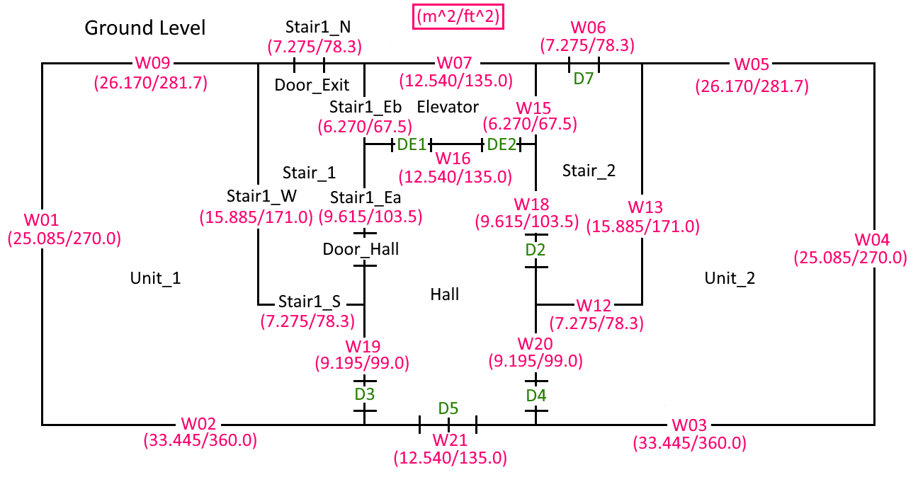
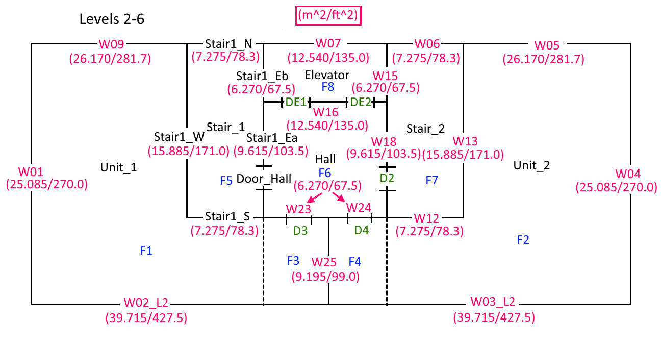
The floor areas are:
| Floor | Area (ft^2) | Area (m^2) |
|---|---|---|
| F1 | 1034.70 | 96.125 |
| F2 | 1034.70 | 96.125 |
| F3 | 82.5 | 7.665 |
| F4 | 82.5 | 7.665 |
| F5 | 165.30 | 15.355 |
| F6 | 172.50 | 16.025 |
| F7 | 165.30 | 15.355 |
| F8 | 112.50 | 10.450 |
The wall and floor area calculations are given in the following spreadsheet. ventus_validation3_wall_areas_calculation.zip file.
Basic Model Parameters
Start by entering the basic model parameters:
- On the Menu shortcuts, click EN to select Imperial units. Note: We use Imperial since that is the system used by the ASHRAE example.
- On the Analysis menu, click Simulation Parameters. Set the Default Zone and Junction Temperature to 73 F.
- On the Model menu, click Weather and Wind. On the Weather tab, click to edit the Ambient Temperature and in the table type -4 F.
- In the Weather and Wind dialog change the Absolute Pressure to 396.218 inWC. Click OK to close the dialog.
- In the Ribbon, change the Default Height to 9 ft. Accept the change to Level 0.0.
- In the View toolbar, select Realistic with Outlines.
- Save the model as condo_validation.
Draw the Ground Floor
We start by drawing the ground level. There are different ways to do this. In the following description we will draw each zone explicitly. But an alternate approach is to draw one big zone corresponding to the outer boundary and then draw the smaller zones on top of the big zone. The big zone will be subdivided as you draw the smaller zones.
- On the View menu, click Edit Snap Grid. Type 2.5 ft and click OK. This grid spacing will help us quickly draw most of the zones.
- In the View toolbar, select the Top View.
- We will locate the origin at the bottom center of the model.
- Double-click the Add a Rectangular Room tool and draw the ground level hall and elevator.
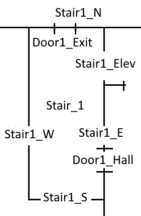
- Next draw the stairs. When drawing the left stairs, it is easiest to click on the upper right corner and then repeatedly press Tab, manually type the locations of X2 (-16.2 ft) and Y2 (11.0 ft), then tab to select Create and press Enter. The figure below shows the coordinates of Stair 1. In a similar manner, draw Stair 2. Hovering the mouse in the 3d window after entering a coordinate will clear out the value you entered. To be able to tab and enter coordinates, you’ll need to keep the mouse in the property panel area. .Coordinates of Stair 1. image::ventus-scrn-ventus-validation3-coordinates-of-stair1-ground.png["Coordinates of stair 1.",500]
- To draw Unit 1 and Unit 2 double-click the Add a Polygonal Room tool and click on the corners. Right-click to close the polygon.
- Select the Stair 1 and Stair 2 zones and name them.
- At the same time, select Temperature and type the value both stairs of 8 F.
Create the Flow Elements
Before defining the flow paths, we first create the flow Flow Elements. as defined in the table 2 above.
- In the Tree view, double-click Flow Elements.
- Select the existing AREA/Item flow element and then click Duplicate. Type the Name DOOR-SC. Click OK to close the Duplicate Flow Element dialog and create the new flow element.
- Set the Leakage Area value to 0.17 ft^2. Note that door leakage is specified Per Item, that is, the total leakage area is input. The remaining default values are appropriate. Click Apply.
- Repeat for the DOOR-DC double door closed. The Leakage Area is 0.34 ft^2 and click to change the Color to a magenta.
- Repeat for the DOOR-EL elevator door closed. The Leakage Area is 0.60 ft^2 and click to change the Color to a yellow.
- Select the existing AREA/Area flow element and then click Duplicate. Type the name WALL-ft2/ft2 with a Leakage Area of 0.35E-3 ft2/ft2.
- Repeat for the FLOOR-ft2/ft2 flow element with a Leakage Area of 0.17E-3 ft2/ft2 and change the color to orange.
Add Flow Paths to the Ground Floor
First we add all the wall leakage flow paths:
- In the View toolbar, select the Top View.
- On the View menu, unselect Show Snap Grid. This turns of snapping to the grid points.
- In the Model toolbar, double-click the two point flow path tool.
- In the Ribbon, select the WALL-ft2/ft2 flow element.
- The default elevation will be half the height of the level. You can change this later if needed.
- Now, with a click and drag create all 20 wall leakage flow paths. Note that we do not add a wall flow path for the elevator doors. Expand Flow Paths in the tree to verify you have 20 flow paths.
Now add the door leakage flow paths:
- Double-click the two point flow path tool.
- In the ribbon, select the Door-SC flow element. With a click and drag create the six single doors. Select these doors and in the ribbon set the Rel Height to 3.5 ft.
- In the ribbon, select the Door-DC flow element. With a click and drag create the one double door. Select this door and in the ribbon set the Rel Height to 3.5 ft.
- In the ribbon, select the Door-EL flow element. With a click and drag create the two elevator doors. Select these doors and in the ribbon set the Rel Height to 3.5 ft.
- Select and rename the wall flow paths and doors that access Stair 1 as shown below.
- Save the model.
Second Level
We will copy the first level to the second level, then modify the second level.
- With the Select/Edit tool, click and drag to select everything on the ground level.
- Select the Copy/Move tool. In the ribbon, select Copy Mode. Make 1 copy. In the Move Z box type 9 ft. Click Copy/Move.
- Select the Perspective view and 3D Orbit Navigation and click the Reset All button.
Now we will modify the second level.
- Select Top View.
- To edit Level 9.0 (Level 2), in the View toolbar select the X-Ray option and in the Ribbon select Show lower level. In the Tree, right-click on Level 9.0 and click Set as Active Level. You now see Level 9.0 and the level below, but when you delete or add features, you will only change the Active Level.
- In the View menu, select Show Snap Grid.
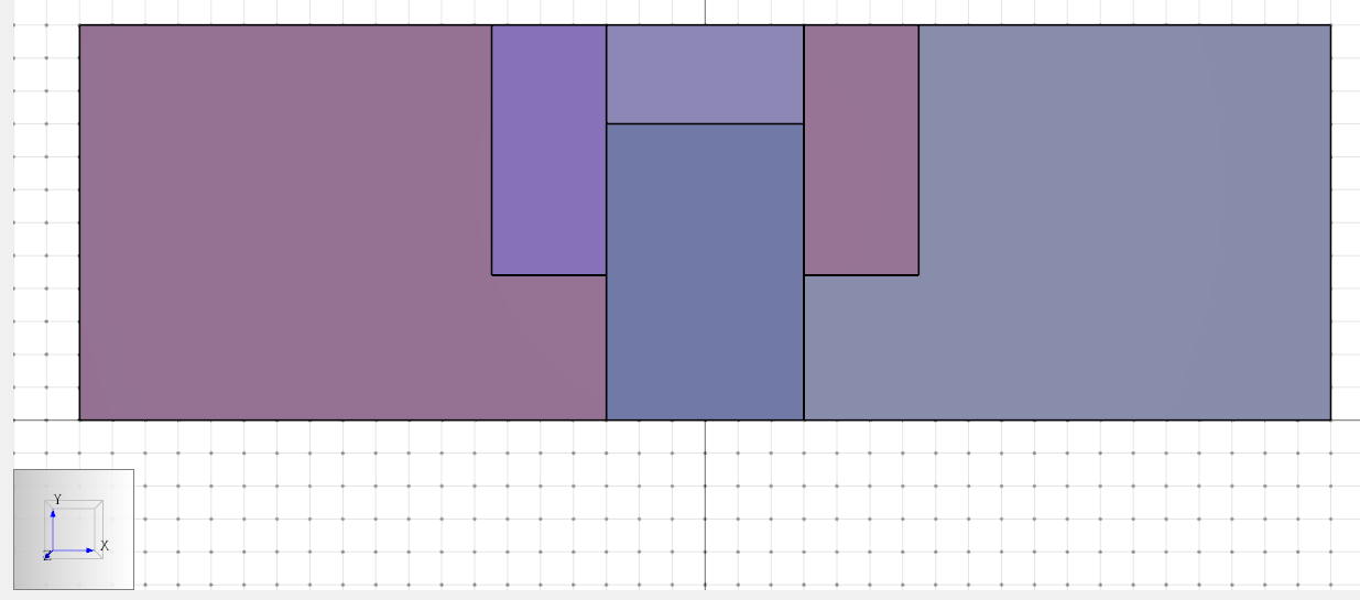
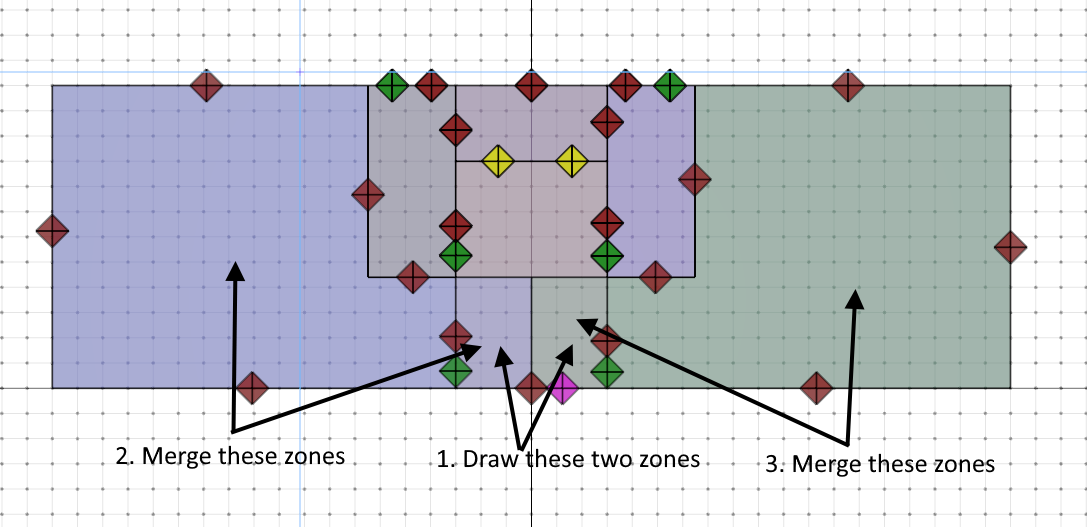
- Double-click the Rectangular Room tool and draw two zones that split the lower part of the center hallway. Click first at the corner of the stairway and then click at the center of the model. See below.
- Now select Unit 1 and the left small zone you just drew. Right-click and Merge Rooms.
- Repeat for Unit 2.
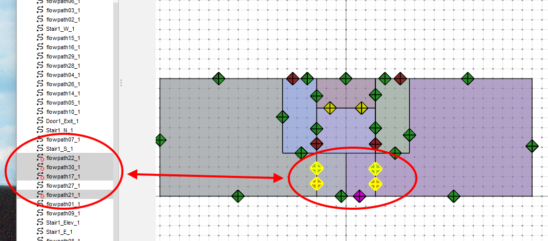
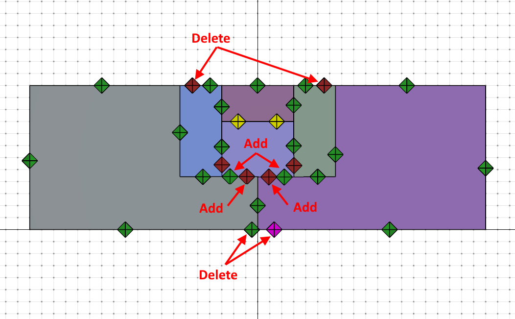
- When the two rooms were merged, the original flow paths between those rooms are no longer valid. This is indicated by a red X in the tree. Expand the tree, select the four invalid flow paths, and delete them.
It will help if we view only the second level. In the View toolbar select the Realistic with Outlines option and in the Ribbon unselect Show lower level. Finish updating the flow paths:
- Add a WALL-ft2/ft2 flow path between Unit_1 and Unit_2.
- Add two WALL-ft2/ft2 flow paths between Unit_1 and Unit_2 and the hall.
- Delete the exit doors from the stairways.
- Delete the wall leakage and exit door flow paths from the previous hall.
- Add Door-SC flow paths from the hall to the individual units. Remember to set the Relative Height to 3.5 ft.
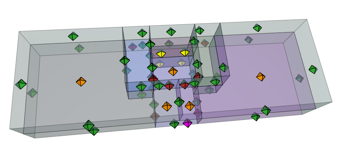
Next we add the floor leakage to the rooms below. Let us do this working in the Perspective View.
- Click Perspective View.
- In the View toolbar, select X-Ray mode and Show lower level select.
- Double-click the single click flow path tool and in the Element dropdown, select Floor.
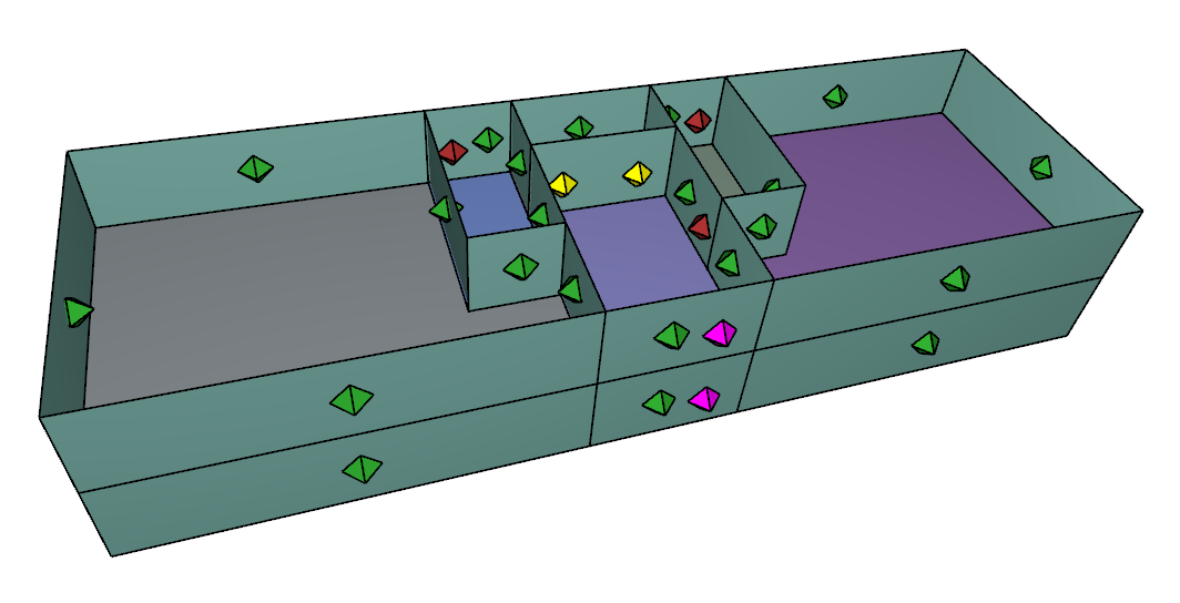
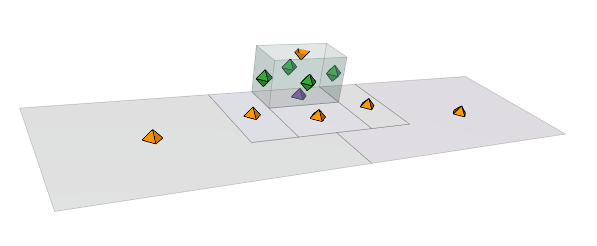
- Add five flow paths to the rooms below, two in each unit and one in the hall. These are the golden flow paths shown in the figure below. Unit 1 and Unit 2 have two flow paths each because one connects to the Unit below and one to the Hall below.
Next we will add the stairwell and elevator shaft flow paths. We first must add these as flow elements. The stairwells have an area of 150 ft^2, a people density of zero, and closed tread. The elevator shaft has an area of 102 ft^2, a perimeter of 43 ft, and a roughness of 0.33 ft.
- In the tree, double-click Flow Elements.
- Select STAIRWELL and click Duplicate. Type the name Stair and click OK.
- Set the distance between levels to 9 ft and the cross-sectional area to 150 ft^2. Click Apply.
- Select SHAFT and click Duplicate. Type the name Elev and click OK.
- Set the distance between levels to 9 ft, cross-sectional area to 102 ft^2, perimeter to 43 ft, and roughness to 0.33 ft. Click Apply.
- Close the Edit Flow Elements dialog.
Now add the flow paths.
- Select the single point flow path tool, set the Element to Stair, and click to add flow paths to both stairwells.
- Change the Element to Elev and add the elevator shaft flow path.
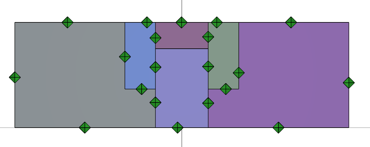
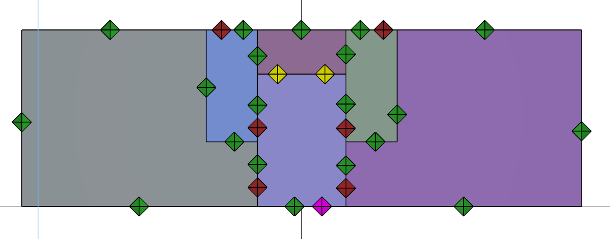
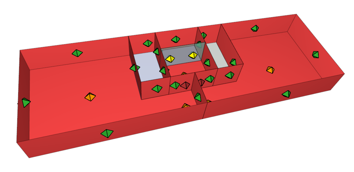
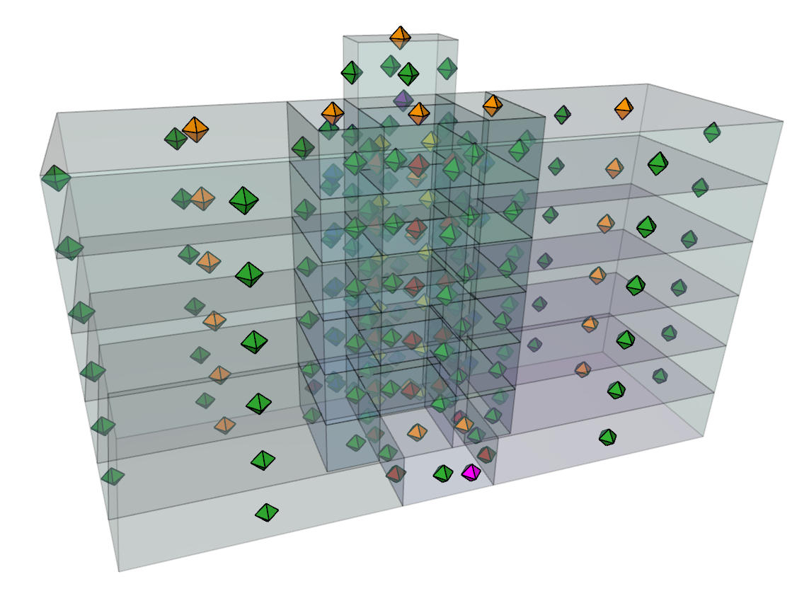
- Your model should now look like Figure 15.
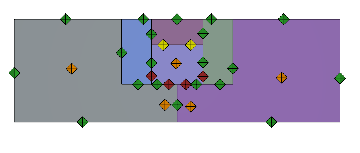
Verify the flow area calculations. In the View Toolbar select the Show Flow Path Coverage tool. This displays the calculated wall flow areas in red. As you can see, all walls and floors with Area per Unit Area flow elements are displayed. You can select a flow path to highlight the area associated with that specific path.
Third Level
We will now copy Level 2 (Level 9.0 ft) to create a third level.
- In the Ribbon, turn off Show lower level, then in the Tree right-click Level 9.0 and Set as Active Level. You should only see one level.
- Using the Select/Edit Objects tool, click and drag to select all zones and flow paths.
- Select the Copy/Move tool.
- In the ribbon, select Copy Mode. Make 1 copies.
- In the Move Z box type 9 ft.
- Click Copy/Move to create the third level.
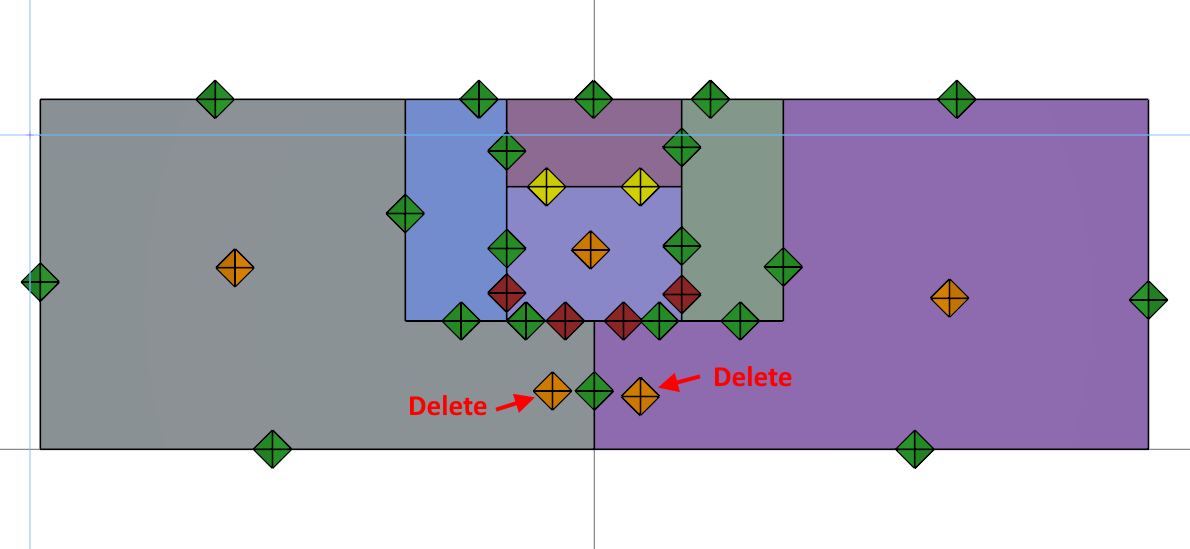
We want to copy the third level to create all eight floors, but first we must delete two extra floor flow paths.
- Right-click Level 18.0 and Set as Active Level.
- Delete the two flow paths shown below.
- Select the remaining floor flow path in Unit 1 and notice that the Area is 1117.2 ft^2. This is the correct area for the leakage from Unit 1 to the level below. Ventus automatically updated the flow area when we made the third level, but we had to delete the extra flow paths or we would have accidentaly doubled the computational area input.
Create All Eight Levels
We will now copy Level 18.0 five times to create the upper levels of the model.
- Make sure Show lower level is not selected, then in the tree, right-click Level 18.0 and Set as Active Level.
- Using the Select/Edit Objects tool, click and drag to select all zones and flow paths.
- Select the Copy/Move tool.
- In the ribbon, select Copy Mode. Make 5 copies.
- In the Move Z box type 9 ft.
- Click Copy/Move.
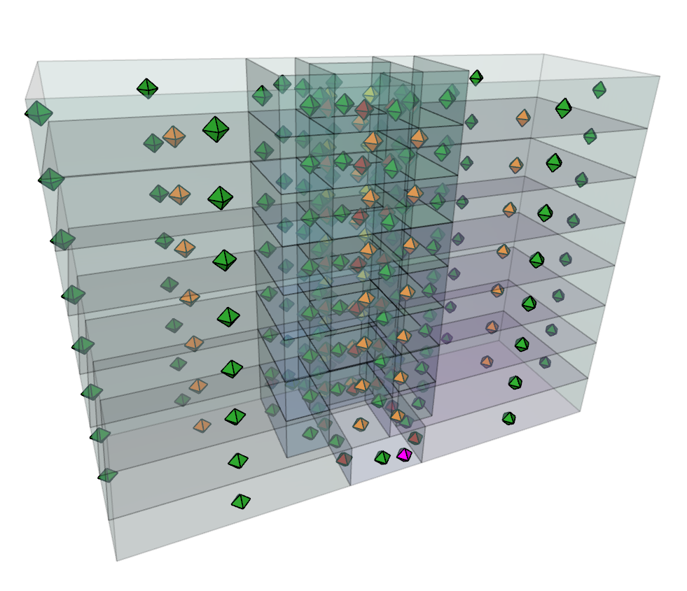
- Select the Perspective view and click the Reset All button.
- Select Realistic with Outlines as the display mode.
- In the tree, right-click Levels and select Show.
-In the tree, select Levels and change Opacity to 30%.
Edit Roof
The elevator shaft extends above the building and is defined by levels seven and eight. Level eight (Level 63.0 ft) defines the roof of the elevator shaft. Level seven (Level 54.0 ft) defines the top level of the elevator shaft and the roof for most of the building.
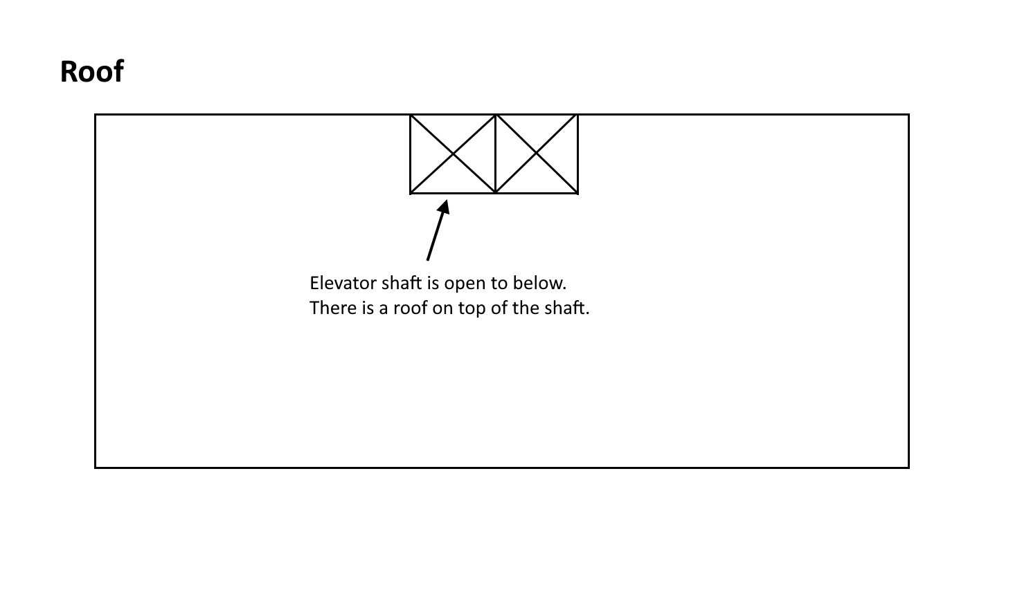
In Ventus, we define roof flow paths by including a zone that represents the ceiling above the room.
- Right-click Level 63.0 and Set as Active Level. Make sure Show lower level is turned off.
- In the Top View, delete all zones except for the elevator zone and delete all flow paths.
- Select the elevator zone and change the Room Type to Ceiling.
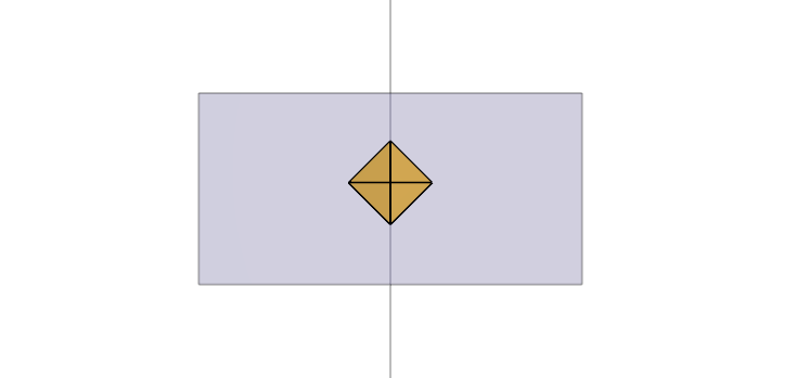
- Use the single click flow path tool to add a Floor flow path.
- Your model should look as shown below. The flow path connects the ceiling of the elevator shaft to ambient.
We now must make similar changes to represent roof leakage for the top of Level 45.0 (Level 6 in the model).
- Right-click Level 54.0 and Set as Active Level.
- In the Top View, select all zones except the elevator and change the Room Type to Ceiling.
- Clean the model by deleting all the unused wall flow paths. These will be all the invalid flow paths indicated in the Tree.
- Delete the two elevator doors.
- Using either the single point or two point flow path tool, add a WALL flow path to the wall that previously had the elevator doors.
- Delete the two stairwell flow paths and replace with floor flow paths.
- When finished, your model should look like this.
Add Supply
We will now add a supply to pressurize the stairwells. In Ventus we assume a simple Air Handling System (AHS), so the user only needs to define the supply or return location in the model.
- Right-click Level 9.0 (Level 2) and Set as Active Level.
- Select the AHS tool, make sure the Type is Supply, and set the Design Flow Rate to 2500 scfm.
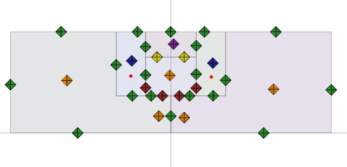
- Add supplies to both stairwells. They will be indicated by red dots.
Run Simulation
We are now ready to run the simulation.
- Save the model.
- Click to run the simulation.
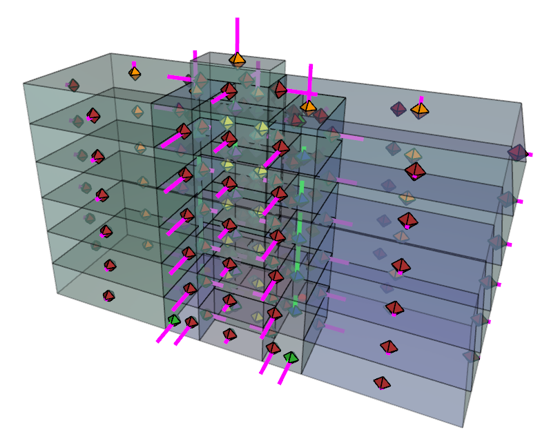
When finished, the results will be displayed with arrows.
Explore Results
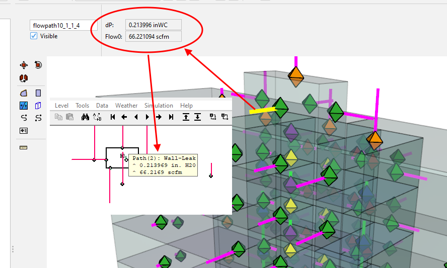
Click a flow path to display the pressure difference and flow rate. Here we compare results from the Ventus model with CONTAM. Notice that the results are identical to the fifth significant figure. The small difference is due to the different precisions when writing the input prj file. In most cases, Ventus uses more significant figures.
Results - Door Pressure
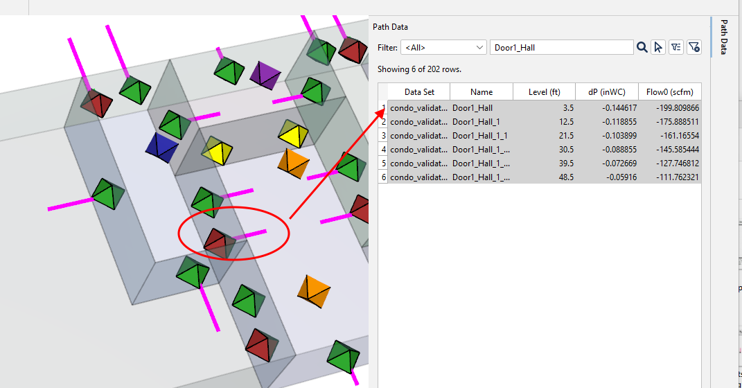
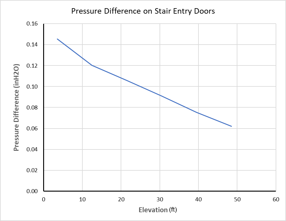
We will first make a plot of pressure difference on the doors as a function of height. Recall that on the ground level, we named the door between the stair and the hall Door1_Hall. We will use the name to search the results.
- On the right of the screen, click Path Data. This displays all results for the simulation.
- To filter to just the door results, in the search box enter Door1_Hall.
- You can now select the data and make a graph of the results. Note that whether the pressure difference is reported as positive or negative depends on the direction used when defining the flow path. The display of the results in the 3D View Window is always drawn showing the direction of pressure difference or flow.
Work with Results File
If desired, you can also work with zone and flow path data in a spreadsheet, as described in detail in the Basic First Model tutorial.
The results data can now be compared to the expectations of the ASHRAE Eight-Story Condominium example and the results of an equivalent CONTAMW simulation for verification. The ZIP file linked at the top of this document contains CONTAMW PRJ input file to facilitate this work.
Related Tutorials
Fourth example from the ASHRAE Handbook of Smoke Control Engineering, Klote et al., 2012. Chapter 14 of the handbook, Network Modeling and CONTAM
An example from the ASHRAE Handbook of Smoke Control Engineering, Klote et al., 2012. Chapter 14 of the handbook, Network Modeling and CONTAM
Second example from the ASHRAE Handbook of Smoke Control Engineering, Klote et al., 2012. Chapter 14 of the handbook, Network Modeling and CONTAM
This tutorial teaches the user how to model door state changes in Ventus
(Legacy) Tutorial to experience the fundamental features of PyroSim
Video tutorial demonstrating the variables that may have an effect on evacuation time from aircraft cabins.
To demonstrate basic Ventus capabilities, we will model a simple six-story building for winter and summer conditions.
Tutorial demonstrating how to make stairs in Pathfinder