To follow along with this post, download the link: wind-validation.zip file.
Introduction
The wind example is the second example taken from the ASHRAE Handbook of Smoke Control Engineering, Klote et al., 2012. Chapter 14 of the handbook, Network Modeling and CONTAM, gives background to modeling and includes four CONTAM examples.
Model Geometry
ASHRAE Model
The ASHRAE Handbook gives the following description of Example 14.2 Wind. This demonstrates the use of CONTAM to calculate the pressures produced by wind on a simple model.
The building geometry is shown below.
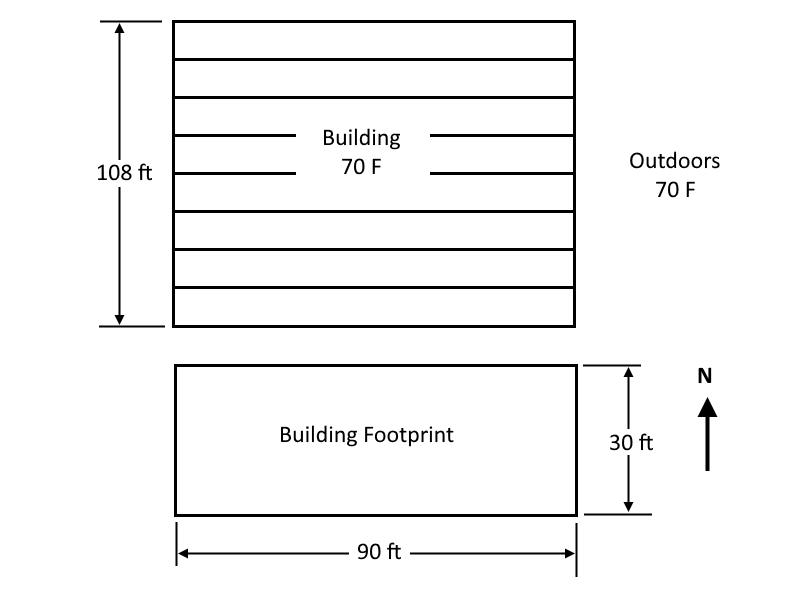
Notes:
- The wind speed is 23 mph from the north.
- The leakage between floor is 0.3 ft^2.
- The leakage of the east and west walls are both 0.5 ft^2.
- The leakage of the north and south walls are both 1.5 ft^2.
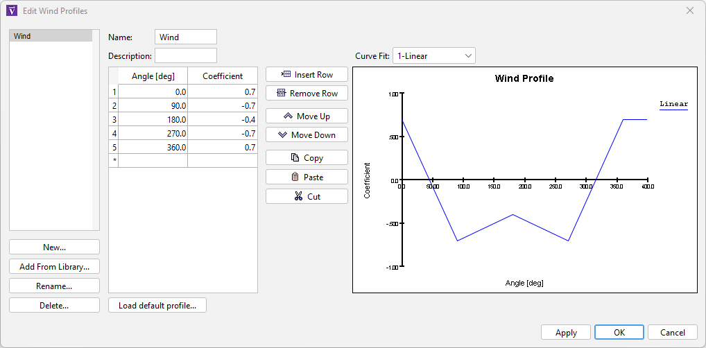
The pressure coefficients in terms of azimuth angle for a north wind are given below.
| Wall Facing | Azimuth Angle | Coefficient |
|---|---|---|
| North | 0 | 0.7 |
| East | 90 | -0.7 |
| South | 180 | -0.4 |
| West | 270 | -0.7 |
Basic Model Parameters
Start by entering the basic model parameters:
- On the top toolbar, click EN to select US Customary units.
- On the Analysis menu, click Simulation Parameters. Set the Default Zone and Junction Temperature to 70 F.
- On the Model menu, click Weather and Wind. On the Weather tab, click to edit the Ambient Temperature and in the table type 70 F.
- In the Ribbon, change the Default Height to 12 ft. Accept the change to Level 0.0.
- In the View toolbar, select Realistic with Outlines.
- Save the model as wind_validation.
Wind Parameters
The wind will be from the north at 23 mph.
- On the Model menu, click Weather and Wind.
- On the Weather tab, change the Wind Speed to 33.7333 ft/s.
- On the Wind tab, change the Roof or Wall Height to 108 ft. Click OK.
- In the tree, double-click Wind Profiles. Click New and type the name Wind. Click OK.
- The default Ventus values match the ASHRAE example. Click OK.
Draw the Ground Floor
We start by drawing the ground level.
- On the View menu, click Edit Snap Grid. Type 5 ft and click OK. This grid spacing will help us quickly draw the zones.
- In the View toolbar, select Top View.
- Click the Add a Rectangular Room tool and draw a 90 ft x 30 ft zone with the lower left corner at the origin.
- On the View toolbar, click Reset All.
- Select the zone and name it Room.
Create the Flow Elements
Before defining the flow paths, we first create the flow Flow Elements. In this example, the total leakage area is given.
- In the Tree view, double-click Flow Elements.
- Select the existing ORIFICE flow element and click Duplicate. Type the Name Short wall. Click OK.
- Set the Cross-Sectional Area value to 0.5 ft^2. Change the Discharge Coefficient to 0.65.
- Click on the color and change to red. Click Apply.
- Select the Short wall flow element you just made and click Duplicate. Type the Name Long wall. Click OK.
- Set the Leakage Area value to 1.5 ft^2. The long wall has three times the flow of short wall.
- Click on the color and change to green. Click Apply.
- Select the Short wall flow element and then click Duplicate. Type the Name Floor. Click OK.
- Set the Leakage Area value to 0.3 ft^2. This defines the total leakage area for the floor. Click on the color and change to orange.
- Click OK to close the Edit Flow Elements dialog.
Add Flow Paths to the Ground Floor
Two conditions must be met for Ventus to add the effect of wind pressure to a flow path:
- The flow path must connect to ambient.
- The Wind Pressure for the flow path must be Variable and a wind profile selected.
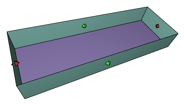
Add leakage to the walls:
- Double-click the two point flow path tool.
- In the ribbon, select the Short wall flow element. For Wind Pressure select Variable and in the dropdown select Wind. To add the flow paths, click and drag across the two short walls.
- In the ribbon, select the Long wall flow element. For Wind Pressure select Variable and in the dropdown select Wind. Click and drag across the two long walls.
- Select the Perspective View and 3D Orbit Navigation, click Reset All. Spin the model.
Second Level
We will copy the first level to the second level, then modify the second level.
- With the Select/Edit tool, click and drag to select everything on the ground level.
- Select the Copy/Move tool. In the ribbon, select Copy Mode. Make 1 copy. In the Move Z box type 12 ft. Click Copy/Move.
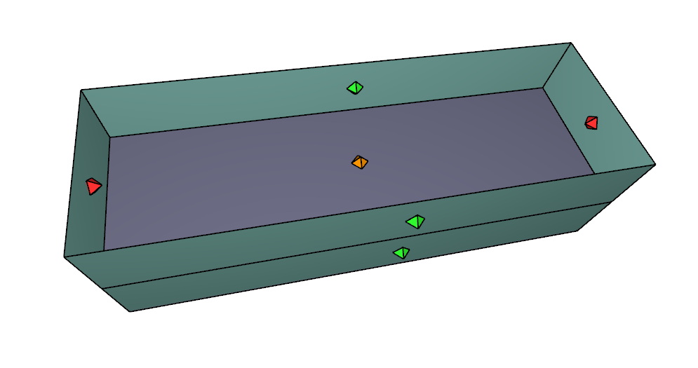
Next we add the floor leakage to the rooms below.
- Right-click on Level 12.0 and click Set as Active Floor. Click Perspective View.
- Select the single click flow path tool and in the Element dropdown, select Floor.
- Click on the floor to add the flow path.
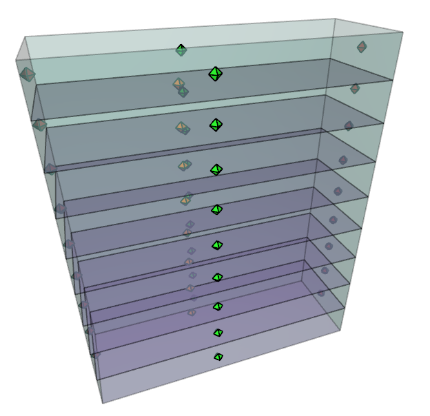
Create All Nine Levels
We will now copy Level 12.0 seven times to create the upper levels of the model.
- Make sure Show lower level is not selected, then in the tree, right-click Level 12.0 and Set as Active Floor.
- Using the Select/Edit Objects tool, click and drag to select all zones and flow paths.
- Select the Copy/Move tool.
- In the ribbon, select Copy Mode. Make 7 copies. In the Move Z box type 12 ft. Click Copy/Move.
- Select the Perspective View and 3D Orbit Navigation.
- In the tree, right-click Levels and select Show All.
- In the tree, select Levels and change Opacity to 50%.
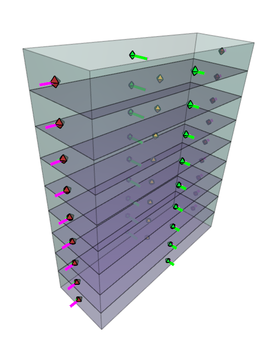
Run Simulation
We are now ready to run the simulation.
- Click to run the simulation.
When finished, the results will be displayed with arrows. Because the only driving force for leakage is the wind, CONTAM calculates all floors with identical results. Note that the leakage flows into the building on the north wall and out the east, west, and south walls.
Explore Results
Click to select a flow path. The pressure difference and flow rate for the selected flow path will be displayed in the property editor ribbon.
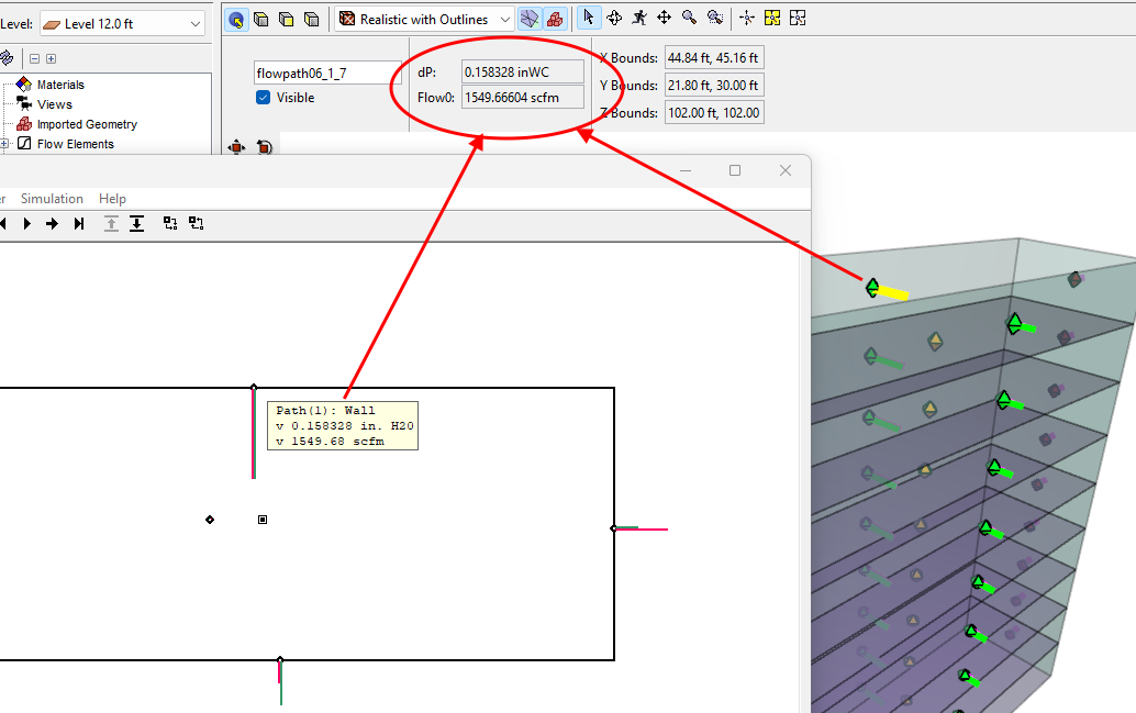
The results data can now be compared to the expectations of the ASHRAE wind problem and the results of an equivalent CONTAM simulation for verification. The ZIP file linked at the top of this document contains CONTAM PRJ input file to facilitate this work.
Related Tutorials
An example from the ASHRAE Handbook of Smoke Control Engineering, Klote et al., 2012. Chapter 14 of the handbook, Network Modeling and CONTAM
Third example from the ASHRAE Handbook of Smoke Control Engineering, Klote et al., 2012. Chapter 14 of the handbook, Network Modeling and CONTAM
This tutorial teaches the user how to model door state changes in Ventus
(Legacy) Tutorial to experience the fundamental features of PyroSim
Video tutorial demonstrating the variables that may have an effect on evacuation time from aircraft cabins.
To demonstrate basic Ventus capabilities, we will model a simple six-story building for winter and summer conditions.
Tutorial demonstrating how to model jet fans in Pyrosim.
Tutorial demonstrating how to model a pressure relief vent in Pyrosim.