To follow along with this post, download the link: stack-validation.zip file.
Introduction
The stack effect is the first example taken from the ASHRAE Handbook of Smoke Control Engineering, Klote et al., 2012. Chapter 14 of the handbook, Network Modeling and CONTAM, gives background to modeling and includes four CONTAM examples.
Model Geometry
ASHRAE Model
The ASHRAE Handbook gives the following description of Example 14.1 Stack Effect. This simple model shows the effect of a warm shaft with cold ambient temperatures.
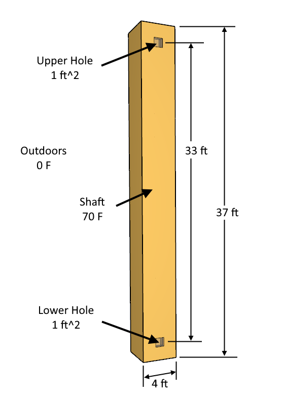
Basic Model Parameters
Start by entering the basic model parameters:
- On the top toolbar, click EN to select Imperial units.
- On the Analysis menu, click Simulation Parameters. Set the Default Zone and Junction Temperature to 70 F.
- On the Model menu, click Weather and Wind. On the Weather tab, click to edit the Ambient Temperature and in the table type 0 F.
- In the Ribbon, change the Default Height to 37 ft. Accept the change to Level 0.0.
- In the View toolbar, select Realistic with Outlines.
- Save the model as shaft_validation.
Draw the Shaft
We start by drawing the ground level.
- On the View menu, click Edit Snap Grid. Type 1 ft and click OK. This grid spacing will help us quickly draw the zones.
- In the View toolbar, select Top View.
- Click the Add a Rectangular Room tool and draw a 4 ft x 4 ft zone with the lower left corner at the origin.
- On the View toolbar, click Reset All.
- On the View toolbar, select Perspective View, pick 3D Orbit Navigation, and click Reset All.
- Select the zone and name it shaft_validation.
Create the Flow Element
Before defining the flow paths, we first create the Flow Elements. In this example, the total leakage area is given.
- In the Tree, double-click Flow Elements.
- Select the existing ORIFICE flow element and click Duplicate. Type the Name Opening. Click OK.
- Set the Cross-Sectional Area value to 1.0 ft^2. Change the Discharge Coefficient to 0.65.
- Click OK to close the Edit Flow Elements dialog.
Add Flow Paths
Add the opening flow path to the shaft:
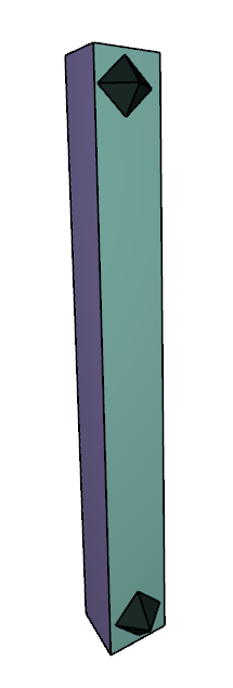
- On the View toolbar, select Perspective View.
- Double-click the single point flow path tool.
- In the ribbon, select the Opening flow element. Add two flow paths, one near the bottom of the stack and one near the top. Press ESC to unselect the flow path tool.
- Select the lower flow path and change the Rel. Height to 2 ft.
- Select the upper flow path and change the Rel. Height to 35 ft.
Run Simulation
We are now ready to run the simulation.
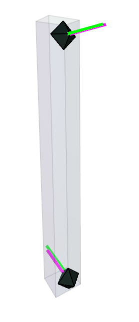
- In the top toolbar, click to Run Simulation.
When finished, the results will be displayed with arrows. To see inside the model, select the shaft and change the Opacity to 20. The flow is in at the bottom and out at the top.
Explore Results
Click to select a flow path. The pressure difference and flow rate for the selected flow path will be displayed in the property editor ribbon.
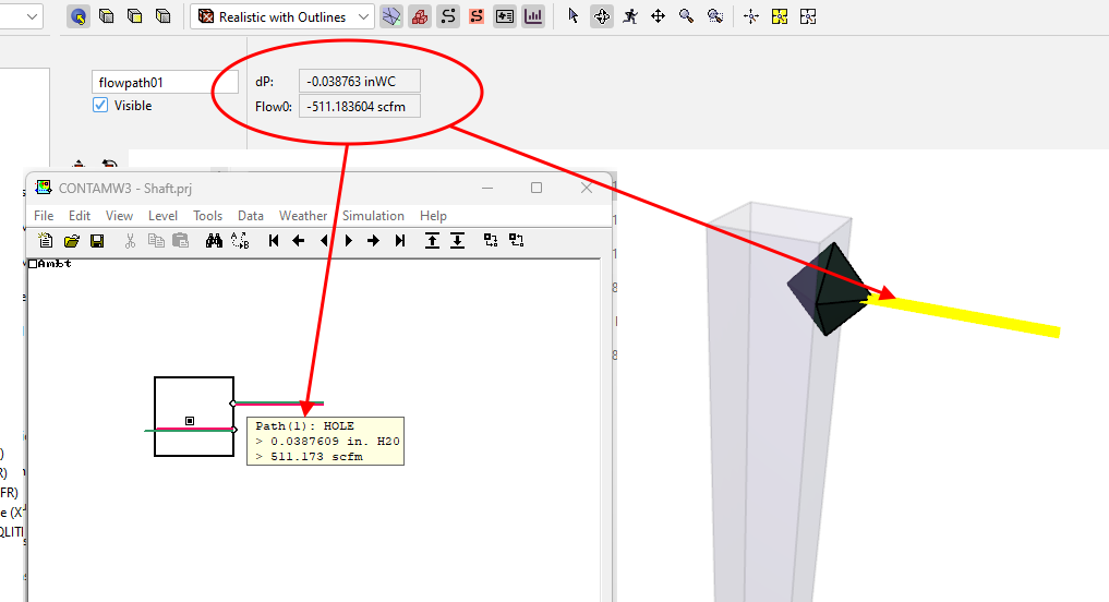
The results data can now be compared to the expectations of the ASHRAE stack effect problem and the results of an equivalent CONTAM simulation for verification. The ZIP file linked at the top of this document contains CONTAM PRJ input file to facilitate this work.
Related Tutorials
Second example from the ASHRAE Handbook of Smoke Control Engineering, Klote et al., 2012. Chapter 14 of the handbook, Network Modeling and CONTAM
This Feature Demo covers how to use the Performance Curve Flow Element
This Feature Demo details the steps to model door state changes in Ventus
(Legacy) Tutorial to experience the fundamental features of PyroSim
Video tutorial demonstrating the variables that may have an effect on evacuation time from aircraft cabins.
To demonstrate basic Ventus capabilities, we model a simple multi-story building for winter and summer conditions.
Tutorial demonstrating how to model jet fans in Pyrosim.
Tutorial demonstrating how to model a pressure relief vent in Pyrosim.