To follow along with this post, download the link: Getting Started Import 3D.zip.
Introduction
In this tutorial, we will demonstrate creating a Ventus model by importing 3D CAD models. Ventus can import a large number of CAD models, including IFC, IFCXML, DXF, DWG, and FBX file formats. We will demonstrate import of dwg and ifc models, but the approach is similar for all CAD formats.
We recommend that you work through the introductory examples before working on this problem.
Background - Working with Levels
Levels are the basic building blocks of a CONTAM model. The Z coordinate of a zone is defined by a reference to a level and then the relative height above that level. At this time, Ventus mimics the CONTAM approach.
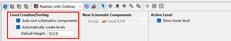
There are several controls.
- In the Property panel, the Default Height defines the distance between levels.
In the following examples, we will frequently say "At the top of the Navigation panel, in the Level list dropdown, select Add New."
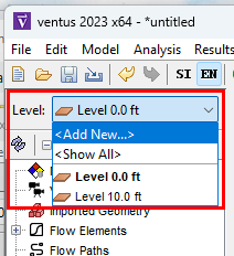
When this is done, the default behavior is to:
- Add a new level above highest existing level.
- The Z location of the level will be determined by the highest existing level and the Default Height.
- In this case, the highest existing level is 10.0 ft and with a Default Height of 10 ft, the new level will be created at 20.0 ft.
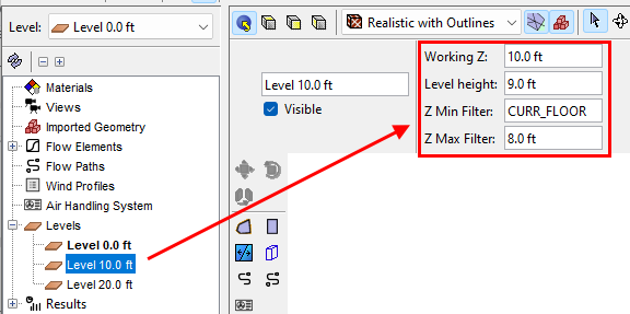
Once a level is created, there are several additional controls that are displayed when a level is selected.
- The Working Z is the coordinate at which new zones will be drawn.
- The Level Height is the height that will be used when calculating wall flow path areas.
- Z Min Filter is used for display purposes. Any geometry on level that is below the Z Min Filter will not be displayed. Usually this is left at the default CURR_FLOOR value.
- Z Max Filter is used for display purposes. Any geometry on level that is above the Z Max Filter will not be displayed. We will use this to clip ceilings so that we can easily draw zones.
- As displayed, there is a Level at 10 ft. Zones that are drawn will be at 10 ft and the wall leakage areas will use a wall height when calculating flow area. We will clip the top of this level.
Import DWG File and Save the Model
Use the Pathfinder-Fundamentals.dwg file from the downloaded pathfinder-fundamental.zip file.
To import the DWG file:
- In the File menu, click Import. Open the file Pathfinder-Fundamentals.dwg.
- In the Import dialog, click Next three times and then click Finish.
To save the Ventus model:
- In the File menu, click Save and save the Ventus model with the name import_dwg.
Make Some Changes to Improve Appearance
We will using EN units for this model:
To change the unit system:
- In the Main toolbar, select EN for US Customary units.
To change the display of the glass:
- Spin the model and click on a glass window.
- In the Property panel, click Material.
- Change the color to a light blue, change the opacity to 20%
- Click Advanced Materials.
- Change the Shininess to 50. Click OK to close the Advanced Materials dialog.
- Click OK to close the Material dialog.
- Save the model.
Determine the Model Level Locations
We want to set the correct Default Height and level locations for the model. To do this, we need to explore the model.
To change the viewing angle and identify Z bounds:
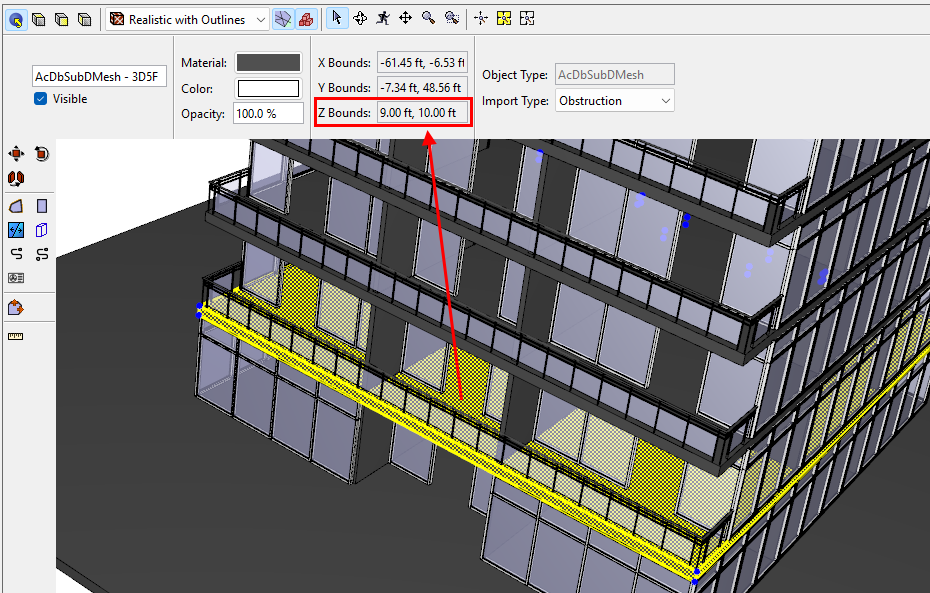
- Spin the model so that you can click on the different floors. As an alternate, you can Hide windows or ceilings to allow access for selecting.
- Click on the second level. As shown in the image, we see that the Z bounds are 9.0 ft and 10.0 ft. If we click the third level, the Z bounds are 19.0 ft and 20.0 ft.
- So we have found that the distance between levels is 10 ft and that the thickness of the floor is 1.0 ft.
When no object is selected, the Property Panel will display the Default Height.
To change the default height:
- In the Property panel, change the Default Height to 10.0 ft.
To add six additional levels:
- At the top of the Navigation panel, in the Level list dropdown, select Add New.
- Repeat six times until the top level is at 60.0 ft.
Starting at Level 0.0 and continuing to the top level, repeat the following steps to set the Z extents of the levels.
To change Level Height and Z Max (repeat six times):
- Set the Level Height to 9.0 ft. This will determine the wall height used to calculate wall flow areas.
- Set the Z Max Filter to 8.0 plus the Working Z. So for Level 0.0, this is 8. For Level 10.0, it will be 18, etc.
- Repeat for each level.
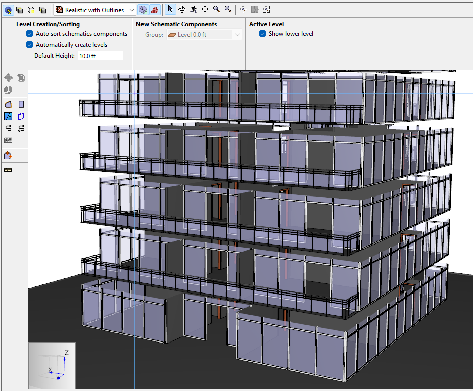
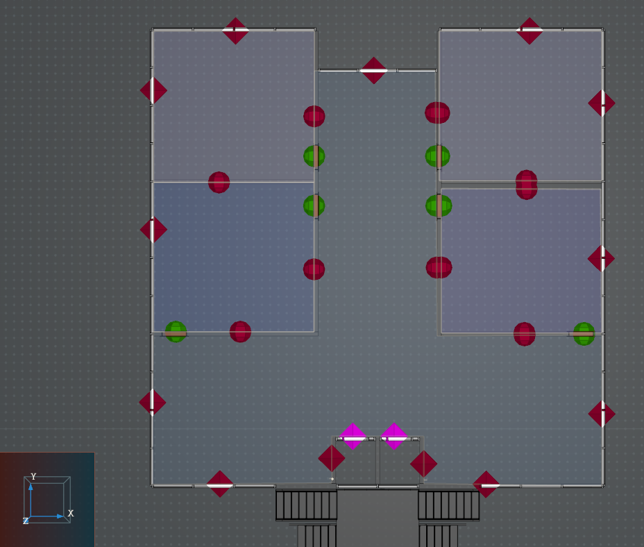
When finished, the model display is clipped.
Draw the Zones and Flow Paths
We can now draw the zones for each level.
To draw zones and flow paths for each level:
- Navigation panel, right-click Level 0.0 and select Set as Active Floor.
- In the View toolbar, select Top View and click Reset All.
- Now draw zones in the same manner you did in the earlier examples, using the Add a Rectangular Room and Add a Polygonal Room tools.
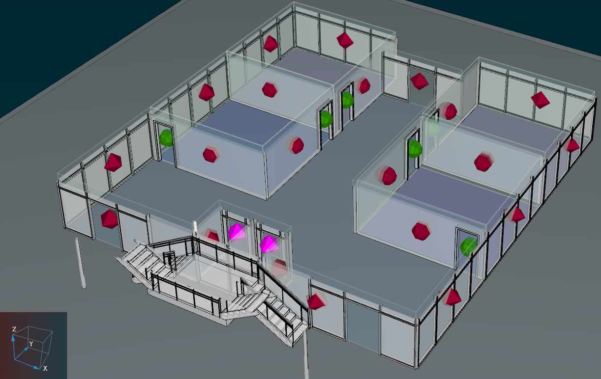
- Add flow paths as done in the previous examples.
- We can check the area of a wall flow path. As expected it corresponds to the length times the wall height of 9 ft.
Working with Gaps Between Zones
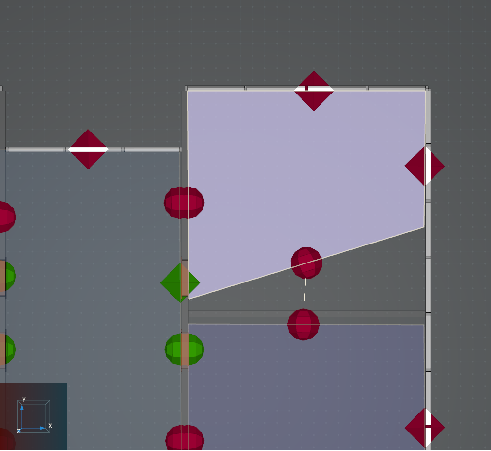
Due to the thickness of walls in the imported 3D file, there will be gaps of ambient volume between your zones. It is important to select the appropriate zone when creating flow paths with the tools in Ventus. You can accidentally link flow paths to gaps instead of zones, as in this extreme example:
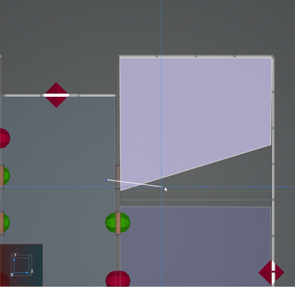
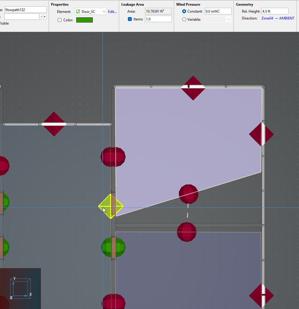
Although the line for the flow path passed through Zone10, the flow path links to ambient! The early warning of the flow path error is that it is a diamond body:
When you click on the flow path, you can see its details and confirm that there is a problem:
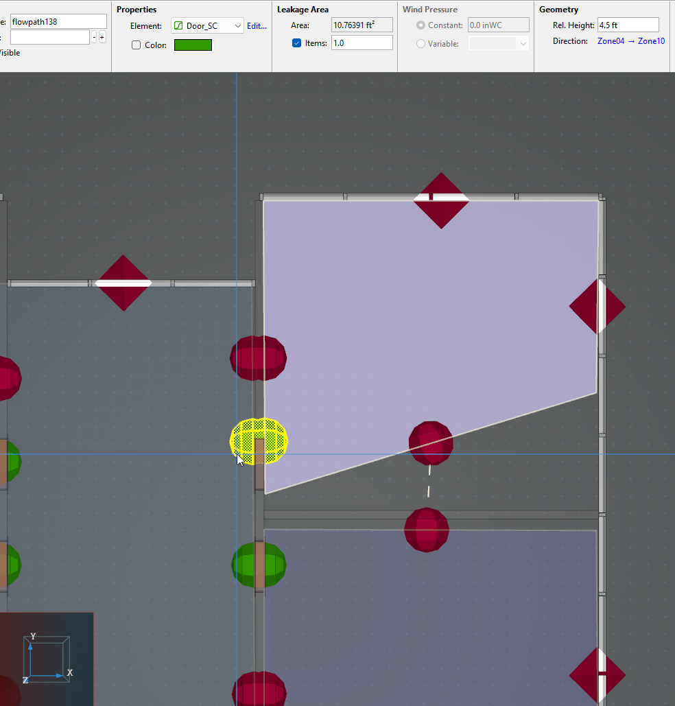
Delete the errant flow path and draw it properly, so that it links Zone04 and Zone10 as intented. The new flow path displays as a rounded body. You can verify the details by selecting it:
A note about angled zone walls
Internal flow paths will multiply by the wall area automatically. These internal flow paths always link two walls. When the wall angles differ by more than 1 degree, Ventus will provide a warning in the object tree. For more information, return to the basic tutorial "Import 3D DWG and IFC Models".
Finish the model with weather and wind data
Proceed to build the model on the remaining floors and run analysis, as desired.
Related Tutorials
(Legacy) Tutorial to experience the fundamental features of PyroSim
This video demonstrates creating a Ventus model by drawing on a 2D image.
Tutorial demonstrating how to model a fire in Pyrosim.
This tutorial teaches the user how to model basic Contaminants in Ventus.
This tutorial teaches the user how to a closed door Stairwell Pressurization study in Ventus.
This tutorial teaches the user how to an open door Stairwell Pressurization study in Ventus.
Video tutorial demonstrating how to fix geometry problems related to DWG importation.
In this tutorial we show how to fix three problems that can occur when BIM (Building Information Modeling) or CAD (Computer-Aided Design) models into Pathfinder.