Overview
This video demo demonstrates the creation of a Ventus model by drawing on a 2D image. Follow along with Engineer Daniel Swenson from Thunderhead Engineering as he presents a suitable workflow and provides context for key features.
Ventus provides features that speed up this process: scaled image placement, a Snap Grid, a merge Zones feature, and a Show Flow Path Input Geometry feature. This demo shows these capabilities within the context of smoke control analysis for a multi-story hotel atrium.
Ventus can import many types of 2D formats, including: BMP, GIF, JPG, JPEG, JIF, JPE, PNG, PDF, TIF, TGA, and TARGA. The procedure would be similar for all 2D formats.
Before Starting
- Review the Basic First Model tutorial.
- Read through the "Creating Geometry from Images" section of the Ventus User Manual
- Download the Drawing on a 2D Image zip folder to follow along.
Video Chapters
Each chapter provides written instructions.
0:00
Import the Floor plan at the desired scale
- Check that the unit setting is EN for English (US Customary) units.
- Import the floor plan
- In the Model menu, select New Background Image and choose the ground Floor WPI_Hotel_Ground_Floor.jpg file from the zip folder in Resources.
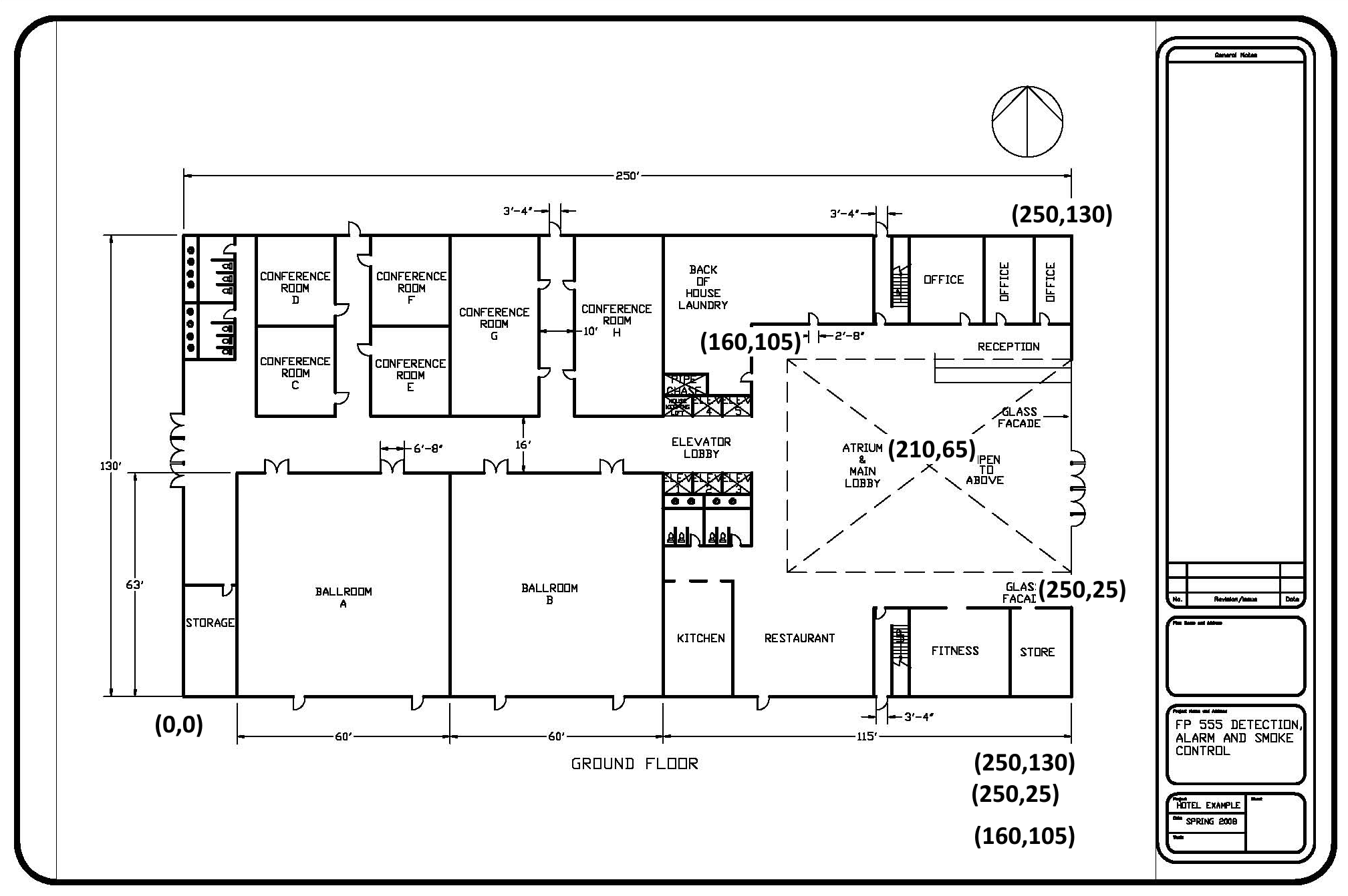
- Set an Anchor Point. In this model, we use the center of the atrium, with known coordinates (210,65,0) ft. For more information, see the Ventus User Manual.
- Set the scale using point A and point B, with known dimension 250 ft.
- Select OK.
- Switch to Top View.
3:46
Work with Snap Grid ON to ensure precision
- Set the Snap Grid spacing to 5 ft.
- Draw the boundary of the Floor plate with the Snap Grid on.
- Draw the boundary of the atrium with the Snap Grid on.
- Change the Opacity of both Zones to 20 %.
4:18
Draw the rest of the ground Floor Zones
Since the building must be analyzed for the atrium, individual conference Rooms can be Zoned in groups to save time. We are not concerned with the individual temperatures inside these Rooms for an atrium smoke control study. For example, Conference Room C and Conference Room D will be considered one Zone in the Ventus model.
The remainder of the Zones may be drawn with Snap Grid off. If more precision is needed, the user can edit the Snap Grid to support each Zone dimension. For example, it may be helpful to use a Snap Grid of 1 ft when drawing the hallway with a 16 ft width.
You may also find the Add a Thin Wall drawing tool helpful to define Zones on the ground Floor. With this tool, you can split Zones quickly as shown in the Ventus User Manual.
9:15
Merging the lobby and atrium Zone
- Select all relevant Zones by holding the CTRL key.
- Right-Click on any selected Zone and choose Merge Rooms to merge them into one continuous Zone.
- Change the color to quickly identify the entire composite Zone.
10:30
Setting Stair Zone temperatures
- Change the Zone temperature setting for both Stairwells from the default value 73 °F to the Stair winter value, 8 °F. (Dr. Swenson uses 13 °F, but he will correct it to 8 °F at 23:20 of this tutorial)
12:00
Adding appropriate Flow Paths to the ground Floor
Add Flow Elements for Walls, doors, and shafts. The leakages are defined by flow areas and flow coefficients used for the ASHRAE Handbook of Smoke Control Example 14.3, featured in Ventus Validation #3. The Flow Elements are included as a VLIB file in the zip folder (Before Starting) and also presented in Table 1 as part of the Resources section of this tutorial.
For information on importing Flow Elements from a Ventus Library, see Ventus User Manual: Object Libraries
13:15
Checking that the model is defined with each Flow Path specified
Work through the model by identifying each Zone and verifying surrounding Flow Paths.
15:23
Checking Flow Path area calculation values of certain Zones
- Select a Flow Path in the view window to view the calculated values, which will be run with the ContamX solver.
- The user can manually input the "true value" of each Flow Path area Multiplier if needed.
17:20
Using the Move/Copy tool to copy Zones to the second level
- Copy relevant Zones to a new level with a height of 10 ft. Dr. Swenson does not recommend copying Flow Paths; many will change definition on the second level, and they are quick to draw in Ventus.
19:00
Importing the typical Floor plan and adding horizontal Flow Paths
- With
Level 2set as the active level, create a new background image scaled to the model.- Choose the typical Floor plan, WPI_Hotel_Typical_Floor_Plan.jpg file.
- Follow steps as before to place and scale the image with the Anchor Point at (210,65,10) ft.
- Use the bottom line of the Floor plan (SW corner to SE corner) to set the Distance A to B at 115 ft.
- Add appropriate horizontal Flow Paths and edit Zones on the second level to reflect changes in the geometry
21:49
Creating the vertical Flow Paths
- With the second level active, create vertical Flow Paths to the Zones below. These Flow Paths describe leakages through the Floors for the Hotel sections and airflow through the Elevator shaft, pipe shaft, and Stairwell.
- In the object tree, hide the background image(s).
The second level is almost complete; you must now add the vertical atrium Flow Path.
23:20
Making the vertical atrium Flow Path
Ventus does not implement phantom Zones as used in ContamW.
Our model will be 30 levels total; there will be stack effect and temperature variation in the atrium, so you should define discrete Zones for each level of the atrium.
- Define Zones as if they are vertically aligned separate Rooms.
- Create an appropriate Flow Path and establish a large flow area between each atrium Zone to simulate the airflow.
Reuse the Elev Flow Element with a multiplier
- Add an Elev Flow Path between level 2 and level 1.
- Apply the appropriate multiplier to model airflow in the atrium between levels. For this very large opening, an appropriate multiplier is 10 for 10 times the area of the pipe shaft.
The second level is now ready to be copied as the "typical level" of the multi-story hotel building.
29:00
Using the Copy/Move tool to copy 28 levels above Level 2
- In the Level Creation/Sorting part of the Properties panel, ensure that Ventus is set to Auto sort schematics components and to Automatically create levels with a default height of 3 m.
- With the second level set as the active level
- Select all items in the 3D graphics window.
- Select Copy/Move Objects.
- Select Copy Mode and enter in 28 Copies.
- Enter 10 ft for the Move Z: value.
- Select Copy/Move to create all 28 levels in one step!
The model is ready to be run. This simulation will be done with the weather conditions in Table 3.
31:20
Running the model and viewing results
After running the simulation, results are displayed in the view window.
- Individual Flow Path results can be inspected in the view window by selecting the result vectors for details
- You can search and isolate key results in the results window (Path Data and Zone Data)
Using the Modify Vertex feature
To modify a Zone Vertex
- Left-click on a Zone you want to modify.
- Left-click on the Vertex of the Zone that you want to move.
- Move the cursor in any direction
- Press TAB three times to obtain the dialogue box.
- Manually enter the absolute position of the Vertex.
- Press ENTER.
- Press ESC.
Compare to Figure 1.
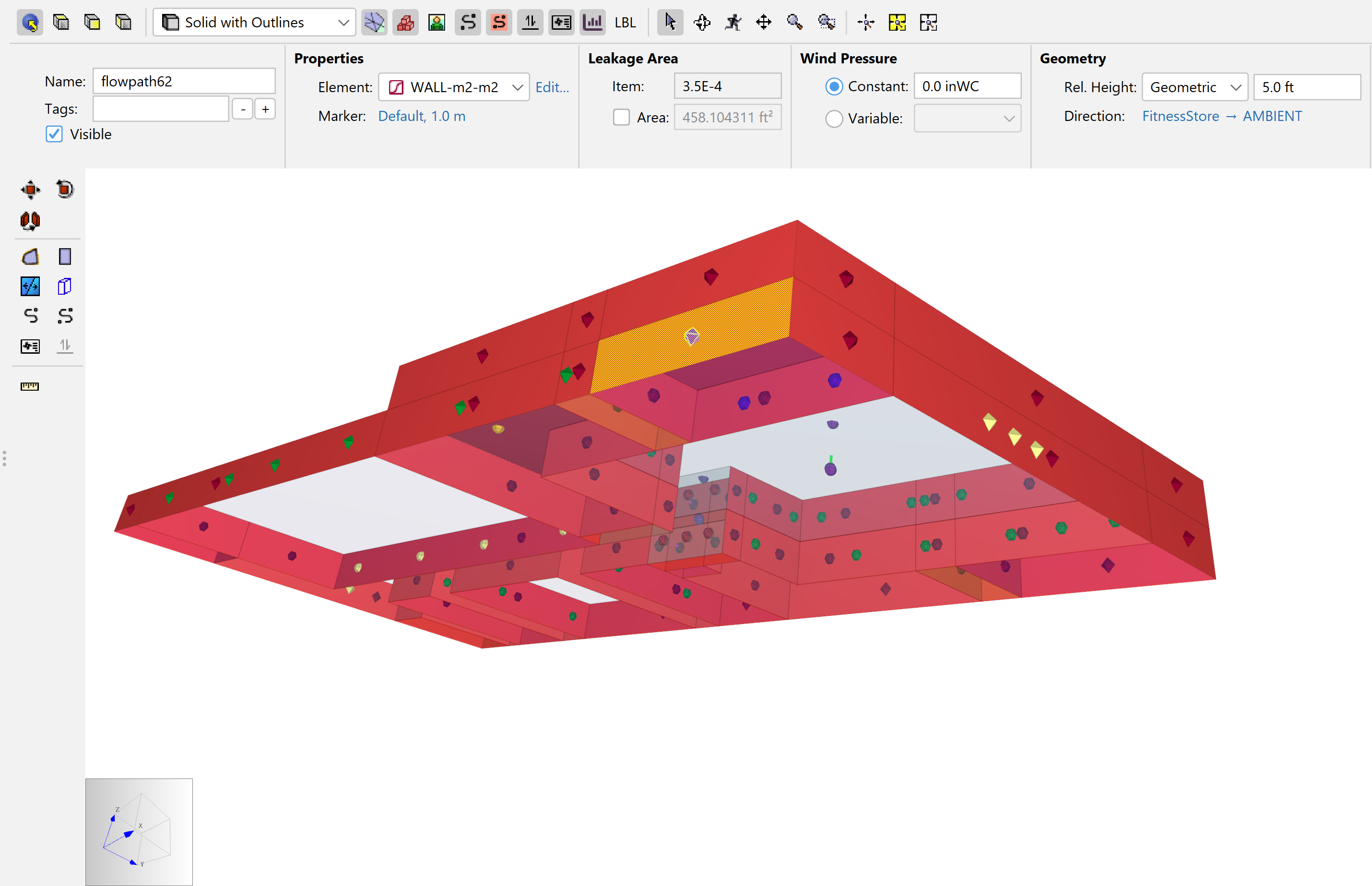
Using the Show Flow Path Input Geometry feature
To investigate Flow Path Input Geometry
- In the View toolbar, select
 Show Flow Path Input Geometry.
 - All Zone areas that have associated area or length Flow Path per-area or per-length calculations will be highlighted in red. Zone areas that do NOT have leakage Flow Path definition will be left as their default color, making them easier to find.
- Additionally, when a Flow Path is selected, the tool will identify the area or length used in that Flow Path calculation with a yellow mesh applied as well as the red highlight. For example, in Figure 2 the area used for Flow Path62 is identified.
Resources
Our model will be made using two Floor plans. The ground Floor plan and the Floor plan for levels 2-30 are shown in Figure 3 and Figure 4 respectively. Note that Figure 3 includes some key coordinates for importing and creating the model.

| Path Description | Element Name | Marker Color | Flow Area (m²) |
|---|---|---|---|
| Single door (closed) | Door-SC | Green | 0.0158 |
| Double door (closed) | Door-DC | Yellow | 0.0316 |
| Wall per m² | Wall-m2-m2 | Maroon | 3.50E-04 |
| Floor per m² | Floor-m2-m2 | Gold | 1.70E-04 |
| Elevator Door (closed) | Door-Elev | Dark purple | 0.055742 (0.6 ft2) |
| Elevator Shaft | Elev | Orange | See Table 2. |
| Stair | Stair | Blue | See Table 2. |
| MEP Shaft | Pipe | Light Purple | See Table 2. |
| Element Name | height Level | Area | Perimeter | Roughness | Density | stair design |
|---|---|---|---|---|---|---|
| Elev | 10ft | 150 ft2 | 62 ft | 0.3281 | ||
| Stair | 10ft | 250 ft2 | 0 pers/ft2 | Closed | ||
| Pipe | 10ft | 75 ft2 | 37 ft | 0.3281 |
| Location | Temperature (°F) |
|---|---|
| Outdoor | -4 |
| Building | 73 |
| Stairwell | 8 |
Conclusion
To download the most recent version of Ventus, please visit the Ventus Download page. Please contact support@thunderheadeng.com with any questions or feedback regarding our products or documentation.
Acknowledgements
We thank WPI for sharing this example, a building that was used for homework in their evacuation class. The temperature conditions and Flow Path values in Table 1 and Table 3 are set using the table in the ASHRAE Handbook of Smoke Control Engineering, Example 14.3. References for technical knowledge in this article are limited to sources in the Ventus user manual Bibliography.
Related Tutorials
This Feature Demo details the steps to create a Ventus model with imported 3D geometry.
How to simplify post-processing data collection with seasonal scenarios and scheduled stairwell temperatures.
This Feature Demo details the steps to model basic Contaminants in Ventus.
This tutorial teaches the user how to perform a closed door Stairwell Pressurization study in Ventus.
This tutorial teaches the user how to perform an open door Stairwell Pressurization study in Ventus.
Video tutorial demonstrating the difference in evacuation times when occupant flow is properly balanced.
Tutorial demonstrating how to model critical velocity in Pyrosim using the example of a tunnel fire.
Video tutorial demonstarting how to assign exit goals to percentages of the occupant population.