Overview
This tutorial will demonstrate how to model wind and other atmospheric conditions using PyroSim’s Wind Parameters and Reserved Surfaces. In the 2021.3 release of PyroSim, we added support for some new FDS features that make modeling these different wind conditions simpler. This tutorial will cover how to use these new features. Users will learn how to configure a simple initial wind, modify the speed and direction of the wind over time, and control wind development at the boundaries of a model.
Before Starting
Before beginning this tutorial:
- Download the Simple Wind in PyroSim models to follow along. (These models are modified versions of the wind_example_32.fds verification model provided by NIST.)
- Read through the User Manual sections on Wind Parameters and Reserved Surfaces.
Introduction
It is possible to model and observe fire simulation effects due to wind and atmospheric conditions with PyroSim and FDS. FDS provides tools to model these conditions with a range of complexity.
At the most basic level, a simple initial wind condition can be modeled by defining a direction and windspeed. Adding more complexity to the condition, the user can define an initial wind field that varies direction and windspeed over time. With yet more complexity, the user can define this varying wind field to also vary over altitude. Finally, the user can also model wind conditions entirely differently, utlilizing the Monin-Obukhov Similarity theory. While the latter two methods are more accurate, this tutorial is intended only to provide a simple understanding of wind simulation in PyroSim. It will provide an example of the first two cases listed above. To learn about the Monin-Obukhov Similarity or simulating wind in general, check out Section 18.1 of the FDS User Guide.
The files provided above model a large 500mx500mx200m area with a number of large obstructions representing buildings and large obstructions like shipping containers. One of the buildings is configured as a 50,000kW ultra-fast t^2 growth fire using an Oak Wood Reaction. The simulation runs for a total of 600 seconds.
Defining a Simple Initial Wind
The goal of this section is to get the user familiar with the different model attributes that are required to effectively model atmospheric wind in PyroSim. In this section, the user will learn how to set up a model for wind, how to define a simple wind, and how to view the results of a wind simulation in the Results viewer. After going through this section, the user should be able to set up a simple wind simulation in any model made in PyroSim.
Setting up the model
To begin, open the Simple Wind in PyroSim model, available for download in Before Starting.
This model already has the geometry, fire, and Results slices defined.
The mesh of this model is entirely closed meaning no ambient air, or wind flow, can enter the domain of the model.
To open the boundaries of the mesh:
- Right-Click
Mesh01in the Navigation view. - Click
Open Mesh boundariesin the context menu.
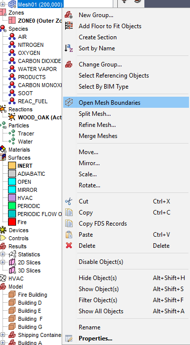
Mesh01This will create vents at all of the external boundaries of the mesh, group them by mesh, and place all of the grouped vents in a larger Mesh Boundary Vents group in the Navigation view.
Notice that at the internal boundaries, where two meshes abutt, no vents were created.
All of these vents are created with the OPEN boundary condition, however we do not want this condition for all of the vents.
For each vent appended with [ZMIN]:
- Double-Click the mesh in the Navigation view to open the
Vent Propertiesdialog. - In the dialog, set the
SurfacetoINERT
This will prevent air from moving through these vents and will represent the ground in our model.
Leave the other vents with the OPEN surface.
These will represent a ambient atmospheric boundaries with no special development properties associated with them.
Defining the Initial Wind
To being configuring wind in the model:
- Open the
Simulation Parametersdialog underAnalysis > Simulation Parameters - Click the
Environmenttab. - In the
Environmenttab, click the checkbox next toConfigure Wind, then clickEdit.
This will open the Wind Parameters dialog.
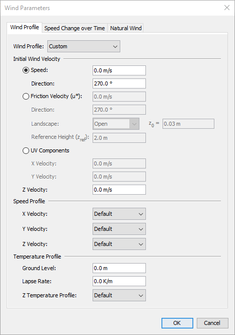
To configure a simple wind in the Wind Parameters dialog:
- Change the
Speedvalue to5.0m/s - Change the
Directionvalue to0°.
- Click
Okin theWind ParametersandSimulation Parametersdialogs.
These settings will simulate a 5.0m/s wind coming out of the North of the model.
Note that these are the initial values for the wind.
FDS will create an initial velocity field using these values everywhere in the model.
The wind will be affected by obstructions and flows generated by the model.
Run the model by clicking the ![]()
Run FDS icon.
Viewing the Results
With the simulation complete, open the results in the Results viewer by clicking Show Results in the Run FDS dialog, or by clicking ![]()
Show Results.
In the Results viewer:
- Open the
2D Slices > Velocitydropdown. - In the
Velocitydropdown, double-click all of theZ = 10.000slices to show them in the 3D window. - Click the
Playbutton at the bottom of the window.
The Velocity slice contour should show that a wind coming out of the North of the model with a 5.0m/s speed.
It should also show that as the wind interacts with the obstructions in the model, it develops areas of stagnation and drag immediately in front of and behind the obstructions.
Wind also has an effect on the flow of smoke and other reaction products in the model. To view this:
- Double-click
2D Slicesin the Navigation View to hide all of the shown slices. - Double-click
3D Smokein the Navigation view to show the reaction products in the 3D window. - Click

Side View.
This viewing angle has the North direction to the left. The 3D smoke products should show the wind coming out of the North, causing the smoke and other products from the burning obstruction to travel to the South.
130s to 180sThe user should now be able to set up simulations using simple winds.
Changing Wind Speed and Direction over Time
This section adds an additional layer of complexity to wind definition. The goal of this section is to define a wind configuration that changes speed and direction over time. The user will accomplish this by defining both a Speed and Direction ramp for the wind. By the end of this section, the user should be familiar with how to define these profiles, as well as what effects they have on a simulation.
Configuring the Speed Profile
To begin, close the Results viewer and move back to the main PyroSim window. In the main window:
- Re-open the
Wind Parametersdialog. - Click on the
Speed Change over Timetab. - In the
Speeddropdown, selectCustom. - Click
Edit Values.
The Ramping Function Values dialog should now be visible.
This dialog allows definition of a profile for the speed of the wind over time.
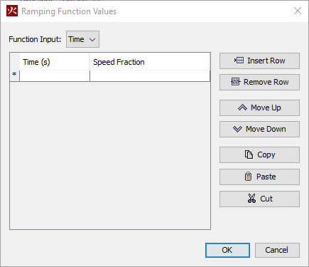
Ramping Function Values dialog.Each row in the table of this dialog represents a point in the speed profile.
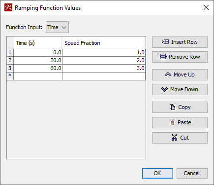
The left-hand column defines the time, and the right-hand column represents the speed at the given time, as a fraction of the speed defined in the Wind Profile tab.
Define a simple speed profile by copying the speed profile given below, then clicking Ok.
Configuring the Direction Profile
Defining the Direction profile is similar to defining the Speed profile. To define the Direction profile:
- In the
Directiondropdown, selectCustom. - Click
Edit Values.
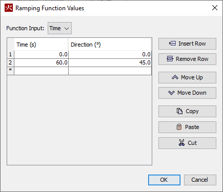
The Ramping Function Values dialog should now be visible, similar to Figure 6.
The only difference between the dialogs is that instead of mapping the speed, this dialog maps the Direction of the wind in degrees.
Define a simple Direction profile by copying the Direction profile given below, then clicking Ok.
After clicking Ok, close out of the Wind Parameters and Simulation Parameters profiles by also clicking Ok.
Run the model by clicking the ![]()
Run FDS icon.
Viewing Results
With the simulation complete, open the results in the Results viewer by clicking Show Results in the Run FDS dialog, or by clicking ![]()
Show Results.
In the Results viewer:
- Open the
2D Slice Vectors > VELOCITYdropdown. - Double-click on the
Z = 10.000items to display them in the 3D window. - In the bottom left corner of the screen, set the
Vector Magnitudeto 2500 to make the vectors more visible. - Click the play button to view the results.

The Velocity vectors, shown in Figure 8, should show the wind intitially starting at 5.0m/s out of the North of the model, increasing speed to 10.0m/s by 30s, 15.0m/s by 60s, and then the wind shifting direction to flow out of the North East by 60s.
The smoke output of the fire is also affected by the shift in speed and direction. Figure 9 showcases this. The smoke initially flows to the South, but after the wind shifts to come out of the North East, the smoke also shifts to flow to the South West.
The user should now be able to modify wind flow in models to vary speed and direction over time.
Boundary conditions and reserved surfaces
This section covers modifying the boundary conditions of a model. The user will learn how to change the boundary conditions, and will also learn which conditions are available and what effects each condition will have on a model. The user will accomplish this by applying each condition to the existing model and observing their effects. Note that these conditions are best used in models that use the Monin-Obukhov Similarity theory to govern their wind flow. Modeling using this theory will be covered in it’s own dedicated tutorial. This section aims to get the user familiar with the basic effects of these boundary conditions.
The Open Condition
The OPEN condition is the condition that has been used throughout this tutorial.
It is applied by applying the OPEN surface to the boundary vents.
This condition simulates a passive opening to ambient conditions and is the most basic of the boundary conditions.
The Periodic Condition
The PERIODIC condition allows the model to develop wind more naturally over time.
This condition allows simulation of an infinitely large domain for the flows in a model.
It does this by taking any flows that exit a PERIODIC vent and injecting them back in to a PERIODIC vent that is on the exact opposite side of the domain from the exit vent.
To apply the PERIODIC condition to this model:
- In the main PyroSim window, select all of the vents appended with
XMIN,XMAX,YMIN, andYMAXby holding down theCtrlkey and clicking each of them. - Continuing to hold the
Ctrlkey, double click on of the vents to open theVent Propertiesdialog. - Change the
SurfacefromOPENtoPERIODIC.
Now run the model with the new PERIODIC boundary conditions by clicking the ![]()
Run FDS icon.
With the simulation complete, open the results in the Results viewer by clicking Show Results in the Run FDS dialog, or by clicking ![]()
Show Results.
Notice that even though only the boundary condition was changed in the model, the results are drastically different. For one, the effects of the wind flow exiting the model to the South are wrapped back around to enter the North boundary of the model, as shown in Figure 10. These effects then develop differently over time as they encounter the model, exit to the South again with a different flow pattern than they entered with, and then re-enter on the Northern boundary to continue the cycle. Secondly, the smoke and other reaction products exit the model to the South and re-enter the Northern boundary just as the wind does, as shown in Figure 11. This may not be desirable for some models and is addressed by the next boundary condition.
PERIODIC boundary condition.
PERIODIC boundary condition.Finally, notice that even though that neither the Speed nor Direction profiles were changed, the wind flow no longer changes direction.
This is because FDS only enforces these profiles at the boundaries where they enter.
Because PERIODIC boundary condition was used, the changes made by these profiles are overridden by the condition of the wind as it exited a PERIODIC surface.
This is why this condition is best used in a Monin-Obukhov Similarity theory model - if a set of profiles are defined, like in Changing Wind Speed and Direction over Time, the PERIODIC surface will override it.
The Periodic Flow Only Condition
The PERIODIC FLOW ONLY condition behaves similarly to the PERIODIC surface, in that the effects of the wind flow wrap back around to the other side of the domain after they exit.
However unlike the PERIODIC surface, smoke and other reaction products do not wrap around the domain, shown in Figure 12.
They instead exit the model like the OPEN condition.
In prior versions of FDS, this was accomplished by applying the PERIODIC boundary condition and then using the WIND=.true parameter.
This was deprecated in FDS 6.7.5 and the PERIODIC FLOW ONLY surface was added.
PERIODIC FLOW ONLY boundary condition.Conclusion
Users should now be familiar with how to configure simple initial winds, modify the direction and speed of those winds over time, and should understand the different FDS reserve surfaces provided through PyroSim and what their effects on will be on a model.
To download the most recent version of PyroSim, please visit the PyroSim support page and click the link for the current release. Please contact support@thunderheadeng.com with any questions or feedback regarding our products or documentation.
Related Tutorials
Tutorial demonstrating how to model a pressure relief vent in Pyrosim.
Tutorial demonstrating how to use PyroSim/FDS to Maximize Solar Panel Convective Cooling.
Tutorial demonstrating how to create and FDS Velocity Patch in Pyrosim.
This tutorial teaches the user how to model door state changes in Ventus
(Legacy) Tutorial to experience the fundamental features of PyroSim
Video tutorial demonstrating the variables that may have an effect on evacuation time from aircraft cabins.
To demonstrate basic Ventus capabilities, we will model a simple six-story building for winter and summer conditions.
Video tutorial demonstarting how to assign exit goals to percentages of the occupant population.