Introduction
Every solid surface in an FDS model defines convective and radiative thermal flux boundary conditions. What may not be immediately obvious is that each of the terms are always being calculated, sometimes using default parameters that may not have been explicitly specified by the user. The reason we mention this is that we will likely redesign the PyroSim user interface to more clearly help the user understand what options are being selected when they create a surface.
The convective heat transfer flux is given by:
where the default convective heat transfer coefficient \(h\) is based on a combination of natural and forced convection correlations, \(T_{g}\) is the gas temperature, and \(T_{w}\) is the wall temperature. Normally a user will not modify the convective heat transfer model \(h\), but the user is responsible for how \(T_{w}\) will be calculated, either as a fixed temperature or as part of thermal conduction into a solid.
The thermal radiation flux is conceptually more complicated. If it is assumed that the thermal radiation from the surrounding gases is absorbed within an infinitely thin layer at the surface of the solid obstruction, then the net radiative heat flux is the sum of incoming and outgoing components:
with the incoming radiation a function of radiation intensity and geometry and the outgoing radiation given by:
where \(\epsilon\) is the emissivity, \(\sigma\) is the Stefan-Boltzmann constant, and the wall temperature is raised to the fourth power. The user will typically only specify the emissivity and is again responsible for how the wall temperature will be calculated.
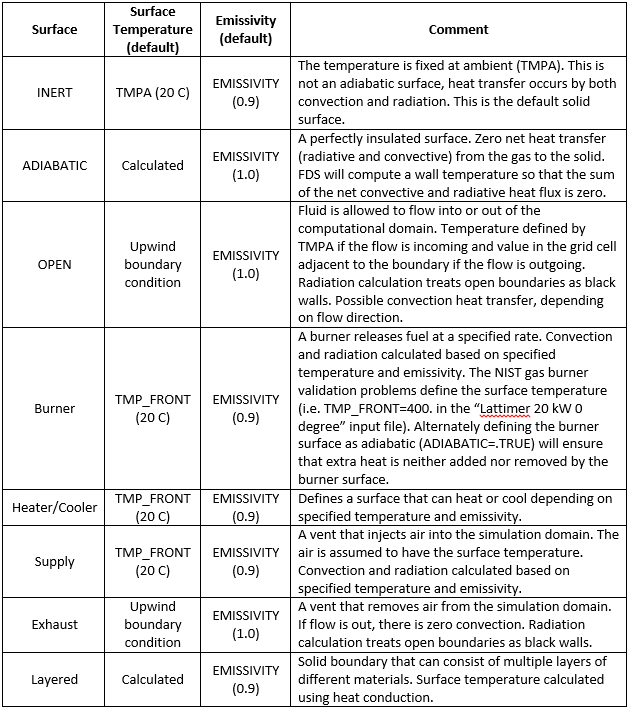
FDS provides some default surfaces (INERT, ADIABATIC, and OPEN) and PyroSim tries to help the user by further categorizing surface types (Burner, Heater/Cooler, Supply, Exhaust, and Layered). How each surface handles convection and radiation heat transfer is summarized in Figure 1 below.
Example
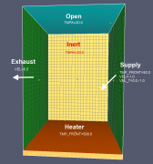
Here is an example that exercises most of the above options.
There is a supply inlet on the right with a temperature of 50.0 C.
On the bottom, a heater at 500 C supplies heat by convection and radiation.
On the left, some of the air is exhausted with the surface temperature value of 20 C.
The top is OPEN and the front and back sides are INERT.
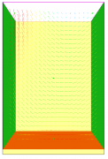
The velocity vectors are shown in Figure 3.
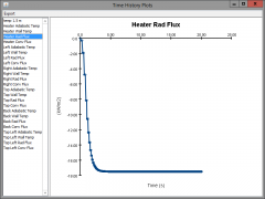
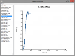
The calculated heat fluxes are consistent with the above discussion, with both convective and radiative components on all surfaces. Figure 4 shows the radiative flux for the heater (radiating into the enclosure) and Figure 5 shows the radiative flux for the exhaust (the radiation removes heat from the enclosure).
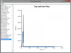
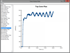
At the top OPEN surface we see that on the left side (where the flow is out of the model) the convective heat flux is zero, as shown in Figure 6, while on the right (where the flow is mostly tangent to the surface) the convective heat flux is significant, as shown in Figure 7.
Summary
In summary, the user needs to be aware that even if they do not explicitly define convection or radiation parameters, these fluxes will still be calculated for all surfaces using the default values. For more detailed discussion, see the FDS User Guide and the FDS Technical Reference Guide.
Here is a listing of the FDS input file used in the example. PyroSim users: copy the text and save as a *.fds file. Then, on the File menu click Import FDS/CAD file… and select the file. This is an FDS 6 input file.
supply_tmpa20_heat500.fds
Generated by PyroSim - Version 2014.1.0331
Apr 23, 2014 3:56:40 PM

&HEAD CHID='supply_tmpa20_heat500'/
&TIME T_END=20.0/
&DUMP RENDER_FILE='supply_tmpa20_heat500.ge1'/
&MISC BAROCLINIC=.FALSE./

&MESH ID='MESH', IJK=20,20,30, XB=-1.0,1.0,-1.0,1.0,0.0,3.0/

&REAC ID='POLYURETHANE_REAC',
      FYI='SFPE Handbook, GM27',
      FUEL='REAC_FUEL',
      C=1.0,
      H=1.7,
      O=0.3,
      N=0.08,
      CO_YIELD=0.042,
      SOOT_YIELD=0.198/

&DEVC ID='temp 1.5 m', QUANTITY='TEMPERATURE', XYZ=0.0,0.0,1.5/
&DEVC ID='Heater Adiabatic Temp', QUANTITY='ADIABATIC SURFACE TEMPERATURE', XYZ=0.0,0.0,0.1, IOR=3/
&DEVC ID='Heater Wall Temp', QUANTITY='WALL TEMPERATURE', XYZ=0.0,0.0,0.1, IOR=3/
&DEVC ID='Heater Rad Flux', QUANTITY='RADIATIVE HEAT FLUX', XYZ=0.0,0.0,0.1, IOR=3/
&DEVC ID='Heater Conv Flux', QUANTITY='CONVECTIVE HEAT FLUX', XYZ=0.0,0.0,0.1, IOR=3/
&DEVC ID='Left Adiabatic Temp', QUANTITY='ADIABATIC SURFACE TEMPERATURE', XYZ=-1.0,0.0,1.5, IOR=1/
&DEVC ID='Left Wall Temp', QUANTITY='WALL TEMPERATURE', XYZ=-1.0,0.0,1.5, IOR=1/
&DEVC ID='Left Rad Flux', QUANTITY='RADIATIVE HEAT FLUX', XYZ=-1.0,0.0,1.5, IOR=1/
&DEVC ID='Left Conv Flux', QUANTITY='CONVECTIVE HEAT FLUX', XYZ=-1.0,0.0,1.5, IOR=1/
&DEVC ID='Right Adiabatic Temp', QUANTITY='ADIABATIC SURFACE TEMPERATURE', XYZ=1.0,0.0,1.5, IOR=-1/
&DEVC ID='Right Wall Temp', QUANTITY='WALL TEMPERATURE', XYZ=1.0,0.0,1.5, IOR=-1/
&DEVC ID='Right Rad Flux', QUANTITY='RADIATIVE HEAT FLUX', XYZ=1.0,0.0,1.5, IOR=-1/
&DEVC ID='Right Conv Flux', QUANTITY='CONVECTIVE HEAT FLUX', XYZ=1.0,0.0,1.5, IOR=-1/
&DEVC ID='Top Adiabatic Temp', QUANTITY='ADIABATIC SURFACE TEMPERATURE', XYZ=0.9,0.0,3.0, IOR=-3/
&DEVC ID='Top Wall Temp', QUANTITY='WALL TEMPERATURE', XYZ=0.9,0.0,3.0, IOR=-3/
&DEVC ID='Top Rad Flux', QUANTITY='RADIATIVE HEAT FLUX', XYZ=0.9,0.0,3.0, IOR=-3/
&DEVC ID='Top Conv Flux', QUANTITY='CONVECTIVE HEAT FLUX', XYZ=0.9,0.0,3.0, IOR=-3/
&DEVC ID='Back Adiabatic Temp', QUANTITY='ADIABATIC SURFACE TEMPERATURE', XYZ=0.0,1.0,1.5, IOR=-2/
&DEVC ID='Back Wall Temp', QUANTITY='WALL TEMPERATURE', XYZ=0.0,1.0,1.5, IOR=-2/
&DEVC ID='Back Rad Flux', QUANTITY='RADIATIVE HEAT FLUX', XYZ=0.0,1.0,1.5, IOR=-2/
&DEVC ID='Back Conv Flux', QUANTITY='CONVECTIVE HEAT FLUX', XYZ=0.0,1.0,1.5, IOR=-2/
&DEVC ID='Top Left Adiabatic Temp', QUANTITY='ADIABATIC SURFACE TEMPERATURE', XYZ=-0.9,0.0,3.0, IOR=-3/
&DEVC ID='Top Left Wall Temp', QUANTITY='WALL TEMPERATURE', XYZ=-0.9,0.0,3.0, IOR=-3/
&DEVC ID='Top Left Rad Flux', QUANTITY='RADIATIVE HEAT FLUX', XYZ=-0.9,0.0,3.0, IOR=-3/
&DEVC ID='Top Left Conv Flux', QUANTITY='CONVECTIVE HEAT FLUX', XYZ=-0.9,0.0,3.0, IOR=-3/
&SURF ID='Supply',
      RGB=26,204,26,
      TMP_FRONT=50.0,
      VEL=-1.0,
      VEL_T=0.0,-1.0/
&SURF ID='Heater',
      RGB=255,102,0,
      TMP_FRONT=500.0/
&SURF ID='Exhaust',
      RGB=26,204,26,
      VEL=0.5/

&OBST XB=-1.0,1.0,-1.0,1.0,0.0,0.1, SURF_IDS='Heater','INERT','INERT'/ Base

&VENT SURF_ID='Supply', XB=1.0,1.0,-1.0,1.0,0.0,3.0/ Supply
&VENT SURF_ID='OPEN', XB=-1.0,1.0,-1.0,1.0,3.0,3.0/ Exhaust
&VENT SURF_ID='Exhaust', XB=-1.0,-1.0,-1.0,1.0,0.0,3.0/ Near zero supply

&BNDF QUANTITY='ADIABATIC SURFACE TEMPERATURE'/
&BNDF QUANTITY='WALL TEMPERATURE'/

&SLCF QUANTITY='TEMPERATURE', PBY=0.0/
&SLCF QUANTITY='VELOCITY', VECTOR=.TRUE., PBY=0.0/

&TAIL /
To download the most recent version of PyroSim, please visit the the PyroSim Support page and click the link for the current release. If you have any questions, please contact support@thunderheadeng.com.
Related Tutorials
Tutorial demonstrating how to use PyroSim/FDS to Maximize Solar Panel Convective Cooling.
(Legacy) Tutorial to experience the fundamental features of PyroSim
Tutorial demonstrating how to model Heat Conduction in Pyrosim.
Tutorial demonstrating how to create and FDS Velocity Patch in Pyrosim.
Tutorial demonstrating how to model jet fans in Pyrosim.
Tutorial demonstrating how to model Smoke Visibility and Obscuration in Pyrosim.
Tutorial demonstrating how to model critical velocity in Pyrosim using the example of a tunnel fire.
Tutorial to experience the fundamental features of Pathfinder