Introduction
Let us solve the problem of a pressure relief vent where air is injected into a room, the pressure in the room is monitored, and a vent is opened when a set pressure is reached. This model requires some extra steps that might not be obvious. The key is to include at least two pressure zones in your model. This tutorial will guide you through the steps required to model this type of vent.
Modeling a Pressure Relief Vent
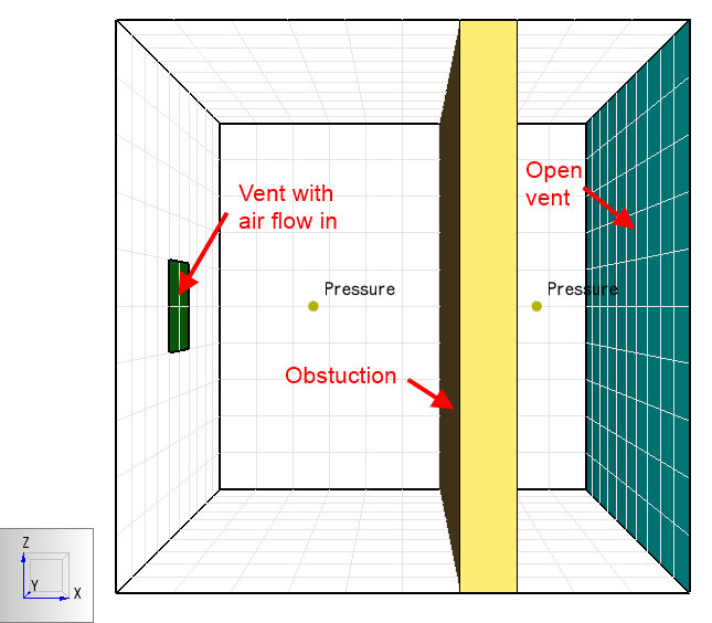
First we look at Figure 1, a model that is not correct.
Our model is a 10 m cube room, with an obstruction that completely separates the room into two compartments.
The compartment on the left has an inlet vent and the one on the right has a vent that is open to the atmosphere.
There are two pressure monitors and the default boundary surfaces are INERT.
You likely expect that as air flows into the left compartment, the pressure will increase since the obstruction blocks flow out of the room.
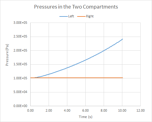
The surprising result is that even though air is being injected into the model, the pressure in both compartments remains constant at atmospheric pressure.
In the Figure 1 model, although the obstruction separates the room, air flow into the room does not raise the pressure.
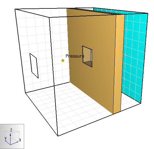
The reason for this is that FDS separates the total pressure into a "background" component and a perturbation (see Chapter 3 of the FDS Technical Reference Guide). The background pressure is typically just a hydrostatic pressure and the perturbation pressure is induced by the flow (see Chapter 9 of the FDS User Guide). The background pressure is calculated for each pressure zone, while the perturbation pressure varies spatially. In the above example, only one (default) pressure zone was defined, so it included both compartments with both the air injection and open vents. When the background pressure was calculated the injected air entered on one side of the zone and immediately vented out to the atmosphere on the other side. The pressure did not increase even though we injected air into the room. Following the instructions in Chapter 9 of the FDS User Guide, we divide the room into two pressure zones. The pressure zone on the left corresponds to our first compartment and includes the wall obstruction. The second pressure zone touches the first and corresponds to the compartment on the right with the open vent. Now when we run the model, the pressure in the left compartment increases and the pressure in the right compartment stays at atmospheric pressure. The obstruction separates the flow between compartments.
After dividing the model into two pressure zones, the pressure in the left compartment increases.
Finally, we can add a hole in the wall with a pressure control that activates the hole when the pressure reaches a set value. Now the pressure in the left compartment increases until the set value is reached. At that time the hole opens, allowing the air to vent to the atmosphere.
Warning:
In the numerical solution, a pressure relaxation time (PRESSURE_RELAX_TIME set as a PRES parameter) is used to control the pressure drop after the hole opens. Thus, the calculated rate of pressure rate change is not only based on the vent hole size.
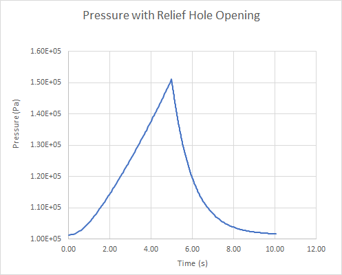
_Now the pressure reaches the set point and the vent hole opens, relieving the pressure to the atmosphere. _
Here are the FDS Input Records for the final model.
pressure_relief_vent.fds
&HEAD CHID='pressure_relief_vent'/
&TIME T_END=10.0/
&DUMP RENDER_FILE='pressure_relief_vent.ge1', DT_RESTART=300.0/
&MESH ID='Mesh', IJK=10,10,10, XB=0.0,10.0,-5.0,5.0,-5.0,5.0/
&ZONE ID='Zone01', XB=0.0,7.0,-5.0,5.0,-5.0,5.0/
&ZONE ID='Zone02', XB=7.0,10.0,-5.0,5.0,-5.0,5.0/
&REAC ID='POLYURETHANE_REAC', FYI='SFPE Handbook, GM27', FUEL='REAC_FUEL', C=1.0, H=1.7, O=0.3, N=0.08, CO_YIELD=0.042, SOOT_YIELD=0.198/
&DEVC ID='Pressure', QUANTITY='BACKGROUND PRESSURE', XYZ=3.0,0.0,0.0, SETPOINT=1.5E5/
&DEVC ID='Pressure Vent', QUANTITY='BACKGROUND PRESSURE', XYZ=8.0,0.0,0.0/
&CTRL ID='Pressure Control', FUNCTION_TYPE='ALL', LATCH=.TRUE., INPUT_ID='Pressure'/
&SURF ID='Inlet', RGB=26,204,26, VEL=-10.0/
&OBST XB=6.0,7.0,-5.0,5.0,-5.0,5.0, THICKEN=.TRUE., SURF_ID='INERT'/ Wall
&HOLE XB=5.9,7.1,-1.0,1.0,-1.0,1.0, CTRL_ID='Pressure Control'/ Vent Hole
&VENT SURF_ID='Inlet', XB=0.0,0.0,-1.0,1.0,-1.0,1.0/ Inlet
&VENT SURF_ID='OPEN', XB=10.0,10.0,-5.0,5.0,-5.0,5.0/ Open
&SLCF QUANTITY='VELOCITY', VECTOR=.TRUE., PBY=0.0/
&DEVC ID='Mass Flux at Boundary_AREA INTEGRAL', QUANTITY='MASS FLUX X', SPEC_ID='AIR', STATISTICS='AREA INTEGRAL', XB=10.0,10.0,-5.0,5.0,-5.0,5.0/
&TAIL /
To download the most recent version of PyroSim, please visit the the PyroSim Support page and click the link for the current release. If you have any questions, please contact support@thunderheadeng.com.
Related Tutorials
(Legacy) Tutorial to experience the fundamental features of PyroSim
Tutorial Demonstrating how to model pressure leakage using Pyrosim
Tutorial demonstrating how to model a fire in Pyrosim.
Video tutorial demonstrating how to avoid creating unwanted gaps in the geometry of a Pathfinder model.
Video tutorial demonstrating how to fix geometry problems related to DWG importation.
In this tutorial we show how to fix three problems that can occur when BIM (Building Information Modeling) or CAD (Computer-Aided Design) models into Pathfinder.
Tutorial to experience the fundamental features of Pathfinder
Tutorial demonstrating how to model ramps three different ways and how to import sketchup geometry in PyroSim.