Introduction
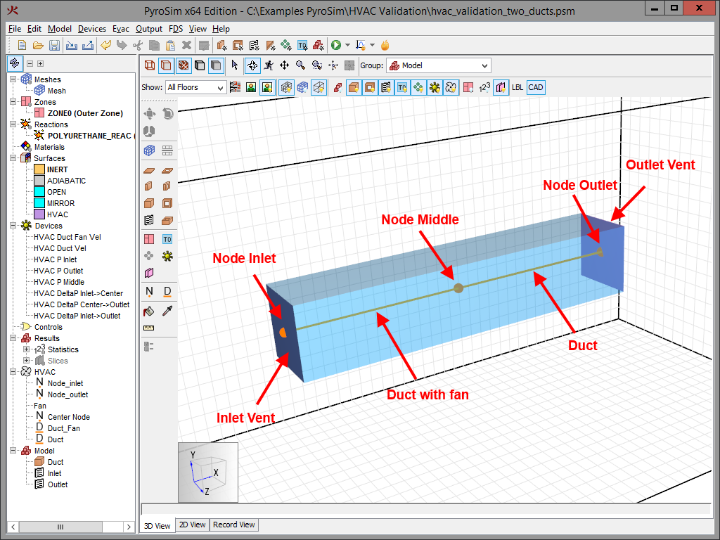
A HVAC model is shown below in Figure 1, there are three HVAC nodes and two HVAC ducts.
The duct on the left has a fan with a constant flow rate of 1.0 m3/s.
The only loss terms are due to a 0.001 m roughness in the 0.3048 m diameter ducts.
The total duct length is 2.0 m.
The duct on the right makes is easy to calculate the expected pressure drop for that section.
HVAC Pressure Drop Verification
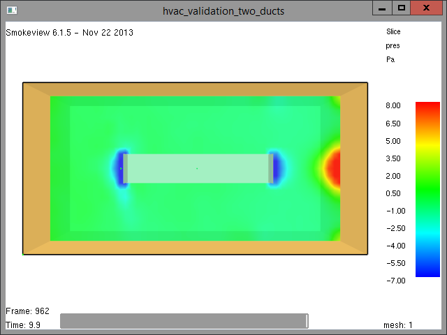
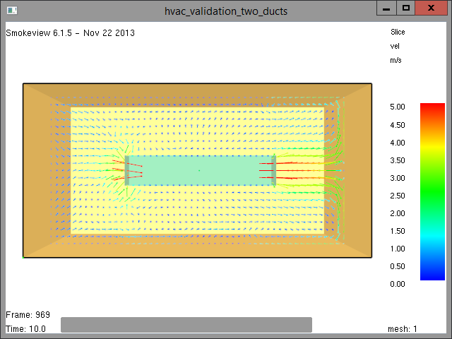
The contour plot for this simulation is shown in Figure 2 and the velocity plot is shown in Figure 3. The pressure contours show low pressure near the inlet and outlet, where the velocity is high, and a high pressure region where the exit flow impinges on the wall.
The calculation for the expected pressure loss in the duct without a fan was done in the Duct Loss Due to Wall Friction Calculator .
The duct velocity is calculated to be 13.7 m/s and the pressure loss calculated to be 10.1 Pa.
The duct loss calculation is taken from the FDS Technical Reference Guide.
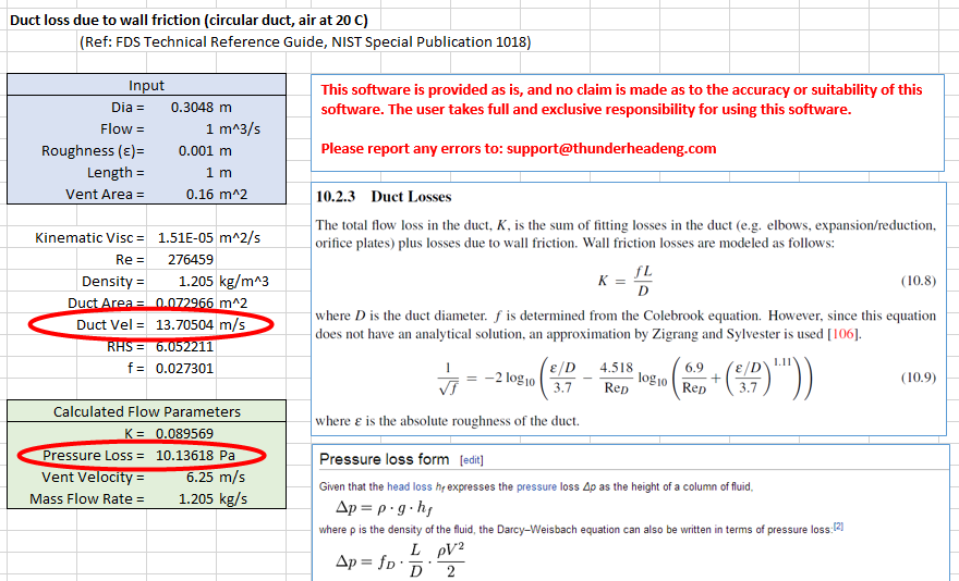
Figure 5 and Figure 6 below show the FDS results for the velocity in the duct and the pressure drop. The values match those calculated in the spreadsheet.
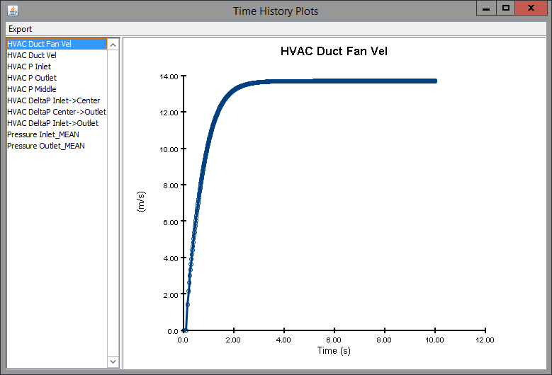
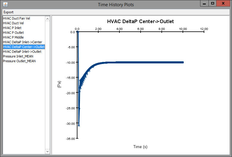
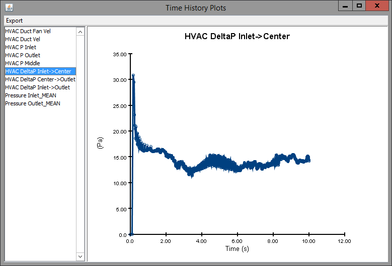
The pressure difference in the duct with the fan shows the pressure increase needed to maintain the specified fan velocity.
This problem verifies the flow calculation in the section of the duct without a fan, where the velocity and pressure drop match the expected values.
The expected speed at the vent outlet is 6.25 m/s.
The gas velocity measurement device placed at the center of the vent records a speed of 5.8 m/s.
Keeping in mind that Smokeview does interpolation, this is fairly close to 6.25 m/s.
To download the most recent version of PyroSim, please visit the the PyroSim Support page and click the link for the current release. If you have any questions, please contact support@thunderheadeng.com
Related Tutorials
Tutorial demonstrating how to create and FDS Velocity Patch in Pyrosim.
Tutorial demonstrating how to model jet fans in Pyrosim.
Tutorial demonstrating how to model critical velocity in Pyrosim using the example of a tunnel fire.
(Legacy) Tutorial to experience the fundamental features of PyroSim
Tutorial demonstrating how to use the Combustion Calculator for HCN, HCl and Soot in Pyrosim.
How to simplify post-processing data collection with seasonal scenarios and scheduled stairwell temperatures.
Tutorial demonstrating how to model a pressure relief vent in Pyrosim.
Tutorial demonstrating how to use PyroSim/FDS to Maximize Solar Panel Convective Cooling.