Introduction
The BRE guide Design methodologies for smoke and heat exhaust ventilation (Morgan et al. 1999) summarizes the advice available from the BRE Fire Research Station (UK) to designers of atria and other buildings. Annex D of the BRE document compares different fire spill-plume calculation methods applied to a multistorey shopping mall.
The purpose of the BRE guide is to provide practical guidance on the design of Smoke and Heat Exhaust Ventilation Systems (SHEVS) for atria and other buildings. It both reflects current knowledge and draws on the authors' experience of design features required for regulatory purposes in many smoke-control applications. Annex D provides example calculations for a large-area smoke reservoir with a free plume rising from the spill edge.
FDS is the fire dynamics simulator developed at NIST (US). It is a computational fluid dynamics (CFD) model of fire-driven fluid flow. The software solves numerically a form of the Navier-Stokes equations appropriate for low-speed, thermally-driven flow, with an emphasis on smoke and heat transport from fires.
We compare Fire Dynamics Simulator (FDS) results to the calculations in BRE Annex D in this post.
Annex D Calculation
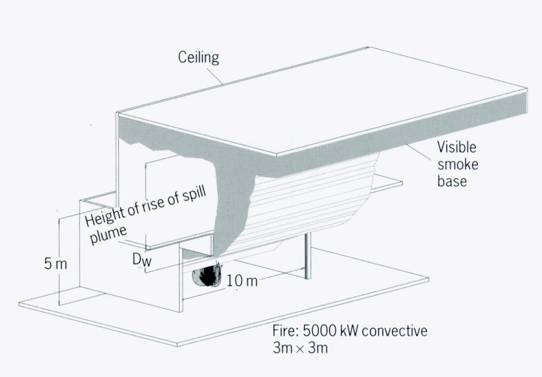
The example calculation represents a fire in a typical shop in a multistory shopping mall. The fire is located in a shop and the smoke travels out of the shop and is channelled to a length of spill edge. The free plume rises from the spill edge to the ceiling. Details of the geometry are:
- Shop width =
10 m, with no downstand facia. - Storey height =
5 m, for simplification. - Convective heat flux =
5000 kW, coming from a3 m x 3 mfire. - Smoke is channelled directly to the spill edge over a length of
10 m. - No downstand at spill edge.
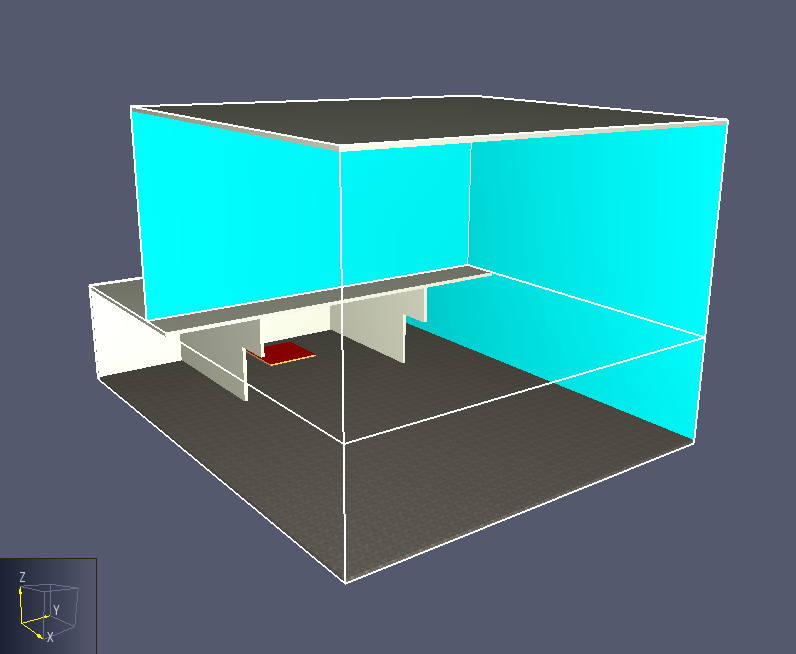
The corresponding FDS model is shown below in Figure 2.
The dimensions are as specified for the calculation.
The smoke curtains on either side of the shop extend 2 m below the spill edge.
The boundary of the problem is open, except for the floor, ceiling, shop back wall, and balcony.
This is consistent with the smoke pattern assumed in Figure 1 for a free plume.
The total Heat Release Rate was 7692.3 kW, with a 35% radiative fraction, giving a convective heat release rate of 5000 kW.
The characteristic fire diameter (D*) for the fire is 2.2 m.
The mesh size was 0.2 m, approximately equal to D*/10, a size that should give reasonable results.
Comparison of Example Calculation and FDS Results
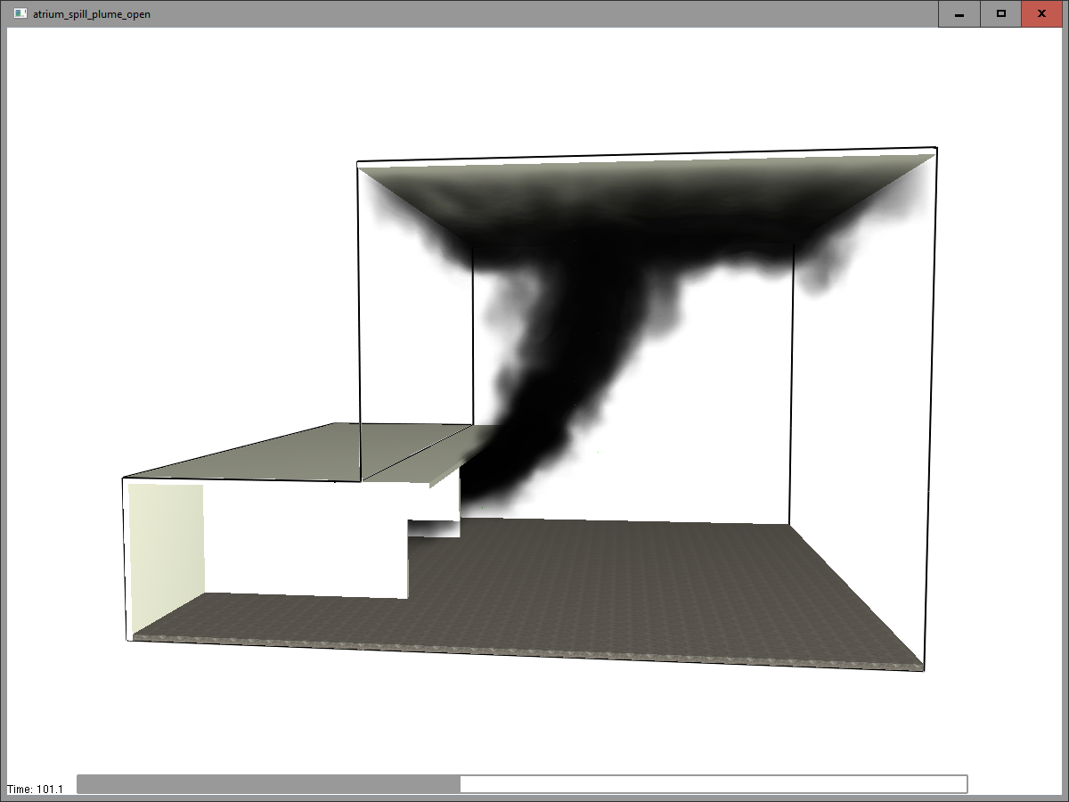
We will now proceed through each step of the Annex D calculation and compare the calculations with the FDS results. An overview of the FDS results is shown in Figure 3.
Calculation 1: Mass Flow Rate at Spill Edge
Following the procedure in Annex D, we first calculate the mass flow rate of smoky gases passing from the shop to the spill edge. Using BRE equation 5.7:
where:
\(M_{w}\) is the mass flow rate of smoky gases passing through a vertical opening (kg/sec)
\(C_{e}\) is the entrainment coefficient (0.34 kg/sec-m5/2 for small rooms)
\(P\) is the perimeter of the fire (m)
\(W\) is the width of the opening (m)
\(h\) is the height of the top of opening above the floor (m),
\(C_{d}\) is the coefficient of discharge for the opening (1.0 for no downstand),
The calculated result is a mass flow rate of 29.2 kg/s.
The FDS results give 36.3 kg/s, 25% larger than the calculation.
Calculation 2: Depth of Smoke Layer at Spill Edge
We calculate the depth of the smoke layer at the spill edge using BRE equation 5.11:
where:
\(D_{B}\) is flowing smoke layer depth under the balcony (m)
\(C_{d}\) is the coefficient of discharge for the opening (1.0 for no downstand)
\(M_{B}\) is the mass flow rate under the balcony, calculated in Calculation 1: Mass Flow Rate at Spill Edge (kg/sec)
\(T_{l}\) is the mass-weighted average absolute temperature of gas layer (K)
\(\theta_{l}\) is the temperature rise above ambient in the gas layer (K)
\(W_{B}\) is the balcony channel width (m)
\(T_{0}\) is the absolute ambient temperature (K)
The calculated result is a layer depth of 1.19 m.
The FDS results give a layer depth at the center of the balcony edge of 1.63 m, 37% larger than the calculation.
Calculation 3: Entrained Flow in Spill Plume
The BRE document provides an approach in Annex E, but also notes that a simpler calculation using the Thomas method (equation 6.5) with the Poreh method (equation 6.6) of calculating \(\rho\) gives the same result, so we use the Thomas/Poreh approach. First calculate \(\rho\) using BRE equation 6.6 and 6.4:
where:
\(C_{e}\) is the entrainment coefficient (0.44 for a free plume),
\(\rho_{0}\) is the density of ambient air (kg/m3),
\(L\) is the length of spill edge (m),
\(Q_{w}\) is the convective heat flux (kW).
Knowing \(\rho\), we then calculate the mass flow rate in the plume using BRE equation 6.5:
where:
\(M_{1}\) is the mass flow of smoky gases at height \(h_{b}\) (kg/s),
\(\rho\) is the density of warm gases at height \(h_{b}\) (kg/m3),
\(c\) is the specific heat of air (kJ/kg-K),
\(\rho\) is the height of the virtual source below void edge (m), and
\(h_{b}\) is the height of rise of thermal plume above void edge (m).
The calculated result is a layer depth of 1.19 m.
The FDS results give a layer depth at the center of the balcony edge of 1.63 m, 37% larger than the calculation.
\(h\) is the height of the top of opening above the floor (m),
A comparison of the Thomas/Poreh calculation (described in BRE) and FDS results for mass flow in the plume is shown in Figure 4.
The shopping mall ceiling height is 15 m and the shop balcony height is 5 m, so the distance from the balcony edge to the ceiling is 10 m.
The Thomas/Poreh calculation does not account for ceiling height, while the FDS calculation includes the hot gas layer at the ceiling.
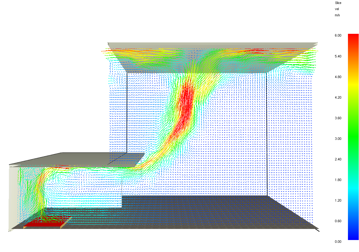
This layer affects flow about 2-3 m below the ceiling, shown by the velocity vectors in Figure 5.

Figure 5 shows a slice of the model with the velocity vectors for the FDS calculation at 100 sec.
You can see the formation of layers at the balcony and shopping mall ceiling.
Note that the FDS solution is dynamic and varies with time.
This is a typical result.
Summary
The correlation between the calculations described in the BRE document and FDS is very satisfactory. The BRE calculations fit to a range of experimental data, not exact results for this particular problem. Hopefully, this tutorial has provided you with more confidence in both the BRE calculations and FDS.
To download the most recent version of PyroSim, please visit the the PyroSim Support page and click the link for the current release. If you have any questions, please contact support@thunderheadeng.com
Bibliography
Morgan, H.P., B. K. Ghosh, G. Garrad, R. Pamlitschka, J-C. DeSmedt, and L. R. Schoonbaert. 1999. Design Methodologies for Smoke and Heat Exhaust Ventilation. https://www.brebookshop.com/details.jsp?id=325115.
Related Tutorials
Evacuation simulation of a center-platform station using Pathfinder, then comparing results with NFPA 130 and SFPE calculations.
Tutorial demonstrating how to model critical velocity in Pyrosim using the example of a tunnel fire.
Tutorial demonstrating how to model Smoke Visibility and Obscuration in Pyrosim.
Tutorial demonstrating how to model jet fans in Pyrosim.
Tutorial demonstrating how to create and FDS Velocity Patch in Pyrosim.
Tutorial demonstrating how to calculate complex stoichiometry in Pyrosim.
Tutorial demonstrating how to integrate Fractional Effective Doses with Evacuation Results.
Tutorial demonstrating how to verify HVAC Pressure Drop in Pyrosim.