Overview
This is the fifth tutorial in our PyroSim Fundamentals tutorial series, intended for new PyroSim users. In this tutorial, we will demonstrate how to model some basic fire protection systems in PyroSim. This tutorial will teach you the basics of the modeling tools provided by PyroSim, and NOT about the engineering methodology behind fire protection engineering. For that type of information, use resources like the SFPE Handbook of Fire Protection Engineering and your local code standards. We will also demonstrate how to configure your PyroSim model to react to its own state using Controls.
Before Starting
Before beginning this tutorial:
- Create the prerequisite model in the Importing Geometry and Materials and Layered Surfaces tutorials.
- Alternatively, download the complete files for this tutorial: Fire Protection Systems.
- Visit the latest version of the PyroSim User Manual for reference throughout this tutorial.
- Download the latest version of the FDS User’s Guide from the NIST FDS-SMV Manuals page.
Introduction
Fire protection systems are combinations of equipment, such as fire suppression, alarm, and smoke control systems, used in tandem to protect a given space and its occupants against fires. These systems are often modeled in design fire scenarios to ensure compliance with code requirements, and more importantly, to ensure that they will perform their role in protecting occupants. Thankfully, PyroSim and FDS provide tools to model a wide array of fire protection systems, including sprinkler, smoke detector, alarm, and ventilation systems.
Additionally, PyroSim and FDS provide tools, called Controls, that allow you to configure your model to react to its own state changes. An example of this might be internal doors opening when an alarm system goes off, to model occupants opening doors to exit a building during a fire alarm.
We will model both a simple fire protection system and a simple Control in the model we have created in previous PyroSim Fundamentals tutorials.
Sprinklers
The first step in creating our fire protection system is to create a Sprinkler. Sprinklers in PyroSim are specialized Devices that will spawn water Particles to suppress a fire once their triggering condition is met. By default, Sprinklers are triggered by a Temperature Link. Temperature Links allow you to specify sprinkler properties provided by your sprinkler manufacturer in order to model your sprinkler as realistically as possible. FDS then uses these parameters in its Response Time Index algorithm to model sprinkler activation. Like other objects we have talked about before, you can create libraries of Temperature Links in order to easily re-use links across your projects.
We will use a default generic temperature link provided by PyroSim. These generic links are not meant to accurately model any specific sprinklers and are only intended as examples of valid generic configurations.
Creating a Sprinkler
To create a Sprinkler in your model:
- Use the Devices > New Sprinkler action.
- In the Sprinkler dialog, change the name to
Sprinkler, and set the Location toX=11.0m, Y=20.5m, Z=11.8872m. - Leave the Activator set to Temperature Link, with the
Generic Commercial Linkselected in the dropdown. - Click Ok to create the sprinkler.
This sprinkler will activate at the 68.33°C Activation Temperature set in the Generic Commercial Link and will disperse water droplets to suppress the fire in the model.
Vents
As described in the Your First Fire tutorial at the beginning of this series, Vents are 2D planes that allow us to apply a set of boundary conditions to cells in our model. In this tutorial, we will create a Vent to act as a rudimentary smoke control system. The geometry in this model does not represent mechanical ventilation space so the placement of this Vent will not be realistic, however it will showcase how to set up such a Vent using the tooling provided in PyroSim.
Creating a Vent
Before creating the Vent, we need to define the boundary conditions that we wish to apply. We do this by defining a Surface. To define this Surface:
- Open the Edit Surfaces dialog using the Model > Edit Surfaces action.
- Click New to open the New Surface dialog.
- Enter the name
Exhaust, then set the Surface Type toExhaust. - In the Air Flow tab for the
Exhaustsurface, set the Specify Volume Flow field to \(10.0m^3/s\). - Click OK to save the Surface.
The boundary conditions are now set up for use with the Vent. To create the Vent:
- Create a new Vent by using the Model > New Vent action.
- In the Vent Properties dialog, give the Vent and ID of
Exhaust. - Set the Surface dropdown to the
ExhaustSurface you just created. - Switch to the Geometry tab.
- In the Geometry tab, set the Plane to
X, and set it to a value of14.06m. - Set Min Y to
21.0m. - Set Max Y to
22.0m. - Set Min Z to
11.3m. - Set Max Z to
11.8m. - Click OK to create the Vent.
The Vent you just created should appear on the wall next to the Door Obstruction.
When active, this Vent will exhaust gas from the cells that it touches.
However, in a real smoke control system, this Vent would not be active all the time.
It would only activate when smoke was detected in the building.
To replicate this behavior in our model, we will use Controls.
Controls
Controls, as their name implies, are used to control the state of various objects in your model.
Most objects have a state that can be managed with a Control.
In this example, we will create two Controls.
One Control will activate the Exhaust Vent you created in the previous section, and the second Control will deactivate the Door obstruction in the model, simulating an occupant opening the door and evacuating the fire.
Creating Controls
We will first create a Control for the Exhaust vent.
To create this Control:
- Open the Activation Controls dialog by using the Devices > Edit Activation Controls action.
- Click New to open the New Control dialog.
- Name the new control
Exhaust Controland leave the Control Type set to Activation. - Click OK to create the Control.
- With
Exhaust Controlselected, set the Input Type to Detector. - Set the Action to Perform to Activate.
At this point the Control is created and ready to configure, however it currently does not control anything.
- In the text box of the Activation Controls dialog, click the first hyperlink to open a search widget.
- Search for "Exhaust", then click the checkbox next to the
ExhaustVent that you created in the previous section, then click OK. - In the text box, click the second hyperlink, then click the checkbox next to the
Smoke DetectorDevice, then click OK. - In the text box, select the last hyperlink and set the delay time to
30.0s, then press Enter. - Click OK to save the Control.

This Control now controls the Exhaust Vent.
It will enable the Vent 30 seconds after the Smoke Detector reaches its smoke detection threshold.
After activation, the Vent will then provide a flow, defined in the Exhaust Surface definition, to exhaust smoke from the room.
One other use of Controls is to manipulate the geometry in your model to simulate things like doors opening/closing, or windows breaking due to heat.
Let’s create another quick Control to remove the Door Obstruction 5 seconds after the Smoke Detector activates.
To do this:
- Create another Activation Control named
Door Control. - Set the Control type to Detector, and the Action to Perform to Deactivate.
- Using the methods you learned from the
Vent Control, configure the control so that it deactivates theDoorObstruction whenSmoke Detectoractivates, delayed by5.0s.
Now, your model has another Control that will remove the Door Obstruction 5 seconds after the Smoke Detector activates, simulating a person opening the door to evacuate the room.
Results
The modeling of our simple Fire Protection System is now complete. The next step is to run the simulation and view the results.
Device and Control results
To run the simulation and view the results:
- Run the simulation using the
 Run icon.
 - Once the simulation is finished, click the arrow next to the
 Time History plots icon, and select Plot Device Results.
 - Select the
SprinklerDevice and view the chart.
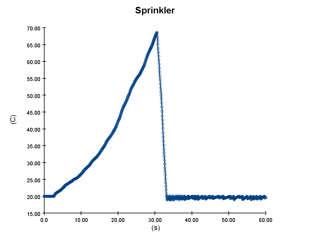
As you can see in Figure 6, Sprinkler Devices record Temperature by default.
As shown in the chart data, the Temperature continually rises until roughly t=30s, where it passes the default 68.33°C Activation Temperature of the Generic Commercial Link Sprinkler Link Model.
At that point, we can assume that the Sprinkler activates to suppress the fire (we will verify the exact time later).
Sprinkler Device.- Close the Time History Plots window, then click the arrow next to the Time History plots icon, and select Plot Control Results.
- Select the
Exhaust ControlControl and view the Chart.
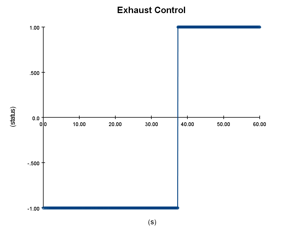
As you can see in Figure 7, Controls provide data in terms of their activation status.
A value of -1 indicates not activated, and a value of 1 indicates activated (please see the NOTE section below for a little more information on this).
With this information, it appears that the Exhaust Control activates at around 37 seconds into the simulation.
Given that we configured this Control to activate 30 seconds after the Smoke Detector, we can extrapolate that the Smoke Detector activated at approximately 7 seconds.
Again, we will verify the exact activation times later, but this appears to show that our simulation behaved as expected.
Exhaust Control Control- Select the
Door ControlControl and view the Chart.
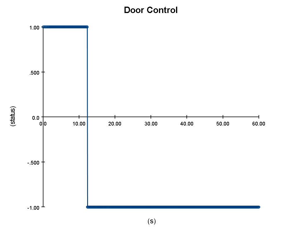
The Door Control also appears to have behaved as expected.
From Figure 8, you can see that the Control appears to have activated at roughly 12 seconds.
Given that it was set on a 5 second delay following the activation of the Smoke Detector Device, it appears again that the Smoke Detector activated at approximately 7 seconds.
Door Control Control- Close the Time History Plots window, then use the Analysis > Open Results Folder action.
- In the Windows Explorer, double-click the
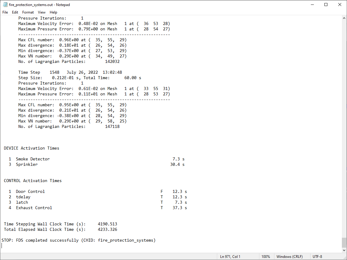
fire_protection_systems.outfile to open it in Windows Notepad. - Scroll to the bottom of the file, to the sections labeled DEVICE Activation Times and CONTROL Activation Times.
Figure 9 shows the exact activation times of the Devices and Controls in the model.
As you can see, the Sprinkler Device activated at t=30.4s, the Smoke Detector Device at t=7.3s, the Door Control Control at t=12.3s, and the Exhaust Control Control at t=37.3s.
All those values are exactly as expected.
3D Control results
The next thing to do is view these results in 3D. To do this:
- Open the PyroSim Results viewer by clicking Show Results in the Run Simulation dialog, or by clicking the
 View Results icon.
 - Use the View > Floor Settings action to open the Floor Settings dialog.
- In the Floor Visibility dropdown, select
9.144, orFloor 9.1. This is elevation ofLevel 4as defined in the PyroSim preprocessor, just represented in meters. - Locate the room of interest by panning and rotating the camera.
- Press the
 Play icon to begin the results playback.
With no results visualization selected, as is the default when opening the Results Viewer, the playback will show any geometry changes that take place in your model.
As you can see in Figure 10, the Door Obstruction is deactivated, and the Exhaust Vent is activated at the proper times.
Playback stops after the last geometric event in the model, which in this case is the activation of the Exhaust Vent at t=37.4s.
Now let’s see the full playback of the model.
- Double-click the 3D Smoke and the Particles visualizations to enable them in the 3D playback window.
- Press the Play icon to begin the results playback.
As you can see in Figure 11, the fire protection systems and controls in our model work as expected. Shortly after the fire begins, the smoke detector activates, which triggers the opening of the door, simulating the evacuation of the occupant. Once the fire heats the sprinkler to 68.33°C, the sprinkler is activated and begins dispersing water to help suppress the fire. And lastly, 30 seconds after the smoke detector has activated, the Exhaust vent is activated, helping to remove a large amount of smoke from the room.
Conclusion
You should now be familiar with how you can model Fire Protection Systems and Controls in PyroSim. These systems can obviously get much more complex than the simple one demonstrated here, so it is a good idea to test your systems in small, discrete, fast-to-run simulations before trying them in larger ones. It will save you a lot of time and frustration, and will help ensure that your full model behaves as expected.
To download the most recent version of PyroSim, please visit the PyroSim support page and click the link for the current release. Please contact support@thunderheadeng.com with any questions or feedback regarding our products or documentation.
Bibliography
Related Tutorials
This tutorial will walk you through adding additional basic data outputs to your PyroSim model.
This tutorial will walk you through adding and layering materials, allowing for more complex heat transfer in your PyroSim model.
This tutorial will walk you through creating your first ever PyroSim fire model.
This tutorial teaches the user how to create circulation movement using Queues in an example cafeteria model.
Tutorial demonstrating circulation movement in a cafeteria model.