Overview
This is the third tutorial in our PyroSim Fundamentals tutorial series, intended for new PyroSim users. In this tutorial, we will demonstrate how to import BIM geometry files into PyroSim models, as well as teach you the basics of how this geometry is converted to FDS Obstructions. Additionally, you will set up this model for use in future Fundamentals tutorials and refine the skills you learned in the previous tutorials.
Before Starting
Before beginning this tutorial:
- Understand the basics of creating a fire by completing the Your First Fire tutorial.
- Understand the basics of data output by completing the Basic Data Output tutorial.
- Download the files for this tutorial: Importing Geometry
- Visit the latest version of the PyroSim User Manual for reference throughout this tutorial.
- Download the latest version of the FDS User’s Guide from the NIST FDS-SMV Manuals page.
Introduction
With many models, you will have existing geometry created in external CAD tools such as Revit or Sketchup prior to creating your PyroSim model. This geometry is often created by an architect that has spent many hours crafting detail in the model. Re-creating this geometry from scratch just for a fire model would be tedious, and would also not achieve the same level of detail as provided in the external model.
PyroSim saves you the time and hassle of recreating this geometry by providing BIM import capabilities for many common CAD filetypes. PyroSim uses this geometry to generate FDS code, meaning that you only need to adjust your existing geometry to begin creating your fire model, rather than recreating it all.
Importing Geometry
In this tutorial, you will be importing our Getting Started IFC model to create a PyroSim model. The model you make here will be used in this and future tutorials.
International Foundation Class (IFC) files, like our Getting Started IFC model, are just one of the supported CAD file types. An IFC file is a very common, universal format, for BIM data. You can see the full list of supported CAD filetypes in the Importing CAD Files Section of the PyroSim User Manual.
Importing the CAD file into PyroSim is straightforward. To begin importing this model:
- Extract the Importing Geometry zip file that you downloaded in Before Starting.
- Open a new PyroSim window.
- In the PyroSim window, click the
 Save icon to bring up the save dialog.
 - Save the model as
importing_geometry.psm. - Back in the main window, click the Import FDS/CAD File action under the File menu.
- In the file dialog, select the
Getting Started Model.ifcfile that you unzipped earlier, then click Open.
You should now see the import dialog, shown in Figure 1. This dialog automatically detects the type of CAD model you are trying to import and walks you through the steps needed to import it. It also provides tooling to adjust your model for use in PyroSim. We will cover the most commonly used options in this tutorial, but for a full breakdown of all options in the dialog, see the Importing CAD Files Section of the PyroSim User Manual.
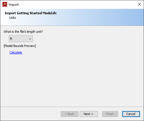
- Set the file’s length unit dropdown to
ft, then click Next.
- Leave the Lighting and Objects options as set by default and click Next.
- Leave the Materials options as set by default and click Next.
You should now see the geometry page of the import dialog, shown in Figure 2. As its name suggests, this page contains tools used for correcting and manipulating imported geometry.
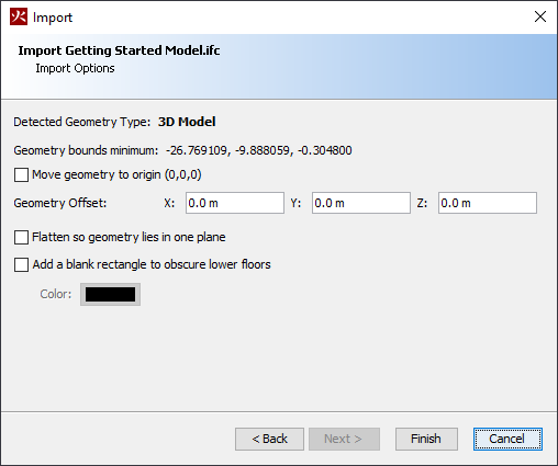
- Check the box next to Move geometry to origin (0,0,0).
- Leave the Geometry Offset set to
0.0m, 0.0m, 0.0m.
- Click Finish to finalize the import process.
- Click the Save icon to save your model.
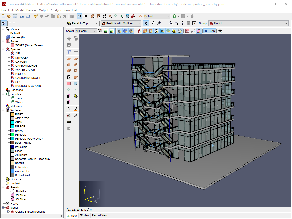
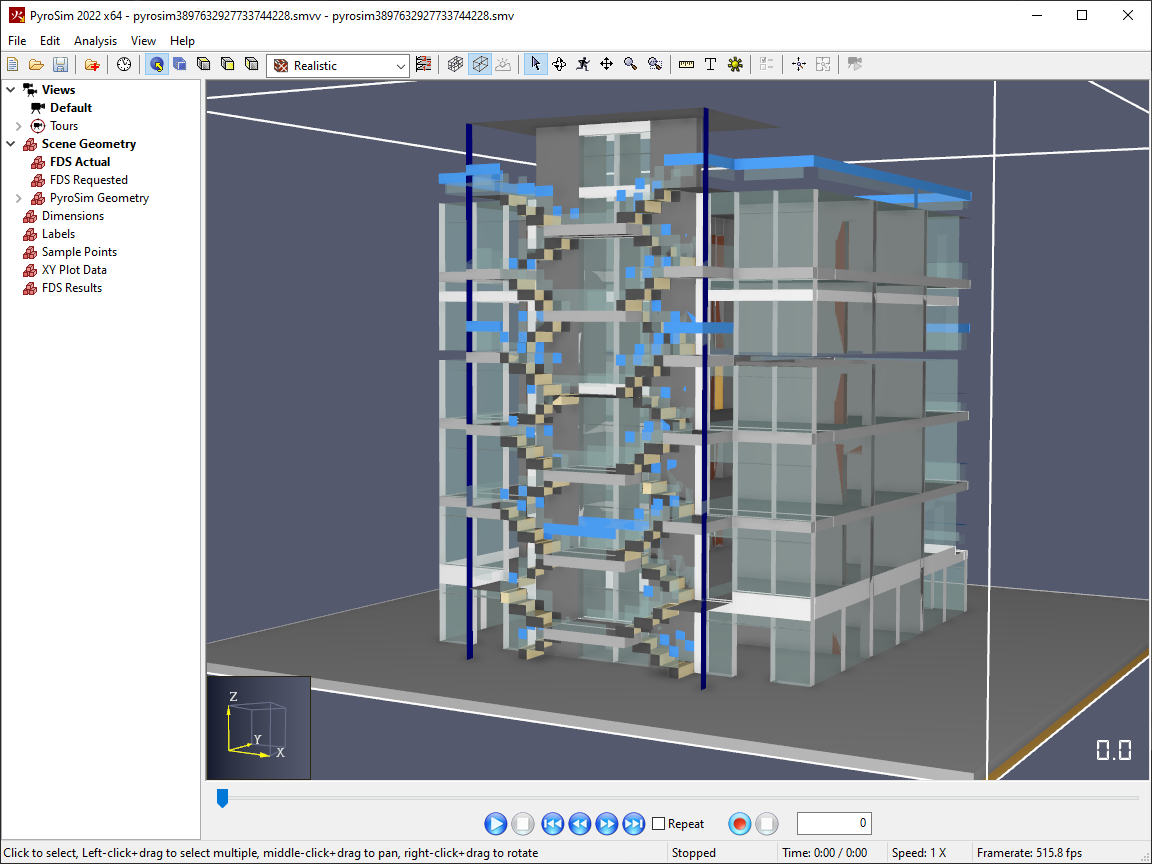
You should now see the Getting Started model, shown in Figure 3 imported and ready for you to use in your fire models.
Creating a model with the Imported Geometry
With the CAD model imported, let’s take a look at how to use the geometry and create a fire model in PyroSim.
Creating Floors
This is the first model in the Fundamentals tutorials that has more than one floor. In all likelihood, the majority of building models that you will come across will involve multiple floors. If you were to try to create a fire scenario on a single floor now, much of the model’s geometry would get in the way of your work. Thankfully, PyroSim provides a simple floor system that allows you to easily organize and view your geometry by elevation, rather the imported model tree hierarchy.
To define floors in the model:
- Switch the unit system to English units by clicking the
 icon.
icon.
- Click the
 Define Floor Locations icon to open the Manage Floors dialog.
 - Select the
Defaultfloor, then click Remove Row. - Click the Add Floor button.
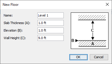
- In the New Floor dialog, enter the Name
Level 1, Slab Thickness1 ft, Elevation1 ft, and Wall Height9 ft. - Click OK to exit the New Floor dialog.
Level 1 floor.You have now created your first floor in the model.
You should now see the Level 1 row in the Manage Floors dialog’s table.
To view this floor:
- Click OK to close the Manage Floors dialog.
- In the Show dropdown, shown in Figure 6, select the
Level 1floor that you just created.
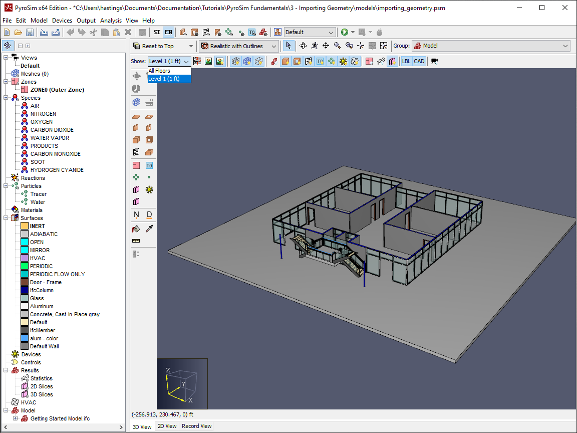
Level 1 floor in the Show dropdown.Your model should now resemble Figure 6.
Note that all of the geometry outside the bounds of the Level 1 floor is not visible in the 3D view, however it is still present and active in the Navigation View.
This allows you to easily manipulate the Level 1 floor and define your model.
To add the rest of the floors to the model:
- Re-open the Manage Floors dialog by clicking the icon.
- Click the Add Floor button.
- Re-name the floor to
Level 2. - Click OK to create the floor.
- Repeat steps 10-12 until you have defined Levels 1-7.
- Rename
Level 7toRooftop, and change its Wall Height to10ft. - Click OK to exit the Manage Floors dialog and save your floor changes.
- Switch back to metric units using the
 icon.
icon.
You have now defined all of the floors for this model.
It should now be much easier to view each individual floor for editing.
You can also use the All Floors selection in the Show dropdown to show all of the visible geometry in the model.
Setting up the Fire Model
Now, you will create a simple fire in this model similar to the one that you created in the Your First Fire tutorial. The instructions for this section will be brief. If you struggle at all here, refer back to the Your First Fire tutorial for more detailed steps on creating the fire. To create the fire:
- Add the
SFPE WOOD_OAKreaction to the model from the PyroSim reaction library in the Edit Reactions dialog. - Create a new burner surface name
Firein the Edit Surfaces dialog. - Set the Heat Release Rate Per Unit Area of the
Firesurface to660 kW/m2in the Heat Release tab of the Edit Surfaces dialog. - Select the
Level 4floor in the Show dropdown. - Draw a
1m x 1m x 0.4mslab namedFireusing the Top Down 2D View in one of the rooms furthest from the stairs. - Set the Z Location of the slab to
9.4488m. - Set the top face of the
Fireobstruction to use theFiresurface.
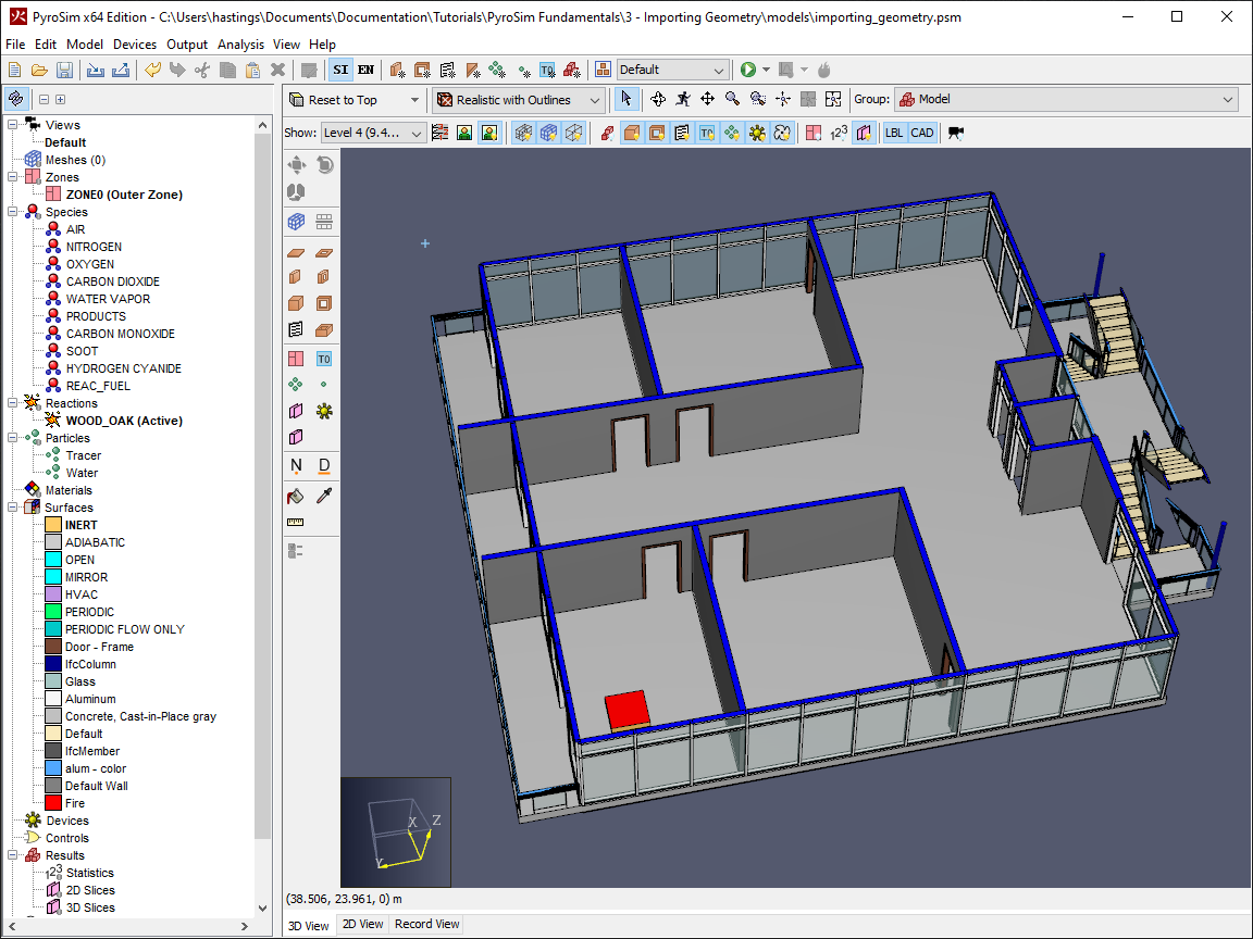
Level 4 floor in the Show dropdown and defining the basic fire.- Add a mesh to the model using the default geometry bounds, but set the X, Y, and Z cells to
85, 80, 55. - Add an OPEN mesh boundary condition by right-clicking the Mesh in the Navigation View, and selecting the Open Mesh Boundaries action.
- Remove the OPEN boundary at ZMIN by deleting the associated ZMIN vent in the new
Mesh Boundary Ventsgroup in the Navigation View.
- Draw a
2.2mtall Obstruction namedDoorin the doorway of the room with theFireobstruction.
- In the 2D Top-down view, create a Smoke Detector device named
Smoke Detectorin front of the door atZ = 11.8872mpointed in theZ = -1.0orientation.
- In the 2D Top-down view, create a Wall Temperature device named
Wall Temperatureon a wall in the room atZ = 10.668m. - Open the Wall Temperature device and set the Normal of Solid field to the appropriate value for the selected wall.
- Set the simulation end time to
60sin the Analysis > Simulation Parameters dialog.
Your fire model using imported geometry is now finished and ready for simulation, as well as for use in upcoming tutorials in this series.
How does PyroSim use imported geometry?
Take a quick pause here to look at the model and understand how PyroSim is using the geometry that you imported in this tutorial. As mentioned in the Your First Fire tutorial, FDS only understands geometry as Obstructions. It does not understand your imported CAD geometry. Because of this fact, PyroSim transforms your geometry to Obstructions.
In addition to that transformation, FDS performs its own transformations that snap your geometry and other objects to the computation mesh. These transformations make it important to examine the transformed model before you run the simulation. Remember, simulations can take days to finish. You do not want to spend that computation time simulating your model, only to find out that you need to correct geometry errors and run it again.
PyroSim provides some tooling to help you in verifying your geometry.
The first tool is the ![]() Preview FDS Blocks feature, available in the View toolbar at the top of the model window.
Activating this view, shown in Figure 11, will show you an approximation of what your model will look like based on the geometry and the Mesh resolution that you have defined.
Preview FDS Blocks feature, available in the View toolbar at the top of the model window.
Activating this view, shown in Figure 11, will show you an approximation of what your model will look like based on the geometry and the Mesh resolution that you have defined.
Notice how different the model looks in Figure 11 before and after the Preview FDS Blocks feature is activated. The glass panes and some of the walls in the model become thin, because the Obstructions that define them are thin enough that both opposing faces in the Obstruction snap to the same Mesh cell face. Complex geometry such as the stairs in the model, become much more blocky, as they are again snapped to the Mesh cell faces. In this model, you used a very coarse Mesh cell size because we don’t want you spending hours simulating a tutorial. Decreasing the Mesh cell size (a.k.a. increasing the Mesh Resolution) will result in smaller cells, which will in turn cause your final model to more closely resemble the imported geometry, however this has the tradeoff of increased simulation time for the extra cells.
Remember, however, that Preview FDS Blocks only gives you an approximation of the model as FDS would see it. To view the model exactly as FDS will see it, use the Preview Model in Results action in the Analysis menu. This will run your PyroSim geometry through the initial simulation phase of FDS, which generates the final geometry. You can then use the FDS Actual geometry view in PyroSim Results to view the actual geometry created by FDS, and can confirm your model setup prior to running the simulation.
The geometry conversion described here is a frequent cause of simulation errors when using imported geometry, so it is important to verify it prior to simulation using the methods described above. This issue can frequently be resolved by enabling the Rasterize axis-aligned and Force all obstructions to be thickened options available in Analysis > Simulation Parameters > Angled Geometry.
Simulation and Results
To run the simulation and view the results:
- Run the simulation using the
 Run icon.
 - Once the simulation is finished, open the PyroSim Results viewer by clicking Show Results in the Run Simulation dialog, or by clicking the
 View Results icon.
 - Double-Click 3D Smoke in the Results Navigation View.
- Press the
 Play icon to begin the results playback.
Notice how in Figure 13 there is a small gap between the Fire Obstruction and the smoke visualization.
This is because FDS slightly adjusted the size of the Fire Obstruction, and it uses that transformed geometry for calculations.
Figure 14 shows the smoke visualization paired with the FDS Actual geometry.
Notice that it is an exact fit for the visualization.
Note that there is also an FDS Requested geometry visualization. This geometry is the geometry that PyroSim requested of FDS in the FDS input file. This may not be exactly the same as the FDS Actual geometry, and is another good comparator for troubleshooting your model set-up in the future.
Conclusion
You should now be familiar with how to import BIM geometry into PyroSim models, and how this geometry is transformed to generate the final FDS model. You should also now have a model prepared for the remainder of the Fundamentals tutorials.
You can download the complete model files for this tutorial here: Importing Geometry.
To continue building your skillset, check out the related tutorials linked below.
Please contact support@thunderheadeng.com with any questions or feedback regarding our products or documentation.
Related Tutorials
(Legacy) Tutorial to experience the fundamental features of PyroSim
Video tutorial demonstrating how to fix geometry problems related to DWG importation.
In this tutorial we show how to fix three problems that can occur when BIM (Building Information Modeling) or CAD (Computer-Aided Design) models into Pathfinder.
Tutorial demonstrating how to import IFC files to Pathfinder.
Tutorial Demonstrating how to model pressure leakage using Pyrosim
Tutorial to experience the fundamental features of Pathfinder with a mixed purpose multi-floor building
Tutorial demonstrating how to model ramps three different ways and how to import sketchup geometry in PyroSim.
Tutorial demonstrating how to make ramps in Pathfinder.