Overview
This is the first tutorial in our PyroSim Fundamentals tutorial series, intended for new PyroSim users. In this tutorial, we will demonstrate how to create a basic fire simulation in PyroSim, and explain the basic underlying FDS concepts. By the end of this tutorial, you will have learned how to navigate the PyroSim interface, create model geometry, define a fire, define a mesh, run the simulation, and view the results.
This is the first tutorial in the updated PyroSim Fundamentals series. To view the old tutorials, see the Legacy Fundamentals Tutorials.
Before Starting
Before beginning this tutorial:
- Download and install the latest version of PyroSim from the PyroSim Support Page.
- If you haven’t already, get a free 30-day trial license.
- Visit the latest version of the PyroSim User Manual for reference throughout this tutorial.
- Download the latest version of the FDS User’s Guide from the NIST FDS-SMV Manuals page.
Introduction
Welcome to the very first tutorial on creating fire models in PyroSim. Before jumping in to things, it is important to briefly go over what PyroSim is.
PyroSim is a Graphical User Interface (GUI) that provides a 'pre-processor' (Model Builder) and 'post-processor' (Results Viewer) for the Fire Dynamics Simulator (FDS), which is developed and maintained by the National Institute of Standards and Technology Fire Research Division (NIST). FDS is a computational fluid dynamics (CFD) model that realistically simulates the dynamics of combustion for low-mach flows. Such models are useful in the fields of fire protection and fire forensics, as well as many others, to explore how fire would behave in various scenarios. While FDS is very useful, the default requirements that users create models using a text-based input file, written in the Fortran namelist syntax, increases the barrier to entry for an average user.
PyroSim makes it easier to create FDS models by writing input files for the user using the correct syntax, based on values specified in the graphical interface. In PyroSim, models are defined using a modern Computer Aided Design (CAD) approach that many engineers are already familiar with. PyroSim also provides additional useful features like results visualization, BIM geometry importation, and many workflow improvement features.
In summary, PyroSim is the graphical tool that you will be interacting with, while FDS is the underlying simulator that performs the actual calculations.
The PyroSim Interface
We’ll start off by going over the basics of the PyroSim interface. The interface you will see when opening PyroSim, shown in Figure 1, is broken up into the following basic areas:
- The Menubar
- The Navigation View
- The View Toolbar
- The Model View
- The Modeling Toolbar
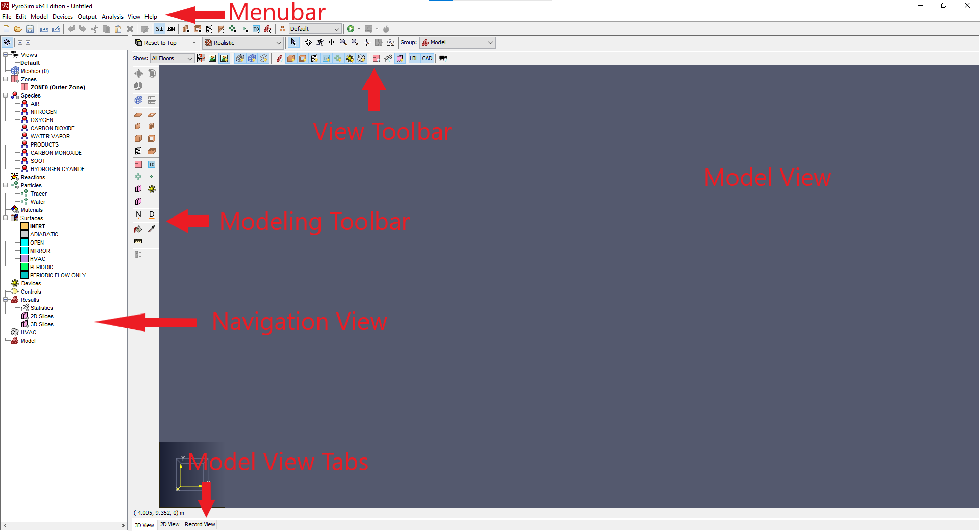
This section will briefly introduce you to each of these elements, many of which will be covered or used later in this tutorial. By the end of this section you should be comfortable moving around in PyroSim.
To get started, open the PyroSim application on your computer.
The Menubar
The Menubar is the collection of menus at the top of the PyroSim interface. Each dropdown menu contains different actions related to different areas of a PyroSim model.

- File Menu
- This menu contains actions related to file operations, like saving, opening, importing, and exporting files.
- Edit Menu
- This menu contains actions related to generic editing operations, like copying, pasting, undoing, and redoing.
- Model Menu
- This menu contains actions related to model manipulation, like creating and editing most objects in the Navigation View.
- Devices Menu
- This menu contains actions specifically related to creating and editing Device objects.
- Output Menu
- This menu contains actions that allow you to edit which data your simulation should output.
- Analysis Menu
- This menu contains actions related to setting up and running your simulation.
- Results
- This menu contains actions that allow you to view and analyzing the results of your simulation.
- View Menu
- This menu contains actions that modify the visualization of your model.
- Help Menu
- This menu contains actions related to technical assistance.
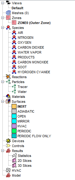
The Navigation View
The Navigation View is the tree view on the left side of the PyroSim interface. This view is a representation of all of the different objects in your model. Right-clicking on an object in this view will open a context menu, providing a list of actions that are available for that specific object. Most objects can be re-arranged in this view by selecting the object and dragging it to the desired position in the Navigation View.
The View Toolbar
The View toolbar is the toolbar located above the Model View in the PyroSim interface. This toolbar allows you to easily control the display settings of the Model View and allows you to change the Model View’s navigation mode. See The 3D View section of the PyroSim User Manual for more information on each specific tool in the View Toolbar.

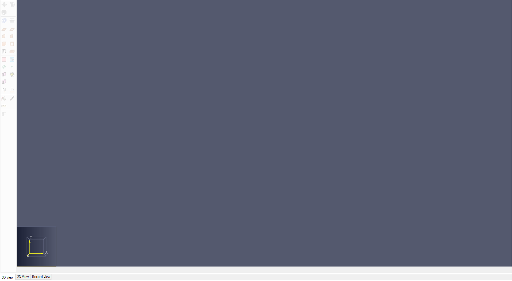
The Model View
The Model View is the main viewport in which you will view your PyroSim model. It provides a 3D, 2D, or FDS Record view of your model, depending on which view tab you have selected.
You can switch between the different model views by clicking on the model view tabs at the bottom of the Model View, shown in Figure 6.
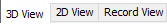
The tabs are as follows:
- 3D View
- Shows the standard 3D perspective representation of your model.
- 2D View
- Shows a 2D orthographic projection of the model on a 2D plane. Will also show a unit grid, which is useful for snapping tools.
- Record View
- Shows the raw FDS input file text generated by the model.This tab, will show the FDS input file that is generated by your model in real-time. You can use this view to verify that everything in your model is being created as expected. This is useful during troubleshooting. You can also add additional FDS records not supported by PyroSim in the Additional Records section at the bottom of that view.
In either the 2D or 3D views, you can easily change the camera orientation to one of the 6 cardinal directions in the View Toolbar, shown in Figure 7.
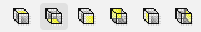
You can also reset the camera position to it’s original position using the Ctrl+R keyboard shortcut.
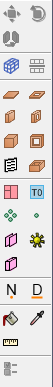
The Modeling Toolbar
The Modeling toolbar, shown in Figure 8, provides quick access to many tools used to create PyroSim models. Clicking on the icon for one of these tools will activate it in the Model View. After using the tool the tool will deactivate. However if you click on the tool’s icon in the Modeling Toolbar twice before using it, a green dot will appear on the icon, which indicates that the tool can be used repeatedly without deactivating. To deactivate a tool after using this mode, press the Esc key.
When using a tool, you can right-click in the Model View to open a context menu. Selecting the Tool Properties option will allow you to configure some tool settings prior to using the tool. These settings control the properties of the objects created by the tool. These object properties can also be edited after the fact.
Conclusion
You should now be familiar with the basics of navigating the PyroSim interface. Don’t worry if you don’t remember everything immediately. As you use PyroSim more, you will begin to memorize where everything is. This section was just intended to give you an introduction.
Model Geometry
The first step to defining any model in PyroSim is to define the model’s geometry. This is done in FDS by defining Obstructions.
An Obstruction is a generic representation of some physical object that 'obstructs' flow in the simulation. FDS is only currently capable of representing Obstructions as rectangular prisms, however PyroSim provides tools that allow you to easily convert more realistic, non-axis aligned geometry into rectilinear obstructions for FDS. These tools will be covered in later tutorials.
PyroSim also offers a number of tools for drawing standard FDS obstructions, which we will use here. These tools create different categories of obstructions, which include the following:
- Slabs
- Slabs are obstructions whose main planar faces are in the XY plane. These are typically used to represent flat surfaces, such as concrete slabs used for building foundations.
- Walls
- Walls are obstructions whose main planar faces are not in the XY plane. These are typically used to represent upright surfaces, such as the walls of a room.
- Blocks
- Blocks are simple obstructions defined by minimum and maximum X,Y,Z points.
FDS also provides a way to subtract geometry called Holes. Holes remove geometry created by Obstructions, and have the same above subcategories (Slabs, Walls, and Blocks) as Obstructions.
Let’s begin making a model by creating some basic geometry.
Creating Geometry
Drawing Slabs
To begin creating geometry for your first model, we’ll draw some slabs to serve as the base of our model. Start by switching to the 2D Top-down view. To do this:
- Click the 2D View tab of the Model View
- Select the Reset to Top option in the View Toolbar.
- Right-click and drag in the Model View to move to the upper-right of the origin.
- Select the
 slab tool in the Modeling Toolbar.
 - Click and drag corner to corner a 5m x 5m slab obstruction.
- Select the slab tool again.
- Right-click with the slab tool selected, then select Tool Properties.
- Set the Z Location of the slab tool to
0.0m. - Draw another 1m x 1m slab in the middle of the slab you previously created.
Now that the slabs are drawn, let’s organize them a little better. To do this:
- Left-click and drag to select the slabs in the Model View.
- With the slabs selected, right-click and select Change Group.
- In the Change Group dialog, select New Subgroup, then name the new subgroup
Slabs. - Double-click the larger, bottom slab in the Navigation View to rename it.
Give it the name
Floor. - Repeat the process for the smaller, top slab, naming it
Fire.
- Select the slab tool again.
- Right-click with the slab tool selected, then select Tool Properties.
- Set the Name to
Ceiling, and Z-location to2.75m, then click Ok. - Draw a slab from corner to corner of the
Floorslab.
- Right-click the
Ceilingslab, and select Hide. This will hide theCeiling, and allow us to see inside the room more clearly, both while creating the model and in PyroSim Results.
Now let’s draw some simple walls.
Drawing Walls
To add some wall obstructions to this model:
- Select the
 wall tool in the Modeling Toolbar.
 - Click on all 4 corners of the
Floorslab to draw walls in your model.
- Like with the slabs, rename the new obstruction to
Walls.
The geometry for the model is almost done. All that is left is to add a hole to the wall to represent a door.
Drawing Holes
To draw a hole in the Walls obstruction in your model:
- Select the
 Wall Hole tool in the Modeling Toolbar.
 - With the tool selected, right-click and select Tool Properties.
- Set the Height to
2.1m. - Set the Wall Thickness to
0.3m. - Click Ok.
- Left-click and drag to draw a 1m wide hole on the left wall..

- Like with the Walls and the Slabs, rename the new Hole object to
Door.
The geometry of your first model is now done! It is probably a good idea to go ahead and save your model so you don’t lose your work in the event of a crash. To do this:
- Click File > Save, or use the Ctrl+S keyboard shortcut.
- Save your model as
my_first_model.psm.
With your model saved, go ahead and check out your geometry in the 3D view to get a better view of the work you just did. To do this:
- Click the 3D View tab in the Model View.
- Right-click to rotate the model in the 3D view, and use the middle-click to move the camera.
As you can see, the model geometry you created is a simple room, with a floor, four walls, a door, and a small block in the middle. This is the final geometry for your model.
You should now be familiar with the basics of creating geometry in PyroSim. The next step to creating your first fire model is to define the characteristics of your fire.
Defining Fire
There are many different configurations and approaches to defining fire and combustion in PyroSim and FDS. Each approach involves many different engineering decisions, which makes it a complex topic in fire modeling. It will take many years of experience to fully understand all of the intricacies involved in this process. Chapter 11: Fire and Thermal Boundary Conditions in the FDS User Guide (McGrattan et al. 2021, 87) has many examples of different, more advanced fire models, and showcases just why this topic can be so complex. We recommend reading that chapter when you feel you are ready for more advanced fire models.
In this tutorial, we will be defining the simplest fire model: The burner fire. A burner fire can be defined by just the following two components:
- Reaction
- A Reaction is one of two main groups of parameters that govern combustion in PyroSim and FDS. It defines a specific set of parameters for a single chemical reaction. This chemical reaction defines how reactant atoms combine to produce Byproducts and heat in your model. The other group of parameters, the Combustion group, defines parameters that apply to all Reactions in the model, as there may be more than one Reaction defined in a single model. Chapter 15: Combustion in the FDS User Guide (McGrattan et al. 2021, 167) goes in to detail on all of the different ways to define these two parameter groups.
- Surface
- A Surface is a set of parameters that defines the set of physical characterstics that make up a solid or opening in a fire model.
The default Surface used by PyroSim and FDS is the
INERTsurface. TheINERTsurface is a surface with a fixed temperature equal to the ambient temperature in the model (more on that later). This is the same light orange surface that was automatically applied to all of the geometry created in Model Geometry section. (McGrattan et al. 2021, 71)
In short, a Reaction is a set of properties defining the chemical behavior of the fire in your model, and a Surface is a set of physical properties that apply to a solid or open surface in your model. If the correct combination of physical properties and reaction characteristics are present in a model, combustion will occur.
We will be keeping things simple for this tutorial, and just use a Reaction from the PyroSim Reaction library and create a basic burner surface.
Adding a Reaction
To add a Reaction from the PyroSim Reaction library:
- Open the Edit Reactions dialog by using the Model > Edit Reactions action, or by double clicking the Reactions entry in the Navigation View.
- In the Edit Reactions dialog, click Add From Library.
- On the right-hand side of the dialog, select the
SFPE WOOD_OAKreaction. - Click the left-hand arrow to add the reaction to the model.
- Click Close.
- Click OK to close the Edit Reactions dialog.
Creating a Surface
We will define a very simple burner surface for this tutorial. You can think of these Surfaces as just ejecting gaseous fuel from the solid object or opening they are applied to. This fuel then ignites, acting as a burner - hence the name "burner surface".
To create a burner surface:
- Open the Edit Surfaces dialog by using the Model > Edit Surfaces action, or by double clicking the Surfaces entry in the Navigation View.
- In the Edit Surfaces dialog, click New.
- In the New Surface dialog, enter the name
Fire, and set the Surface Type toBurner.
The last step in creating this surface is to set the Heat Release Rate for this surface. This is done using the Heat Release Rate Per Area field (HRRPUA). Remember, a Surface is just a set of properties that are applied to a physical object, so some properies, like the Heat Release Rate, will scale with the size of the object. Defining these in terms of the Area makes this scaling uniform and predictable.
The choice of HRR is one of the engineering decisions mentioned previously that takes care and consideration.
For this tutorial, we will be using the data for a Mattress with Box Spring available from the University of Maryland Burning Item Database, which proscribes a maximum Heat Release Rate of 660 kW.
We will be applying our surface to the 1m x 1m Fire obstruction we created earlier, so we can enter a value of 660 for our HRRPUA.
However if you use data like this in the future, you will need to convert this value based on the area of the physical object that you are applying the surface to.
- Enter the value
660in to the HRRPUA field. - Click OK to close the Edit Surfaces dialog.
Applying a Surface to an Obstruction
The last step in defining the fire in our simple model is to apply the Surface properties that we just defined to the top of our Fire obstruction that we created in Model Geometry section.
To do this:
- Double-click the
Fireobstruction in the Navigation view to open it’s Obstruction Properties dialog. - Switch over to the Surfaces tab.
- Select the Multiple radio button.
- Click the Surface* column next to Max Z, then select the
FireSurface that we created earlier.
- Click OK to apply our surface and close the Obstruction Properties dialog.
As you can see in Figure 20, the top surface of the Fire obstruction changes color to the color defined in the Fire Surface properties to indicate that the new surface has been applied.

You have now applied the surface and the fire in your model is defined! There are only two more steps to complete before you are ready to run your simulation.
Meshes
The next step to create your fire model is defining a mesh. A Mesh defines the 3-dimensional computational domain that FDS uses to simulate your model. FDS uses the Mesh to break your model up in to distinct cells, which then each are used in a series of calculations. As a general rule, as you decrease the cell size the accuracy of the FDS simulation to the inputs you have provided increases. However, this will also increase the amount of time it takes to complete the simulation. There are exceptions to this rule, however we will not cover those here.
This tradeoff makes mesh definition one of the more important engineering choices you will make when defining a model. You will need to select a mesh size that balances the simulation time with the accuracy of the model.
For this tutorial, we will keep things simple. Because this is such a simple model, we will create a uniform mesh and not worry too much about the balancing act here. This model is so small that simulation time will be short even with a very fine mesh, and accuracy is not a concern in a tutorial.
Creating a Mesh
To create a Mesh:
- Open the Edit Meshes dialog by using the Model > Edit Meshes action, or double-clicking the Meshes entry in the Navigation View.
- In the Edit Meshes dialog, click New.
- In the New Mesh dialog, provide the name
My Mesh, then click OK.
By default, PyroSim will make a mesh using the detected maximum and minimum geometric bounds of your model. In most scenarios with Computational Fluid Dynamics tools such as FDS, you will want a physical gap between the edge of your model and the boundary of the computational domain to allow for any boundary layer development. We will create that gap here.
- In the Edit Meshes dialog, select
My Mesh. - Set Min X to
-3.0. - Set Max X to
8.0. - Set Min Y to
-3.0. - Set Max Y to
8.0. - Set Min Z to
-0.2. - Set Max Z to
8.2. - Click Apply.
The Mesh is now expanded slightly off of the boundaries of our model. Note that the exception here is the Min Z of the mesh. This is the bottom of our Mesh, which for this model represents the ground. Because we are not interested in the effect under the ground, we set this value to that of the minimum Z of our model exactly.
Now that the boundaries of the Mesh are set, the last step is to set the cell size.
The current cell size for this Mesh is 0.44m x 0.44m x 0.42m.
For each dimension, this represents the overall length of the mesh divided by the number of cells in that direction.
Using the X dimension as an example, 0.44m is the result of dividing the X range, 11m, by the number of cells in the X direction, 25.
To change the cell size, we will need to change the number of cells in each dimension. To do this:
- In the Edit Meshes dialog, select
My Mesh. - Set X Cells to
50. - Set Y Cells to
50. - Set Z Cells to
40. - Click OK to apply your changes and close the Edit Meshes dialog.
Notice what this does to the mesh.
The cell size has changed from 0.44m x 0.44m x 0.42m to 0.22m x 0.22m x 0.21m.
Each dimension of the cell has been cut in half.
However, note the change in the Number of cells for mesh.
It increased eightfold, from 12,500 to 100,000.
This change will increase the accuracy of the simulation, but will also increase the computational cost.
Boundary Conditions
One of the final steps before running your model is telling FDS what should happen at the boundary of your mesh. Should fluids flow freely through the boundary? Should it be treated as a solid surface? Should fluids wrap back around to the other side of the domain?
These properties are defined by boundary conditions. Thankfully, FDS provides a set of pre-defined boundary conditions in the form of Surfaces. If you remember, Surfaces are just a set of physical properties that apply to a solid object or opening. The same principle applies to mesh boundaries.
We will just define a simple OPEN boundary condition on this Mesh. This condition will tell FDS to treat the boundary as open to the atmosphere. Fluids from inside the model will be able to flow out of the boundary, and ambient air will be able to flow in.
Defining Boundary Conditions
PyroSim provides and easy way to create these conditions. To define the boundary conditions of your vent:
- Right-click the
My Meshobject in the Navigation View to open a context menu. - Select the Open Mesh Boundaries action.
You should now see a Mesh Boundary Vents group in the Model portion of the Navigation View.
There should also be a subgroup called Vents for My Mesh.
This group contains 6 Vents created that define the boundary conditions at each boundary of My Mesh.
A Vent is a new object for us, however it should be a familiar concept to grasp.
Vents provide a way for us to apply a Surface (a set of physical properties) to a 2D plane. The Vents that were created by the Open Mesh Boundaries action were created at the boundaries of our mesh, and use the default OPEN surface. If you want to change the boundary conditions of your model, you would simply need to change the surface applied to these Vents.
There are some slight caveats to Vents however. Vents must have a backing - meaning, they must have some physical object or opening to apply to. Because of this, Vents must be made on top of an Obstruction, or on a mesh Boundary.
With the boundary conditions of the Mesh set, it is time to set up and run the simulation!
Simulation
We will first set up some simple parameters for the simulation, then run it and view the results.
Defining Simulation Parameters
There are many Simulation-wide parameters that you can define in FDS. These can affect things such as time, radiation calculations, particle lifespan, and more. For the purpose of this tutorial, we will just define two properties:
- End Time
- The simulation End Time is how long we want the simulation to run for, in simulation time.
In PyroSim, the default value is
1.0E-3sand will almost always need to be thoughtfully updated by the user for proper simulation. - Ambient Temperature
- The ambient temperature defines the initial temperature of everything at the start of the simulation.
The default value is
20°C.
We will modify these values. To do so:
- Open the Simulation Parameters dialog by using the Analysis > Simulation Parameters action.
- On the Time tab, set the End Time to
60s. - On the Environment tab, check the box next to Ambient Temperature, then set the field to
22°C. - Click OK to apply these changes.
Running the Simulation
There are a couple of different execution options available for running a simulation, the details of which can be read about in Relevant section of the PyroSim User Manual. For this tutorial, we will be running the simulation using a single process. To do this:
- Click the dropdown next to the
 icon in the top toolbar.
 - Select Run FDS
This will bring up the FDS Simulation dialog, and will start your simulation.
Therer are a few elements of this dialog to note:
- Progress
- This shows the total progress of the simulation in simulation time.
Note how this is a time out of the
60sthat you set as the End Time of the simulation. - Time Elapsed
- This shows how long the simulation has been running in real time.
- Time Remaining
- This shows an estimate of how much longer the simulation will take to complete, in real time.
The simulation should take a few minutes. When it is complete, the PyroSim Results viewer should automatically open and load the results of your simulation.
Results
Congratulations! You have now run your first ever fire model with PyroSim and FDS. Now it is time to take a look at the results of the simulation.
Viewing the Results
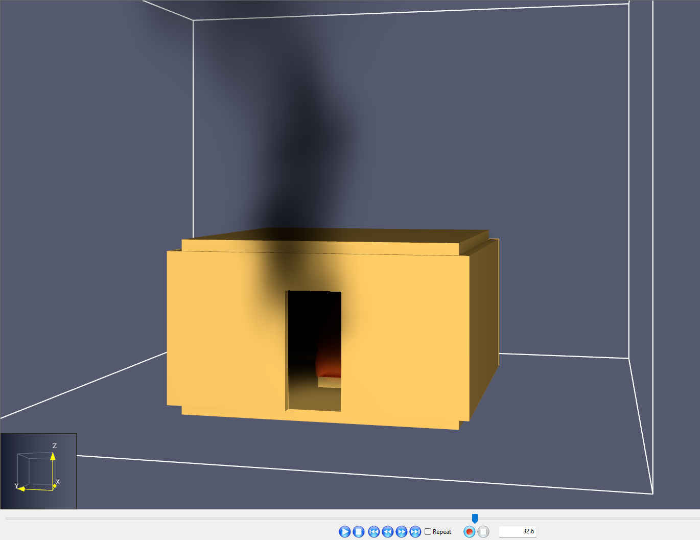
After your simulation finished, the PyroSim Results viewer should have opened and loaded the simulation results. The results viewer reads all of the graphical data files created by FDS provides useful visualizations for your analysis.
To view the results of the model:
- In the PyroSim Results window, double-click the 3D Smoke entry.
- Click the
 Play button to begin the 3D results playback.
- In the Navigation panel, select the dropdown arrow for the Scene Geometry Group.
- In Scene Geometry, select the dropdown arrow for PyroSim Geometry.
- In PyroSim Geometry, select the dropdown arrow for Model.
- In Model, right-click Ceiling and click Hide to hide the
Ceilingslab. - Rotate the model using the right-mouse button to get different views of the results.
With the ceiling hidden it is easier to see the simulated fire. Watch the playback of the fire as it develops over the 60 seconds of simulation time that you specified.
Saving a Results Visualization
- Save the current Results Visualization as
view-no-ceiling.smvv.
This is just the most basic of 3D results available in PyroSim Results. We will cover more advanced data output and visualizations in later tutorials.
Conclusion
That’s it! You are done with your first fire model in PyroSim. You should now be familiar with how to navigate the PyroSim interface, create basic model geometry, define a fire and a mesh, run the simulation, and view the results. But most importantly, you should now be familiar with the basic concepts of fire modeling in PyroSim and FDS. You will build on these concepts in later tutorials, as well as in your own personal experience making fire models.
You can download the complete model created in this tutorial here: Your First Fire
To continue building your skillset, check out the recommended tutorial linked below. It will teach you how to add additional data outputs to this model.
Please contact support@thunderheadeng.com with any questions or feedback regarding our products or documentation.
Bibliography
McGrattan, Kevin, Simo Hostikka, Randall McDermott, Jason Floyd, and Marcos Vanella. 2021. Fire Dynamics Simulator User’s Guide, NIST Special Publication 1019. Sixth Edition. National Institute of Standards and Technology, Gaithersburg, Maryland, USA: NIST.
Related Tutorials
(Legacy) Tutorial to experience the fundamental features of PyroSim
Video tutorial demonstrating how to fix geometry problems related to DWG importation.
Tutorial Demonstrating how to model pressure leakage using Pyrosim
This tutorial will walk you through adding some basic fire protection systems to your PyroSim model.
This tutorial will walk you through using external 3D CAD geometry in your PyroSim model.
This tutorial will walk you through adding and layering materials, allowing for more complex heat transfer in your PyroSim model.
Video tutorial demonstrating how to avoid creating unwanted gaps in the geometry of a Pathfinder model.
In this tutorial we show how to fix three problems that can occur when BIM (Building Information Modeling) or CAD (Computer-Aided Design) models into Pathfinder.