Overview
This tutorial is specifically designed for individuals who are new to using Pathfinder. In this course, we will provide a step-by-step demonstration of how to create a basic evacuation simulation in Pathfinder and provide an explanation of some of the underlying concepts. By the end of this tutorial you will have gained proficiency in navigating the Pathfinder egress software interface. We demonstrate viewing a model, building a model, running a simulation, and interpreting the results.
Before Starting
- Download and install the latest version of Pathfinder from the Pathfinder download page.
- If you have not already, sign up for a free 30-day trial license or purchase a license.
- Visit the latest version of the Pathfinder User Manual for reference throughout this tutorial.
- Download the Pathfinder Fundamentals zip
What is Pathfinder?
Welcome to the very first tutorial on creating models in Pathfinder. Before jumping into things, it is important to briefly go over what Pathfinder is.
Pathfinder is a flexible movement simulator that uses steering behaviors to model occupant motion. The program has grown from an agent-based fire egress software to a pedestrian circulation modeling tool for a wide range of scenarios. It consists of three modules: a 3D modeling interface, robust simulator, and an optimized 3D results analysis tool.
Pathfinder provides two primary options for occupant motion; SFPE mode and Steering mode.
SFPE mode
This mode implements the concepts in the SFPE Handbook of Fire Protection Engineering. This is a flow model, where walking speeds are determined by Occupant density within each Room, and flow through doors is controlled by door width. This model is also known as the "hydraulic model of emergency egress". (SFPE Handbook)
Steering mode
This mode is based on the idea of inverse steering behaviors. Steering behaviors were first presented in Craig Reinolds' paper "Steering Behaviors For Autonomous Characters" (Reinolds 1999) and later refined into inverse steering behaviors in a paper by Heni Ben Amor et al. (Amor et al. 2006). Pathfinder’s steering mode allows more complex behavior to naturally emerge as a byproduct of the movement algorithms, eliminating the need for explicit door queues and density calculations.
The simulation described in Create a New Model will use Steering mode. You can freely switch between the two modes within the Pathfinder user interface and compare answers.
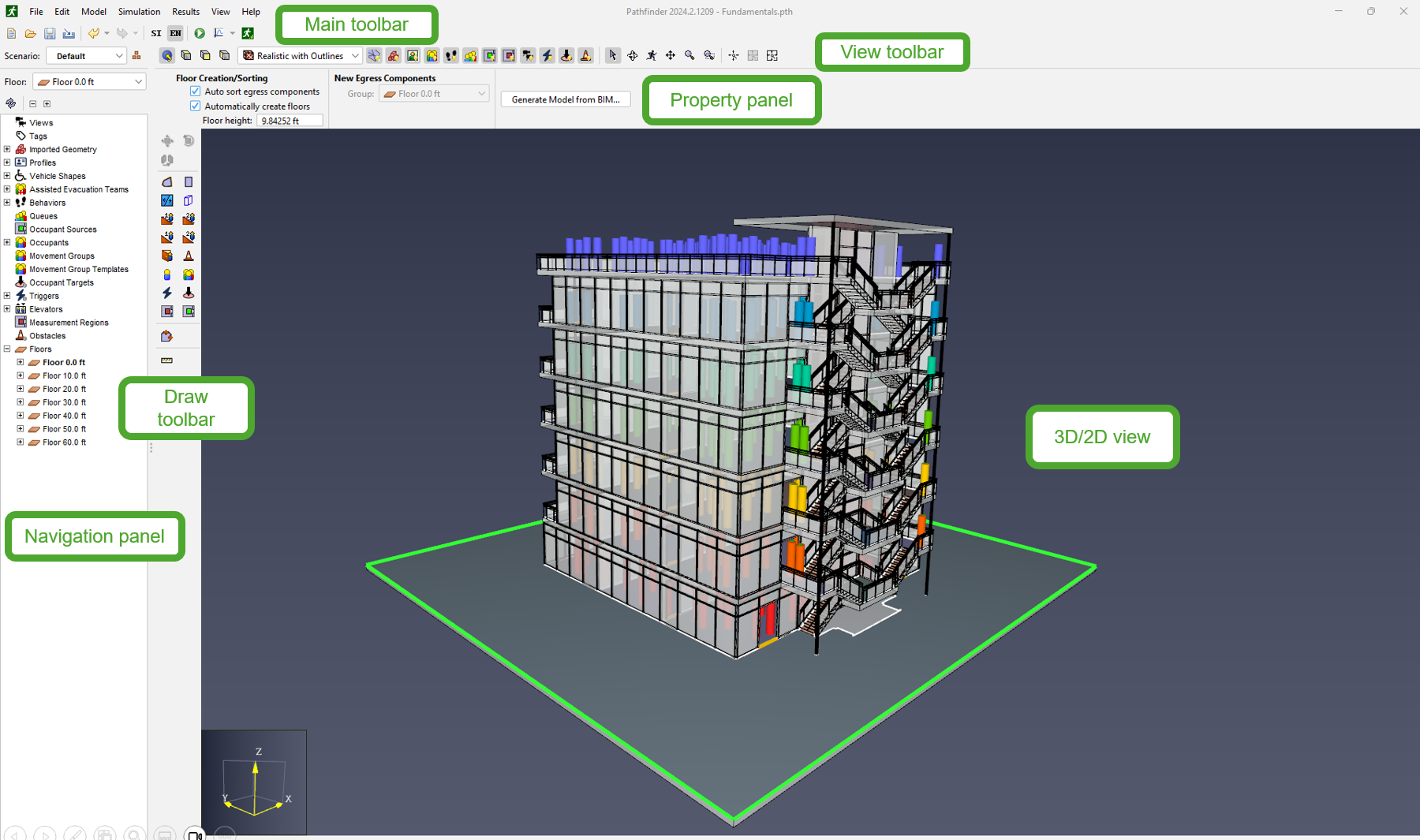
Explore the Interface
In this section and its sub-sections, you will use an existing model to learn the basic operations of Pathfinder.
To explore the Pathfinder interface
- Download the zip folder in Before Starting.
- Right-click
pathfinder-fundamentals.zipand click Extract All. - From the extracted folder, open
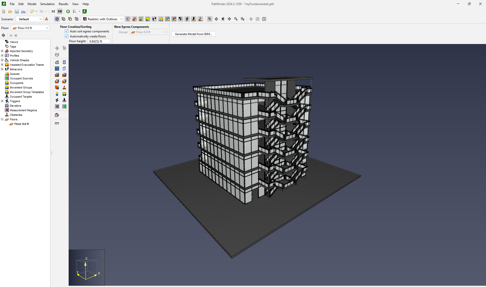
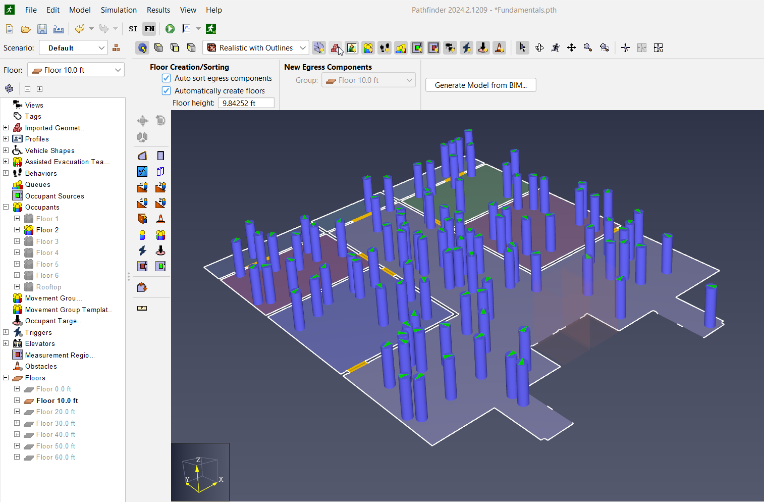
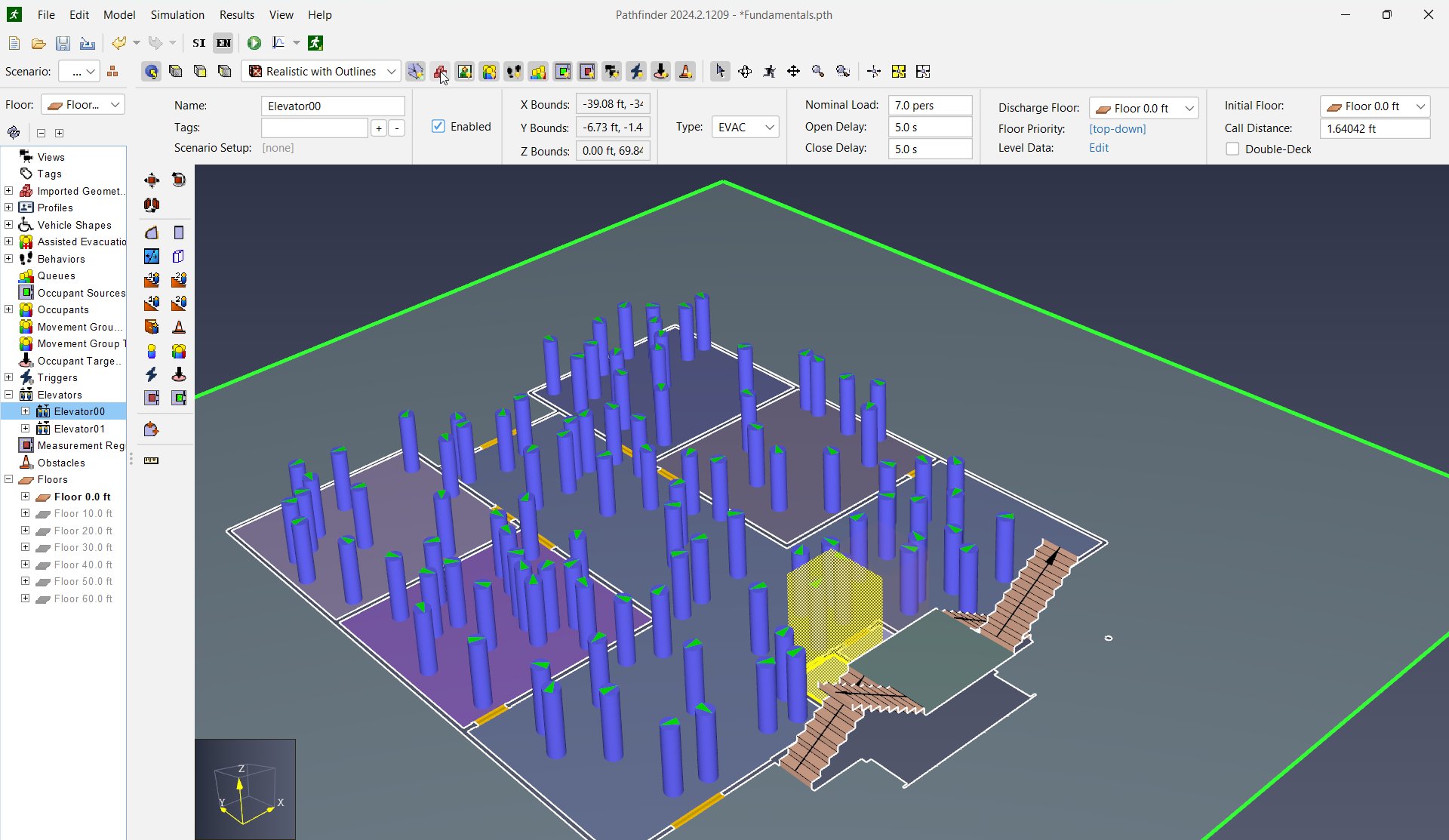
Fundamentals.pthto launch Pathfinder with that model. - Review the interface elements as shown in Figure 1. These will be referred to often throughout Pathfinder tutorials.
View a Model
This section will demonstrate some of the basic options to control your view of the model. Select the various options in the View toolbar and manipulate the 3D view.
To view a model
On the View toolbar, click
 Switch to the Perspective View.
- On the View toolbar, click
 3D Orbit Navigation.
 - Drag the mouse to rotate the camera.
- Hold down SHIFT while dragging the mouse to pan the camera.
- Rotate the mouse wheel, or hold down ALT while dragging the mouse, to zoom the camera.
- Hold down the scroll wheel to move the camera.
On the View toolbar, click
 Switch to the Top View.
- On the View toolbar, click
 Select/Edit Objects.
 - Hold down the left mouse button and drag to select objects.
- Hold down the right mouse button and drag to pan the camera.
- Rotate the mouse wheel to zoom the camera.
You have successfully learned the basics of viewing a model.
Manage Objects
In this section, you will learn how to use the Navigation panel to view, hide, and select objects.
To manage Objects
- On the View toolbar, click Switch to the Perspective View.
- On the Navigation panel, right-click
 Floor 0.0 ft and click Set as active floor to isolate it.
 - On the Navigation panel, right-click Floor 10.0 ft and click Show to add its objects to the current view.
On the 3D view, right-click any object and click Hide to remove it from the current view.
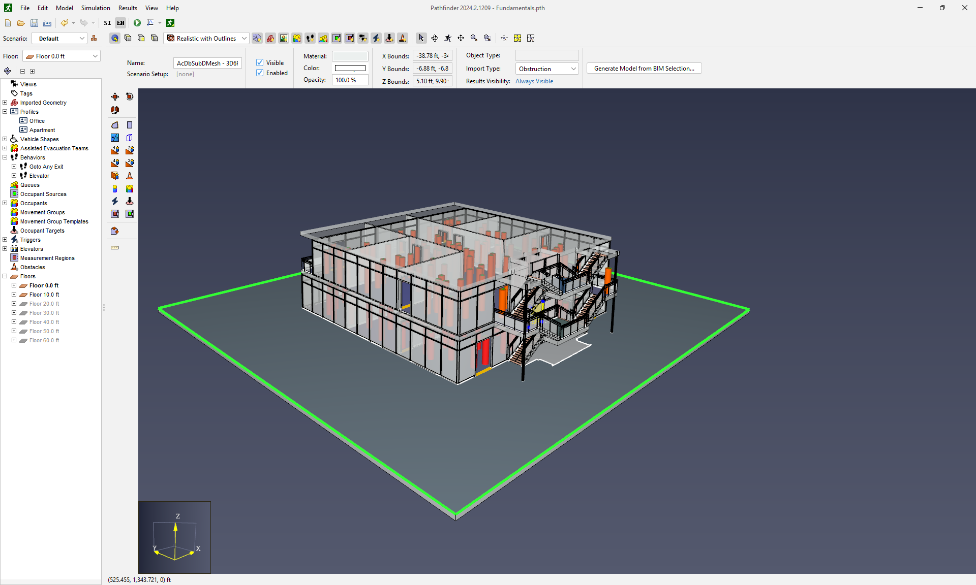
Figure 3. Pathfinder Object Selection. Click to enlarge. - On the 3D view, right-click any empty space and click Show All to bring all objects back into the current view.
- On the Navigation panel, select
 Auto Expand Selection.
 - On the 3D view, click any object. The Navigation panel expands and highlights the matching object in the list.
You have successfully learned the basics of managing objects in the Navigation panel.
Run a Simulation
In this section, you will learn how to initiate a simulation and analyze the results.
To run a simulation
On the Main toolbar, click Run Simulation. The Run Simulation dialog box should open automatically and begin displaying progress.
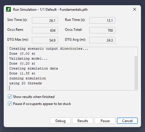
Figure 4. The Run Simulation Dialog, while a Pathfinder simulation is run for Fundamentals.pth - The 3D Results program window can be set to appear upon completion as in Figure 4.
If not, open the
 3D Results program.
Inspect results
To inspect results
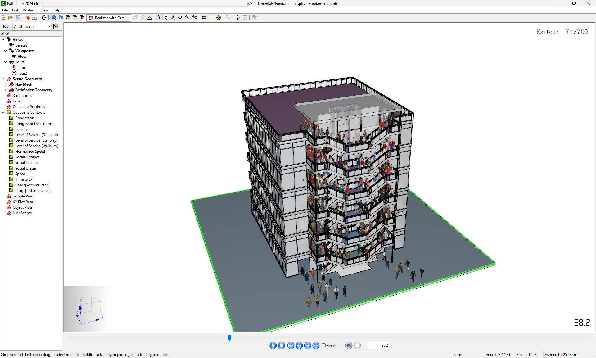
- In View → Occupant Display menu, click Show as People. Occupants can be displayed in several ways, with all display options found in this menu.
- On the Results window, click
 Play.
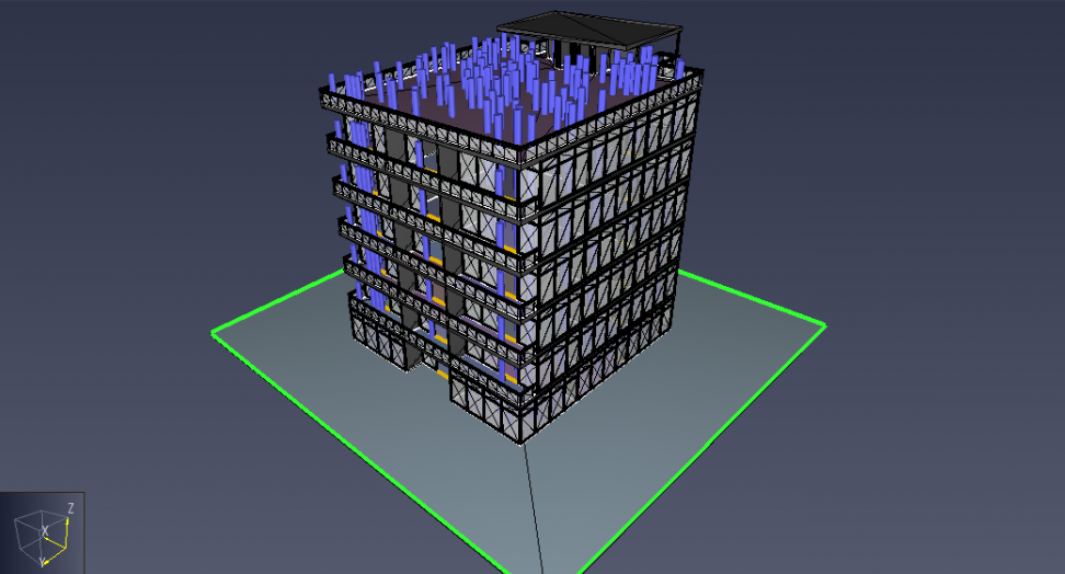
The simulation will play until all occupants have exited the model, and should appear similar to Figure 5.
Play.
The simulation will play until all occupants have exited the model, and should appear similar to Figure 5. - On the Playback toolbar, click
 Increase Speed to play the results two times faster than real time.
 - Close the Results program and the Run Simulation dialog box.
You have successfully learned the basics of running a simulation.
Keyboard Shortcuts
By default, Pathfinder uses a variety of keyboard shortcuts that are standard to Windows and Java applications. To accelerate model creation, Keyboard Shortcuts can be added or changed in a variety of ways.
Create a New Model
In this section and its subsections, you will create a complete model which can be used in a simulation. The steps in this section demonstrate the fundamental parts of building a model in Pathfinder.
To create a new model
- On the Main toolbar, click
 New Model.
If prompted by the Save Changes dialog box, click No.
New Model.
If prompted by the Save Changes dialog box, click No. - On the Main toolbar, select
 Show values in EN units.
 - On the Main toolbar, click
 Save model.
 - Create a new folder named
Getting Started, and name the filemyFundamentals.pth.
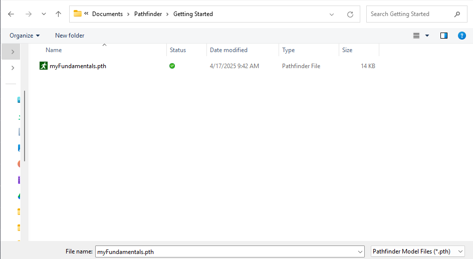
You have successfully created and configured a new model.
Import Geometry
In this section, you will import geometry from a model created in another CAD application. This will allow you to draw the navigation mesh faster than starting from a blank file.
To import geometry
- On the Main toolbar and click
 Import File.
 - Navigate to the
Pathfinder-Fundamentalsfolder extracted frompathfinder-fundamentals.zipand openpathfinder-fundamentals.dwg. - On the Import dialog box, select Into the current model.
- Select mm as the file’s length unit and click Next.
- Click Calculate to view information about the model with the selected units to ensure that the selected units are correct.
The Model Height for this file is
70.0 ftand is confirmed in this dialog box. - Click Next.
- Use the default import settings and click Next.
- Click Finish to import the file.
You have successfully imported the model.
Extract Floor
In this section, you will create a navigation mesh over the imported floor so that rooms, doors, and occupants can be created.
To extract the first Floor
- On the Draw toolbar, click
 Extract Floor from Imported Geometry.
 - On the 3D view, click anywhere on the surface of the first floor.
- On the View toolbar, clear
 Show Imported Geometry.
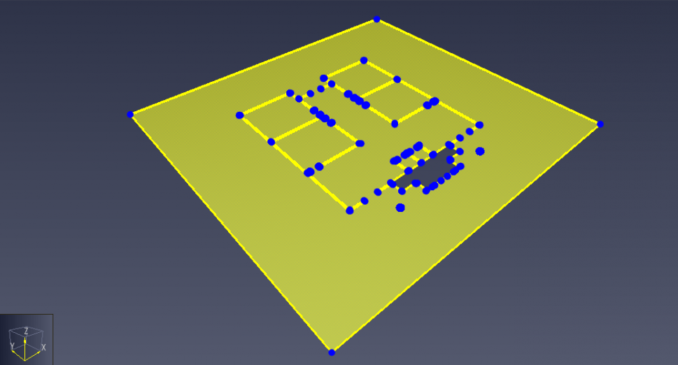
You have successfully extracted the first floor.
Create Doors
In this section, you will create doors over the imported geometry so that rooms are connected and occupants can make decisions about where to go.
To create Doors
On the Draw toolbar, double-click
 Add a New Door.
- On the property panel in the Max Width box, type
60 in. On the property panel in the Max Depth box, type
10 in. Press TAB to set the value.On the 3D view, zoom in on a particular doorway. Point to the center of the doorway so that the door is previewed and click on the doorway.
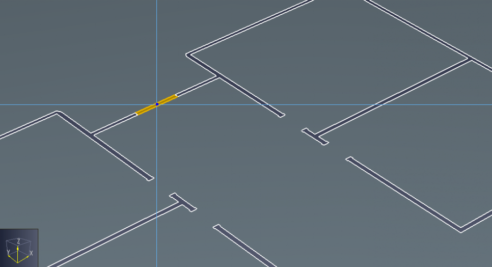
Figure 9. The door will preview when you have placed the pointer in an appropriate doorway. - Repeat the previous step for each of the 11 doorways. The individual rooms of the first floor are automatically created as the doors are added.
On the 3D view, point to a corner of the outer grounds. Drag to an adjacent corner to make that whole edge of the floor plate an exit.
- Repeat the previous step for the other three sides of the outer grounds.
- Press ESC once all doors have been created to close the door tool.
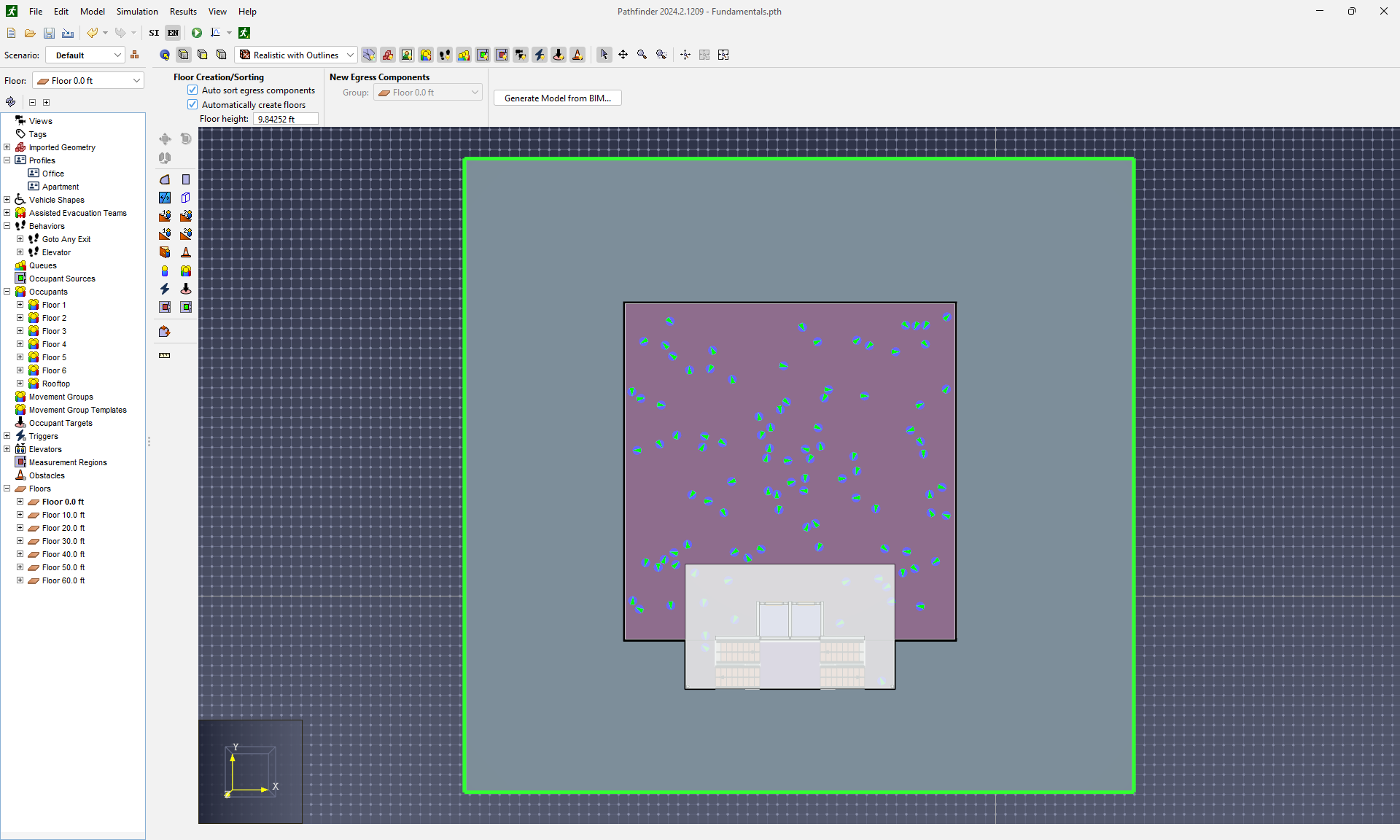
Create Occupants
In this section, you will add occupants to the rooms.
To add Occupants
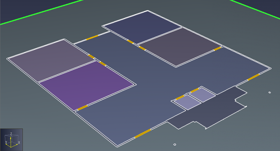
- On the Navigation panel, select Floor 0.0 ft.
On the 3D view, hold down Ctrl and click the elevator rooms and the outdoor floor to unselect.
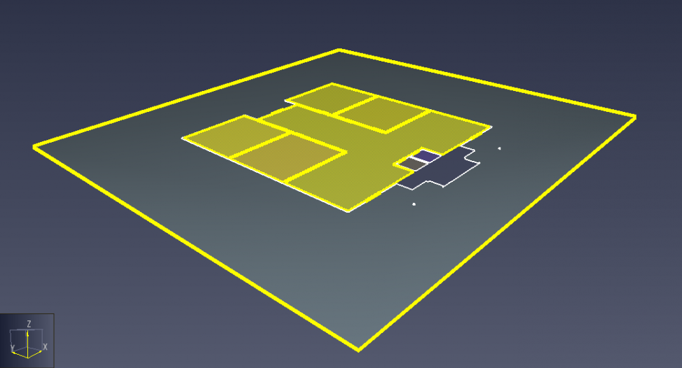
Figure 11. Your selection should include all of the main rooms. - On the 3D view, right-click any selected area and click Add Occupants.
In the Add Occupants dialog box, enter "Floor 1" in the Group Name and then in the By Number box, type
100and click OK.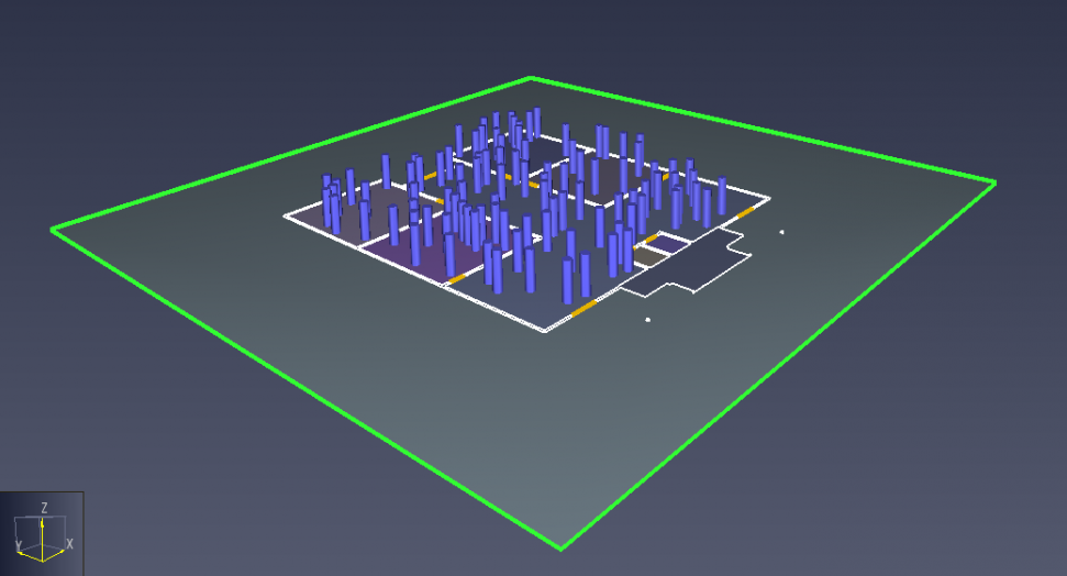
Figure 12. 100 agents distributed between the selected rooms.
With occupants created on the first floor, you can run a test simulation as desired.
Add Floors
In this section and its subsections, you will complete the rest of the geometry by adding components for multi-floor models.
To add Floors
- At the top of the Navigation panel, in the Floor list dropdown, select Add New.
- On the New Floor dialog box in the Enter Floor Location box, type
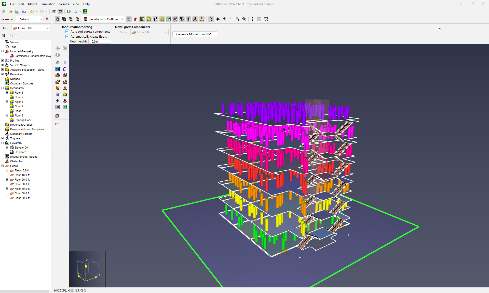
10 ftand leave the boxresort existing components to new levelselected. Click OK. - Repeat the previous steps for each floor until you have created Floor 60.0 ft.
- On the View toolbar, select Show Imported Geometry.
At the top of the Navigation panel, in the Floor list dropdown box, select
Floor 10.0 ft.On the 3D view, right-click the Floor 10.0 ft ceiling and click Hide.
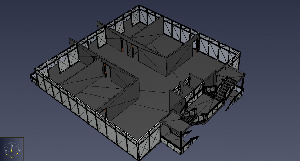
Figure 13. Floor 10.0 ft with the ceiling hidden so the floor and walls of the imported geometry are visible. - On the Draw toolbar, click Extract Floor from Imported Geometry.
- On the 3D view, click anywhere on Floor 10.0 ft.
- On the View toolbar, clear Show Imported Geometry.
- Hide the imported geometry and then add eight doors, similar to Floor 0.0 ft in Create Occupants, excluding the elevator shaft doors.
- On the Navigation panel, right-click Floor 10.0 ft and click Add Occupants.
- In the Add Occupants dialog box, enter "Floor 2" for the Group Name and in the By Number box, type
100and click OK.
Copy Floors and Occupants
In this section, you will copy objects from the second floor to other floors of the model. This saves time because the middle floors are identical.
To copy Floors and Occupants
- On the Navigation panel, expand the Occupants list.
- On the Navigation panel, select Floor 10.0 ft.
Hold down the control key and select the "Floor 2" occupant group.
- On the Draw toolbar, click
 Copy/Move Objects.
 - On the property panel, select Copy Mode.
- On the property panel in the Copies box, type
4. Leave theRandomize parameters of object copiesbox selected. - On the property panel in the Move Z box, type
10 ft. Keep the cursor out of the 3D View Window to avoid manually overriding the Move Z value. - On the property panel, click Copy/Move. Keep the cursor out of the 3D View Window to avoid manually overriding the Move Z value.
- On the Navigation panel, select all copied occupant groups. Right click any of the selected items and click Rename… to open the Rename dialog.
- In the Rename dialog, select the Rename with Template checkbox and in the box Enter the new name: enter Floor ${local_index}.
- Click OK to quickly rename all items.
Add Rooftop Floor
The top floor is different than the middle floors, so we need to extract it separately.
To add a rooftop floor
- On the Navigation panel, right-click Floors and click Show.
- On the View toolbar, select Show Imported Geometry.
- On the Draw toolbar, click Extract Floor from Imported Geometry.
- On the 3D view, click anywhere on the rooftop floor.
- On the Navigation panel, right-click Floor 60.0 ft and click Add Occupants.
- On the Add Occupants dialog box, name the group 'Rooftop Floor' and in the By Number box, type
100and click OK.
Create Landing and Stairs
In this section, you will create a navigation mesh over the imported stairs so that occupants can traverse between floors.
To create a navigation mesh
- On the Navigation panel in the Floor list, select Show All.
- On the View toolbar, select Show Imported Geometry.
- On the Draw toolbar, click Extract Floor from Imported Geometry
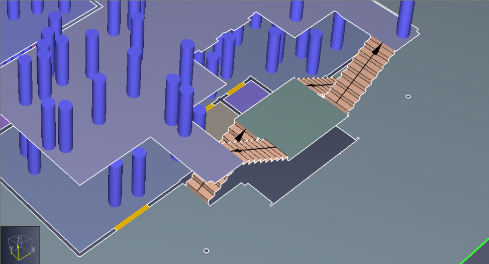
On the 3D view, click anywhere on the landing connected to the four stairs.
Figure 15. The landing should connect to the four stairs. - On the View toolbar, clear Show Imported Geometry.
- On the Draw toolbar, click
 Create stairs between two edges by choosing a point on each.
 For one of the four stairs connected to the bottom landing, click a point along the bottom and top edge to create the stairs.
- Repeat the previous steps for the other three stairs connected to the bottom landing.
Copy Landings and Stairs
Again we will use the copy feature within Pathfinder to save time, while duplicating repeating geometry in the vertical direction.
To copy Landings and Stairs
- On the 3D view, hold down Ctrl while clicking the four stairs and the landing.
- On the Draw toolbar, click Copy/Move Objects.
- On the property panel, select Copy Mode.
- On the property panel in the Copies box, type
5. - On the property panel in the Move Z box, type
10 ft. - On the property panel, click Copy/Move.
Create Elevators
In this section, you will create elevators. This will complete the model’s geometry.
To create Elevators
- On the Navigation panel in the Floor list, select Floor 0.0 ft.
- On the View toolbar, clear Show Imported Geometry.
- On the 3D view, right-click one of the two elevator rooms and click Create Elevator.
- On the New Elevator dialog box, click OK.
- Repeat steps 3-4 for the other elevator room.
Modify Occupants
In this section and its subsections, you will customize the way that the occupants interact with the model. This allows for greater customization and accuracy in various scenarios.
To modify Occupants
- On the Navigation panel in the Floor list, select Show All.
- Expand the
 Occupants list.
 - On the Navigation panel, select the Floor 1 occupant group.
- On the property panel, select Color, and click the color box.
- On the Color dialog box in the Color Code box, type
FF2222, and click OK. You can also use the Palette tab on the Color dialog box to select predefined colors instead of typing in a color code. - Repeat the previous steps for Floor 2 through Floor 6 occupant groups to make them each different colors.
Create Behaviors
In this section, you will create a behavior for occupants to use the elevator. During evacuation, it has been observed that occupants on lower floors are more likely to use stairs than occupants on higher floors. We will use behaviors to assign different probabilities of stair usage by floor. In general, behaviors define a list of goals that occupants will accomplish before they exit or go to a refuge room.
To create Behaviors
- On the Navigation panel, right-click
 Behaviors and click New Behavior.
 - On the New Behavior dialog box in the Name box, type Goto Elevator and click OK.
- On the property panel, select
 Goto Elevators from the Add Action list.
 - On the property panel, click Create.
- On the Navigation panel, right-click the Floor 3 occupant group and click Properties.
- On the Edit Selected Occupants dialog box, click the Behavior link.
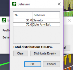
- On the Behavior dialog box, enter
10next to the Elevator behavior and enter90next to the Goto Any Exit behavior. - Click OK on both dialog boxes.
- Repeat the previous steps for the Floor 4 and Floor 5 occupant groups.
Use
20and80as the Elevator and Goto Any Exit distribution percentages. - Repeat the previous steps for the Floor 6 and Rooftop occupant groups.
Use
30and70as the Elevator and Goto Any Exit distribution percentages.
Create Profiles
In this section you will create occupant profiles so that each individual occupant has different characteristics.
To create Profiles
- On the Navigation panel, right-click
 Profiles and click Add a Profile.
- On the New Profile dialog box in the Name box, type Office and click OK. The Edit Profiles dialog box should open.
- On the Edit Profiles dialog box on the 3D Model box, click the list of models.
- On the 3D Model dialog box, select models that represent a typical office environment and click OK.
- On the Edit Profiles dialog box on the Characteristics tab in the Speed list, select Uniform.
- In the Speed list, click Edit to open the Uniform Distribution dialog box.
- On the Uniform Distribution dialog box in the Min box, type
2.0. - On the Uniform Distribution dialog box in the Max box, type
4.3and click OK.
- On the Edit Profiles dialog box, click Apply.
- On the Edit Profiles dialog box, click New….
- Repeat previous steps for an Apartment profile.
Use casually dressed models.
Use a uniform speed of
[3.0 ft/s, 5.3 ft/s]and click Apply. - On the Edit Profiles dialog box, select Default and click Delete.
- On the Remove dialog box, click Yes.
- On the Profile in Use dialog box on the Replace with box, select Office and click OK.
- On the Edit Profiles dialog box, click OK.
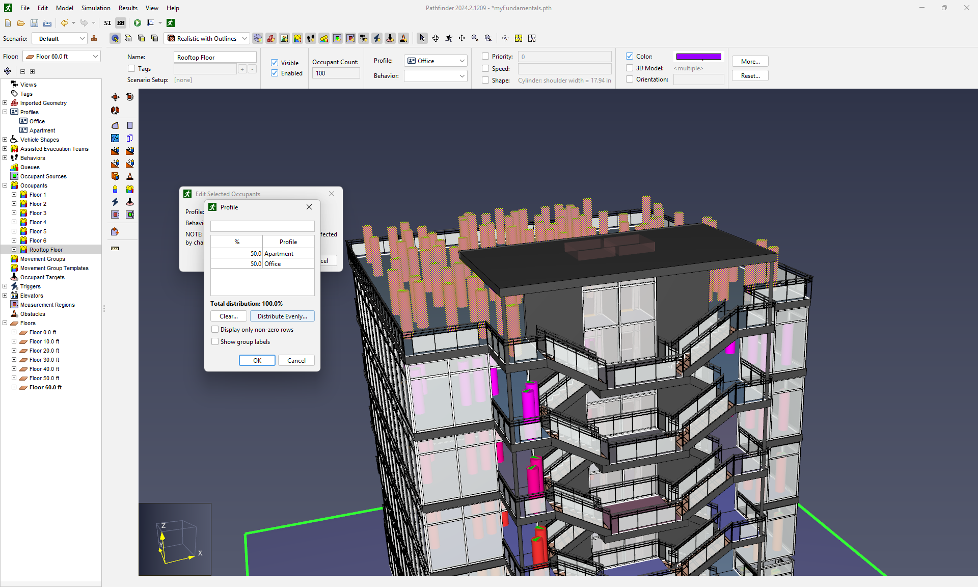
- On the Navigation panel, right-click the Rooftop occupant group and click Properties.
- On the Edit Selected Occupants dialog box, click the Profile link.
- On the Profile dialog box in the Rooftop box, click Distribute Evenly and click OK.
- On the Edit Selected Occupants dialog box, click OK.
- Repeat previous steps for Floor 5 - Floor 6 and assign 100% of the occupants the Apartment profile.
Run the simulation
To run the simulator program
- On the Main toolbar, click
 Run Simulation.
De-select the
Run Simulation.
De-select the Open results on finishbox. - Click OK to close the Run Simulation dialog box when the simulation is finished running.
Analyze Results
This section and its subsections explore the post-processing options in Pathfinder and 3D Results.
Analyze Results in Pathfinder
To analyze results in the Pathfinder modeling interface
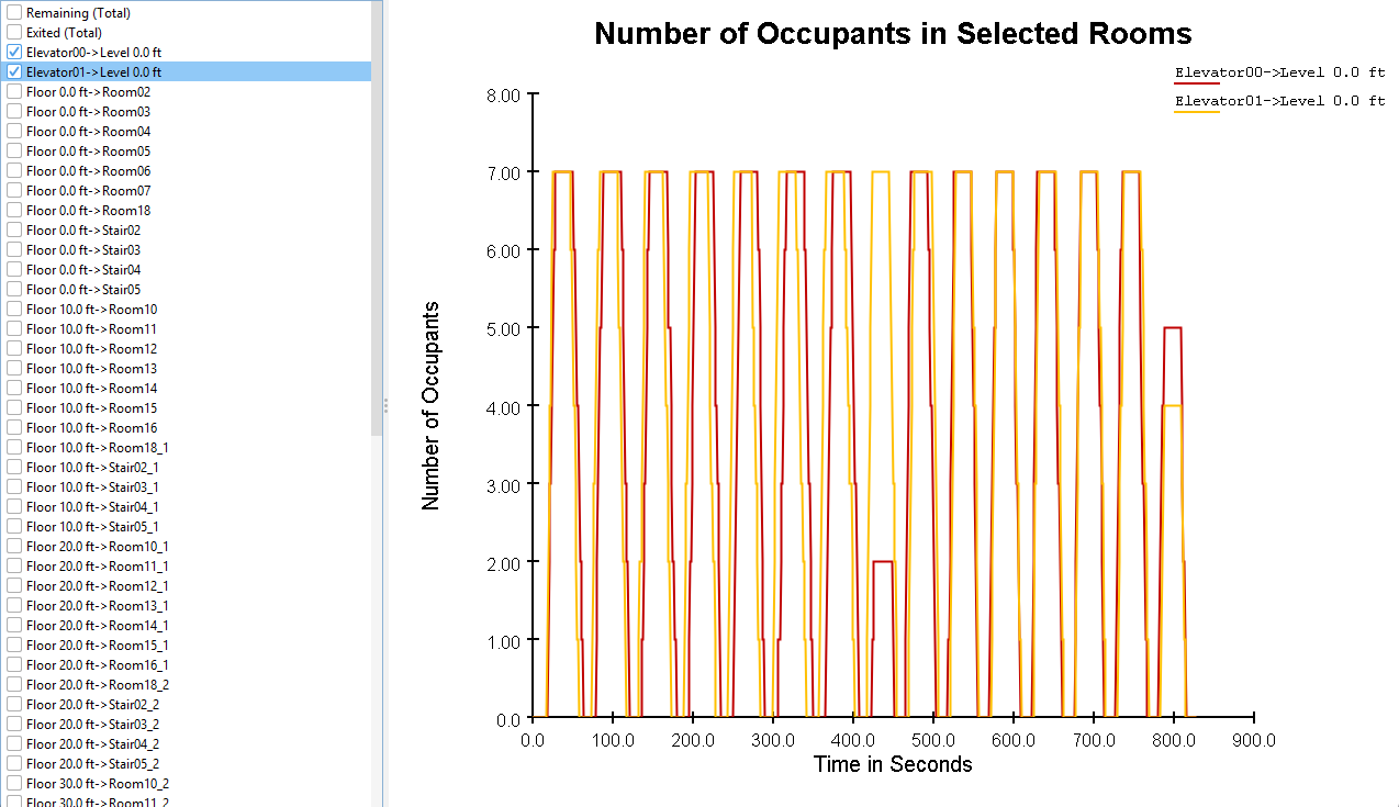
- On the Main toolbar, click
 View Room Usage.
 - On the Occupant Counts window on the Navigation panel, clear all and select Elevator00→Level 0.0 ft and Elevator01→Level 0.0 ft. This is the usage of the elevators, as in Figure 22.
- Close the Occupant Counts window.
You have successfully compiled the simulation and viewed the first results option in Pathfinder. For the remainder of the analysis, switch to Results.
Analyze Results in 3D Results
In this section, you will load contour plot data and modify the output display.
The steps are performed in the 3D results visualization software that accompanies Pathfinder. Visualization data for the model will be saved to the MyFundamentals results folder in MyFundamentals.pfrv. Results visualization files are useful for saving multiple sets of visualization data for the same results data.
Warning:
These instructions are for Pathfinder 2018.3 and later; we create the camera tour in the ![]() 3D Results program.
In earlier versions, the camera tour could be created and saved in the Pathfinder modeling interface as part of Views.
Tours created in Pathfinder 2018.3 and earlier remain accessible in 3D Results as view-only camera tours.
3D Results program.
In earlier versions, the camera tour could be created and saved in the Pathfinder modeling interface as part of Views.
Tours created in Pathfinder 2018.3 and earlier remain accessible in 3D Results as view-only camera tours.
Modify Visualization Contours
Adding Feathering to the plot will hide some of the noise and clean up the visualization.
To add feathering
- On the Main toolbar, click View 3D Results.
- On the 3D Results window on the Navigation panel, double-click the
 Time to Exit contour plot.
 - On the Optimize Contour dialog box, click Yes.
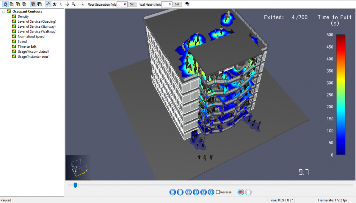
- Once the Generating Occupant Contour dialog box has completed, click
 Play to view the results with the contour overlay.
 - On the Navigation panel, right-click the Time to Exit contour plot and click Properties.
- On the Time to Exit Properties dialog box, in the Opacity Source dropdown, select feather below.
- In the Feather Threshold box below the Opacity Source dropdown, type
1and click OK.
You have successfully modified and viewed a contour plot. Save the plot modifications to MyFundamentals.pfrv.
Create a Camera Tour
In this section, you will create a Camera Tour like the one in Example Camera Tour to highlight key areas in the simulation.
To create a Camera Tour
- Stop the simulation in the playback menu
- In the 3D Results window, on the Navigation panel right-click
 Views and click New Tour.
 - Create the first keyframe.
- On the View toolbar, click
 Reset All to show the rooftop view.
 - On the property panel, click Add. This inserts a keyframe at the current time and the current camera position.
- Leave the Time (s) set to
0and the Transition to Stationary as seen in Table 1. This means we will hold the first view.
- On the View toolbar, click
- Create the second keyframe.
- Move the time slider to about 10 seconds.
- Scroll the mouse wheel to zoom in and get a closer view. Move the viewpoint so that you are looking at the elevator doors.
- On the property panel, click Add.
- Set the Time (s) to
10and the Transition to Move to Next. This means at 10 seconds we will begin to move to the next keyframe.
- Create the third keyframe.
- On the 3D view, right-click and drag to rotate down to the front face of the building with the stairs. Pan and zoom as necessary to capture the whole building inside the 3D view.
- Move the time slider to about 30 seconds.
- On the property panel, click Add.
- Set the Time (s) to
30and the Transition to Stationary. This means we will hold this view.
- Create the fourth keyframe.
- Move the time slider to about 40 seconds.
- On the property panel, click Add.
- Set the Time (s) to
40. The Transition selection does not matter. - Click Close to complete the tour.
| Time (s) | Transition | |
|---|---|---|
| 1 | 0.00 | Stationary |
| 2 | 10.0 | Move to next |
| 3 | 30.0 | Stationary |
| 4 | 40.0 | Stationary |
To run the tour
- Double-click Tour
- Move the time slider to 0 seconds
- Click Play. The tour should look like Example Camera Tour.
To save the tour to a new visualization file
- In the File menu, click Save Results Visualization As
- Save as MyFundamentals-tour.pfrv.
You have successfully created, viewed and saved a camera tour to a results visualization file.
Export a Movie With a Density Contour Tour
In this section, you will create a video file using the tour.
To export a video
- In the Navigation panel, double-click the
 Tour camera tour, if it is not already active.
 - On the Navigation panel, double-click the Density contour plot.
Results will run a contouring script.
- Move the time slider to 0 seconds.
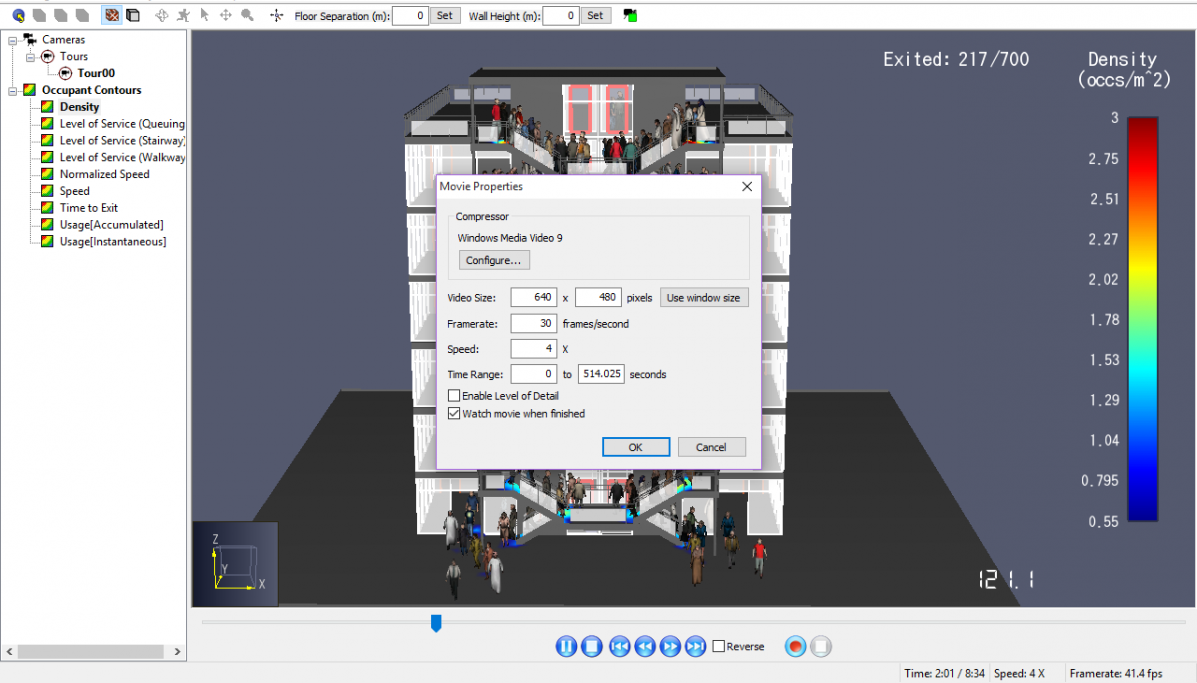
- On the File menu, click Create Movie.
- Save the file as
Fundamentals.mp4. Pathfinder also supports the*.wmvWindows Media Format. - On the Movie Properties dialog box click OK.
- Select the desired settings.
- Click OK.
- Once the Movie Progress dialog box completes, the file should play in your default video player application.
You have successfully created a results movie. The movie should look like Example movie with a Density Contour Tour..
Conclusion
Thank you for completing the Pathfinder Fundamentals tutorial. You should now have an understanding of the fundamentals. There are many advanced topics to cover. Refer to Pathfinder Tutorials for additional learning material.
To download the most recent version of Pathfinder, please visit the Pathfinder Download page. Please contact support@thunderheadeng.com with any questions or feedback regarding our products or documentation.
Related Tutorials
In this tutorial we show how to fix three problems that can occur when BIM (Building Information Modeling) or CAD (Computer-Aided Design) models into Pathfinder.
(Legacy) Tutorial to experience the fundamental features of PyroSim
Video tutorial demonstrating how to fix geometry problems related to DWG importation.
Tutorial demonstrating how to import IFC files to Pathfinder.
Tutorial Demonstrating how to model pressure leakage using Pyrosim
Tutorial demonstrating how to model ramps three different ways and how to import sketchup geometry in PyroSim.
Tutorial demonstrating how to make ramps in Pathfinder.
Tutorial demonstrating how to model passenger movement in a large subway station.