Introduction
This example demonstrates how to import a file as a background image and then create the model by sketching.
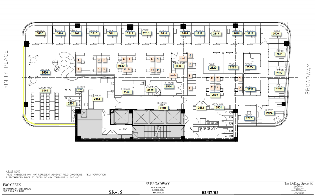
The image used is the office space of Fog Creek (we use their FogBugz software to track our bug reports) and is displayed at their website.
Right click Figure 1 and Save link as with the file name of 15floorplan.png.
The following video demonstrates how to import a blueprint in jpg format and then create the Pathfinder evacuation model by sketching on top of the blueprint.
The rest of this tutorial provides a walkthrough of this feature.
Import Background Image
To select English measurements:
- On the View menu, click Units and select EN.
We will begin by importing the background image for sketching:
- On the View menu, uncheck Show Snap Grid. This will allow us to sketch in the 2D view without snapping to the grid.
- On the Model menu, click Add a Background Image.
Open the
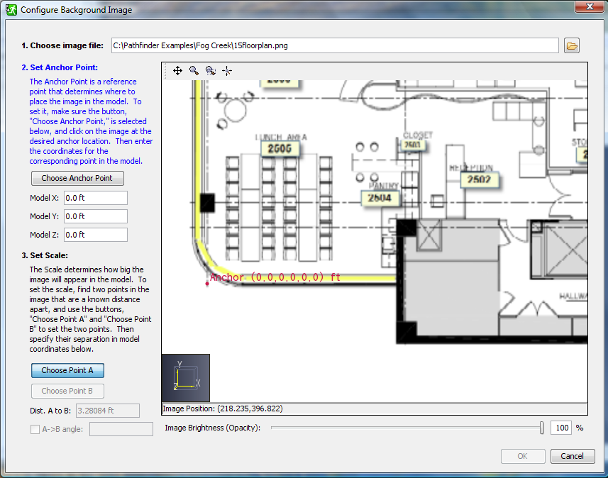
15floorplan.pngfile. This will display the Configure Background Image dialog. - We first define the "Anchor Point" for the image.
Type the coordinates as Model X:
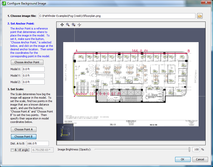
0.0 ft, Model Y:0.0 ft, and Model Z:0.0 ft. Click the Choose Anchor Point button and click on the mark in the lower left of the image. - We next define two points that will be used to scale the image geometry and to rotate the image (if needed).
Click the Choose Point A button and click on the cross mark in the upper left of the image.
Click the Choose Point B button and click on the cross mark in the upper right of the image.
In the Dist. A to B textbox, type
166.0 ft.
Sketch the Rooms
We will now sketch the rooms on top of the background image. Remember that holding the ALT key down temporarily disables snap-to. Also, after you define any room, you can select the room and then select any of the points that define the shape and drag the point to adjust the shape.
To sketch the rooms:
- In the View toolbar, click Top View
 .
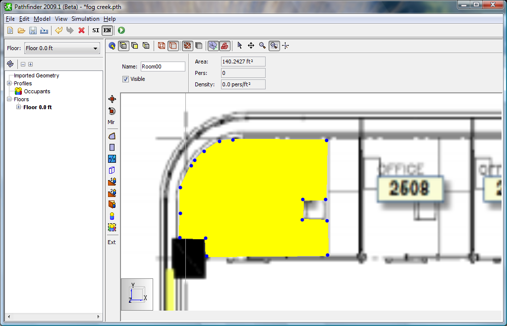
. - Zoom in on the top left of the background image and, in the left toolbar, click Add a Polygonal Room
 .
Click to define the periphery of the room.
Use a right-click to draw the last line that closes the polygon, as shown in Figure 4.
How precise you want to be when defining the room boundaries depends on your goals.
In general, the results of the evacuation analysis are relatively insensitive to exact precision of the room dimensions.
.
Click to define the periphery of the room.
Use a right-click to draw the last line that closes the polygon, as shown in Figure 4.
How precise you want to be when defining the room boundaries depends on your goals.
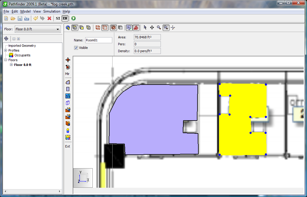
In general, the results of the evacuation analysis are relatively insensitive to exact precision of the room dimensions. - With the created room selected, type
75%in the Opacity box. This will make the room 75% solid (25% transparent) so that the underlying background image can still be seen. - Repeat for the adjacent office, as shown in Figure 5.
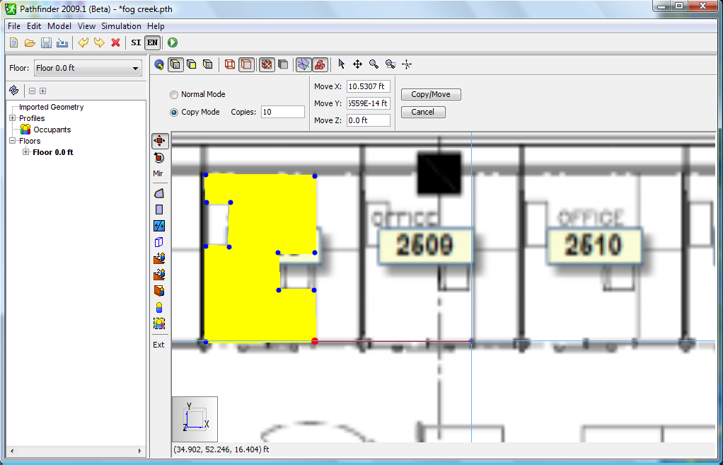
- We will now make copies of the second office.
Select the second office, then, in the tools toolbar, click Copy/Move Objects
 .
Select Copy Mode.
In the Copies box, type
.
Select Copy Mode.
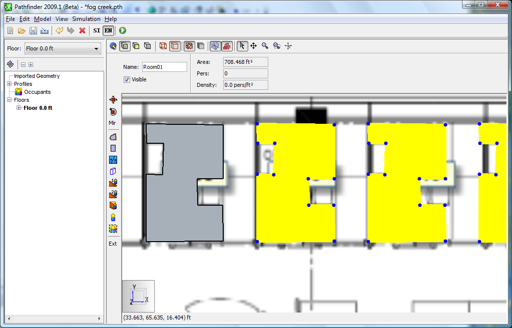
In the Copies box, type 10. To define how far to move each copy, click on the lower right corner of the polygon that describes the office and then click on the corresponding point in the adjacent office, shown in Figure 6. The second click will make the copies, as shown in Figure 7. - You will probably need to zoom in and adjust the exact positions of the offices. Select Normal Mode to move an office without making a copy. When completed, your model should resemble Figure 8.
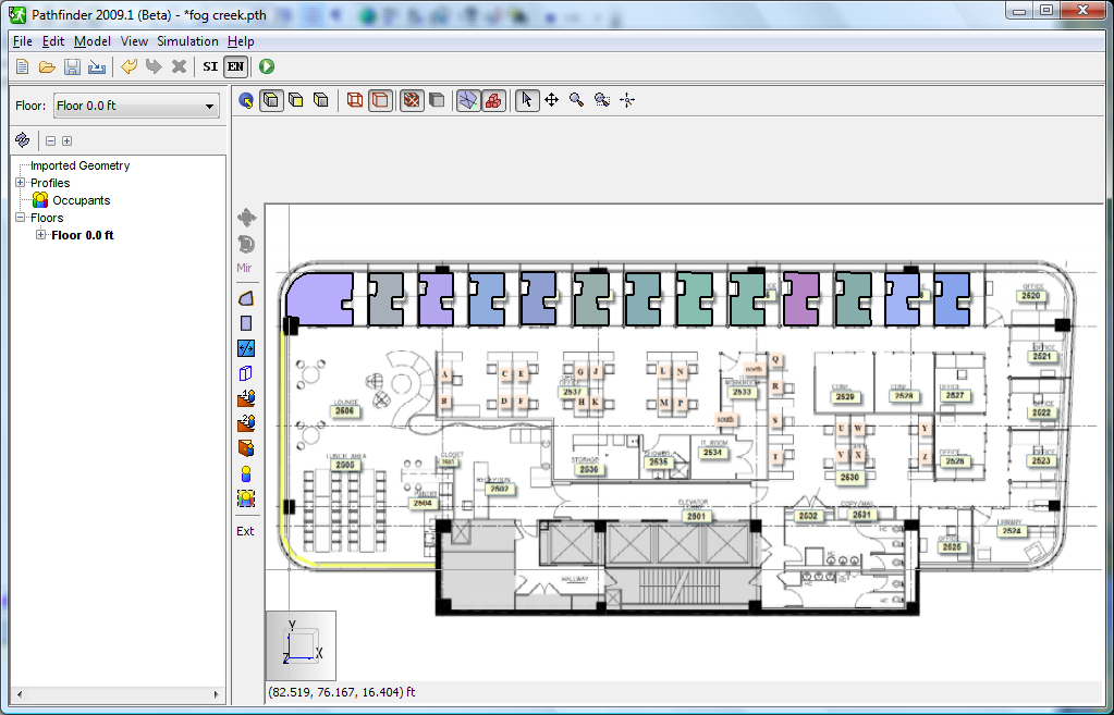
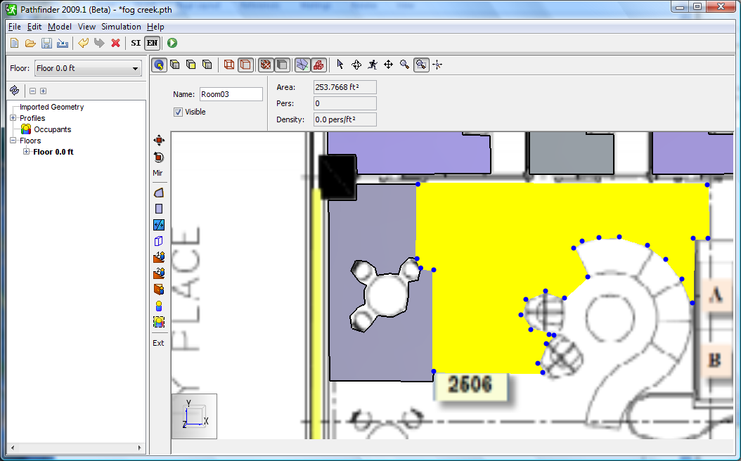
- Continue to sketch the rooms. Figure 9 shows sketches made that go around furniture. As a second sketch is made next to an existing room, the cursor will snap to the existing room coordinates. Hold the CTRL key and select both rooms, then right-click and select Merge. Continue this process to complete the sketch.
- You can cut holes in an existing room by drawing a new polygonal room on the existing room and deleting the polygon.
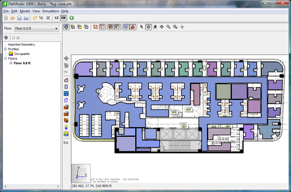
- Continue the sketching process until you have made all the rooms for the office. Note that we can leave the walls with a finite thickness separating the rooms. After some time, your model should resemble Figure 10.
Add Doors
Doors are added to connect all offices to the open walking space.
- In the View toolbar, click Top View .
- Double-click Add a new Door
 .
By default the doors are 32 inches wide.
The Max Depth is the maximum thickness the tool will use to search for adjoining space.
Depending on how accurately your model is sketched, you might need to increase the value.
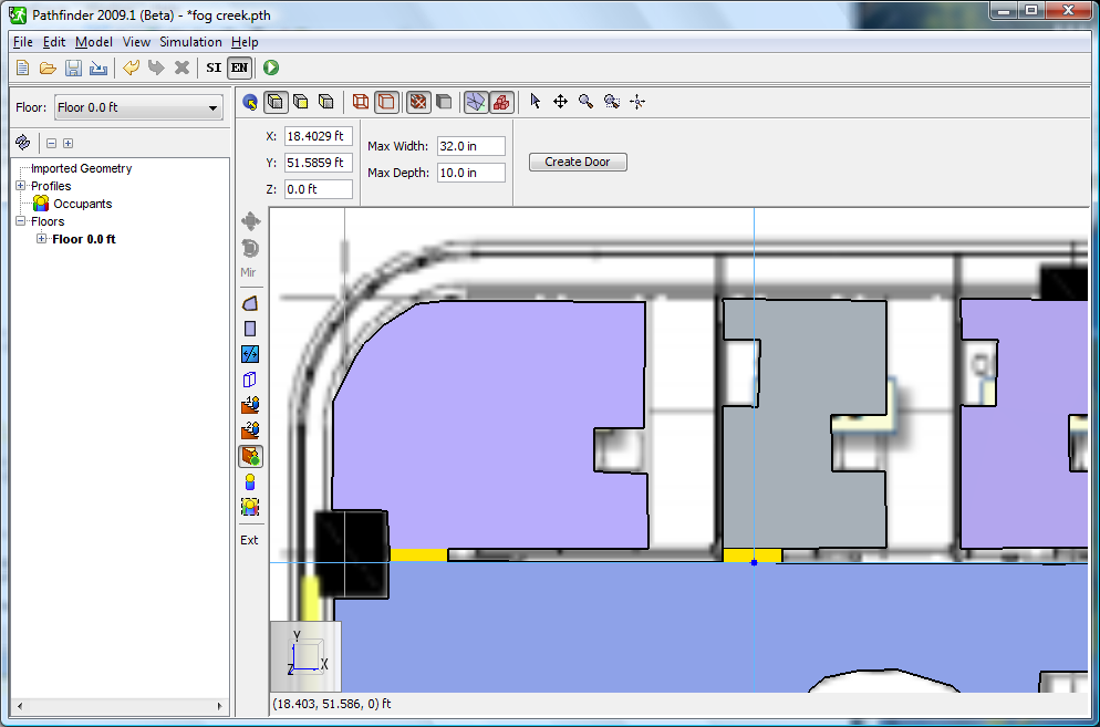
.
By default the doors are 32 inches wide.
The Max Depth is the maximum thickness the tool will use to search for adjoining space.
Depending on how accurately your model is sketched, you might need to increase the value. - Zoom in to the upper left of the model and move the mouse to the location for the door and the tool will snap to the adjoining spaces as shown in Figure 11.
- Continue adding doors until your model resembles Figure 12.
Add Occupants
We will add 80 occupants, 50 placed in offices and open space and 20 and 10 placed in the two conference rooms.
- Double-click Add an Occupant
 .
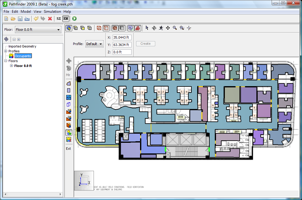
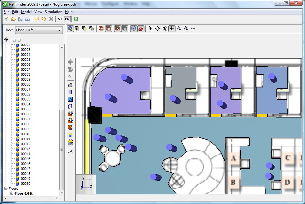
Click to position 50 occupants in offices or open space, as shown in Figure 13.
.
Click to position 50 occupants in offices or open space, as shown in Figure 13. - To add occupants to the conference room, right-click on the left conference room and in the context menu, click Add Occupants.
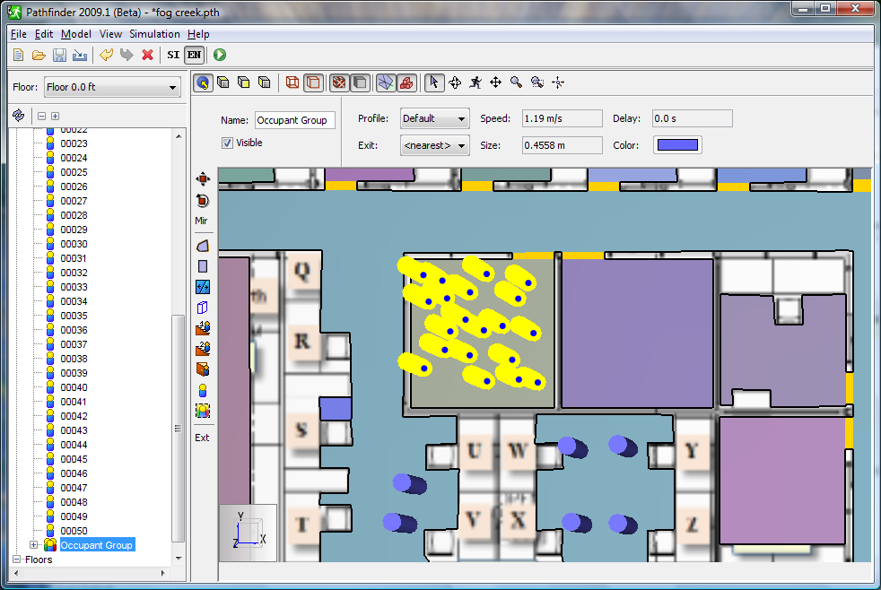
- For Placement, select Random.
In the By Number box, type
20. Click OK to close the dialog and add the occupants, as shown in Figure 14. - Repeat to add 10 occupants to the adjacent conference room.
Run Simulation
To run the simulation:
- On the File menu, select Save.
- Save the model to a new folder on your computer and name the file
fog_creek.pth. - On the toolbar, click Run Simulation
 .
.
View Results
When the simulation is finished, the 3D Pathfinder results window will display.
To view results:
- Click the Play button.
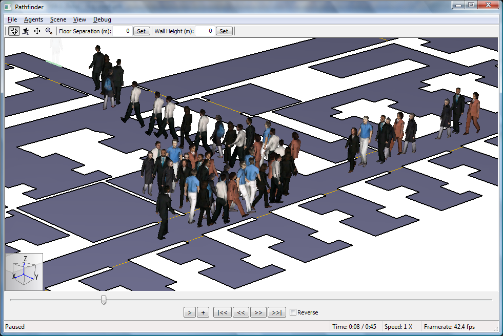
- At any time click the Pause or Stop button. You can drag the time line to control the animation.
- To view occupants as people, click the Stop button, on the Agents menu, click Show as People, then click the Play button. Your simulation should resemble Figure 15.
To download the most recent version of Pathfinder, please visit the Pathfinder Support page and click the link for the current release. If you have any questions, please contact support@thunderheadeng.com
Related Tutorials
Video tutorial demonstrating how to fix geometry problems related to DWG importation.
In this tutorial we show how to fix three problems that can occur when BIM (Building Information Modeling) or CAD (Computer-Aided Design) models into Pathfinder.
Tutorial to experience the fundamental features of Pathfinder
Tutorial demonstrating how to model ramps three different ways and how to import sketchup geometry in PyroSim.
Tutorial demonstrating how to make ramps in Pathfinder.
(Legacy) Tutorial to experience the fundamental features of PyroSim
Video tutorial demonstrating how to avoid creating unwanted gaps in the geometry of a Pathfinder model.
Tutorial demonstrating how to import IFC files to Pathfinder.