 |  |
General usage information for PyroSim
There is a newer version of this document. To view the latest version, click here.
Thunderhead Engineering makes no warranty, expressed or implied, to users of PyroSim, and accepts no responsibility for its use. Users of PyroSim assume sole responsibility under Federal law for determining the appropriateness of its use in any particular application, for any conclusions drawn from the results of its use, and for any actions taken or not taken as a result of analyses performed using these tools.
Users are warned that PyroSim is intended for use only by those competent in the fields of fluid dynamics, thermodynamics, combustion, and heat transfer, and is intended only to supplement the informed judgment of the qualified user.
The software package is a computer model that may or may not have predictive capability when applied to a specific set of factual circumstances. Lack of accurate predictions by the model could lead to erroneous conclusions with regard to fire safety. All results should be evaluated by an informed user.
All other product or company names that are mentioned in this publication are tradenames, trademarks, or registered trademarks of their respective owners.
Throughout this document, the mention of computer hardware or commercial software does not constitute endorsement by Thunderhead Engineering, nor does it indicate that the products are necessarily those best suited for the intended purpose.
We thank Kevin McGrattan, Simo Hostikka, Randall McDermott, Jason Floyd, Craig Weinschenk, Kristopher Overholt, and Glenn Forney in the Building and Fire Research Laboratory at the National Institute of Standards and Technology and the VTT Technical Research Centre of Finland. They are the primary authors of the Fire Dynamics Simulator and Smokeview, without which PyroSim would not exist. They have been gracious in their responses to our many questions.
We would like to gratefully acknowledge the RJA Group for their collaboration with Thunderhead engineering in the development of PyroSim. Feedback and testing from the engineers at RJA has improved the usability and quality of PyroSim.
Development of PyroSim was originally supported by the National Science Foundation under Grants DMI-0232401 and DMI-0349759. Any opinions, findings, and conclusions or recommendations expressed in this material are those of the authors and do not necessarily reflect the views of the National Science Foundation.
PyroSim is a graphical user interface for the Fire Dynamics Simulator (FDS) version 6.7.5. FDS is closely integrated into PyroSim. FDS models can predict smoke, temperature, carbon monoxide, and other substances during fires. The results of these simulations are used to ensure the safety of buildings before construction, evaluate safety options of existing buildings, reconstruct fires for post-accident investigation, and assist in firefighter training.
FDS is a powerful fire simulator which was developed at the National Institute of Standards and Technology (NIST). FDS simulates fire scenarios using computational fluid dynamics (CFD) optimized for low-speed, thermally-driven flow. This approach is very flexible and can be applied to fires ranging from stove-tops to oil storage tanks. It can also model situations that do not include a fire, such as ventilation in buildings.
The PyroSim interface provides immediate input feedback and ensures the correct format for the FDS input file.
Some highlights include:
In summary, PyroSim helps you quickly and reliably build complex fire models.
You can download the current version, sign up for a free trial, and purchase the software from the PyroSim Support Page. This page also provides instructions for installation and activation. Troubleshooting info can be found on the PyroSim FAQs page. There is no functional difference between the trial version of PyroSim and the full version, the only limitation is the trial license duration.
When installing PyroSim, the installer will either upgrade an existing version or install PyroSim to a new location, this behavior is based on the version. In the case of minor updates (e.g. upgrading from PyroSim 2020.1 to PyroSim 2020.2), the installer will remove the older version and replace it with the new version. When installing a major update (e.g. PyroSim 2019 to PyroSim 2020), the older version will not be modified and the newer version will be installed to a different folder.
Administrator privileges are required to install PyroSim. This is necessary because the installer adds processes to the operating system for license management and parallel FDS simulation.
PyroSim will regularly check for and notify the user of available updates to the software when configured to do so. By default, PyroSim will check for updates on startup and display the relevant information in the Check For Updates dialog when one is available.
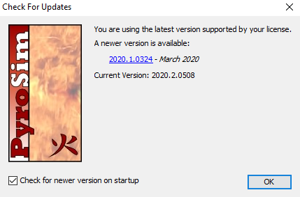
Users can also access this dialog by navigating to Help→Check For Updates
The dialog can be disabled on startup by unchecking Check for newer version on startup.
In this section we make some suggestions that can help speed your model development. The big issues most users will face are: selecting a mesh, defining your geometry, selecting a reaction, and defining the correct boundary conditions.
We will broadly discuss each of those topics, but before you start thinking about them please:
The analyst will always need to balance solution time and accuracy. Reducing the mesh size by a factor of 2, will result in approximately a factor of 16 more computation time (a factor of 8 due to the number of cells and an additional factor of 2 due to reduced step size).
Two criteria will control the applicable mesh size:
For fire plumes, an initial mesh size estimate can be obtained as a fraction of the characteristic fire diameter (D*), see Materials of the Fire Dynamics Simulator Technical Reference Guide Volume 3: Validation. You can download a D* calculator from the PyroSim Resources page. Initial calculations should be done with a coarse mesh (\(\frac{D^{*}}{5}\)), but a mesh size study must be employed to analyze the suitability of the mesh (\(\frac{D^{*}}{20}\)).
An example of a convergence study for jet fans (no fire) can be found in the series of posts Modeling Jet Fans found on the PyroSim Tutorials web page. Here the solution was compared with experimental data.
In some problems the mesh resolution must be selected to adequately represent the geometry. An example where geometry controlled the mesh size is the modeling of a wood crib where each stick had a small diameter (see Modeling Fire, Part 4 - Combustion with HRR, Ignition, and Burn Away on the Thunderhead website).
By default, no reaction is specified, a reaction is only needed if there will be a fire in the simulation. In FDS, a reaction defines not only the fuel and the products but also the Heat of Combustion. Once the heat of combustion and the desired HRR is known, FDS calculates the fuel mass flow rate from the surface.
For most situations, it is sufficient to use the "Simple Chemistry" model, where a single fuel species is composed of \(C\), \(H\), \(O\), and \(N\) that reacts with oxygen (\(Air\)) to form the product species consisting of \(H_{2}O\), \(CO_{2}\), \(Soot\), \(N_{2}\), and \(CO\). The user specifies the chemical formula of the fuel along with the yields of \(CO\) and \(Soot\), and the volume fraction of hydrogen in the \(Soot\), \(X_{H}\). A limited number of reactions are included in FDS and can be added from the library.
See Chapter 12 of the FDS User Guide for a more detailed discussion of combustion. The PyroSim Resources page provides Combustion and Fuel Composition calculators.
Parallel processing can speed the solution. In general, our experience indicates that running on multiple cores on the same computer offers the most significant improvement. Using multiple computers in a cluster can make it possible to solve larger problems, but the communication delays between computers tend to cancel the speed improvement of parallel processing.
The good news is that that standard installation of PyroSim includes support for parallel processing on the same computer. All the user must do is define multiple meshes and then select Run FDS Parallel.
PyroSim includes tools to manage multiple meshes. One effective strategy is to first define a single mesh that spans the entire model. Then use the PyroSim mesh splitting tool to create multiple meshes. You can then change the resolution of selected meshes using the Refine Mesh option and all the meshes will automatically stay correctly aligned.
All geometry in FDS is defined at the mesh resolution. Even if you input the geometry of an obstruction or vent to lie between cell corner points, when FDS runs the solution, all the geometry will be "snapped" to the grid.
If you are drawing your own geometry in PyroSim, you can select the Snap to Model Grids option that will ensure that your geometry matches the grid. You can also ensure that objects will fill entire grid cells rather than a cell face by turning on the Thicken option in the obstruction properties, see Creating Obstructions.
In our experience, numerical instabilities that may occur during the solution are the result of an error in the model, not an error in FDS. The numerical instability typically arises due to either a pressure increase (or decrease) in a mesh. If you see this error, add a pressure sensor to your model and see what is happening to the pressures. Problems typically occur because of how boundary conditions have been defined.
Some common problems with boundary conditions include:
Each PyroSim release comes bundled with FDS. A particular PyroSim release is designed and tested against the bundled version of FDS. You can use PyroSim to run any version of FDS, however PyroSim will generate the input file based on the bundled version of FDS and it is important to understand differences in input format between the FDS versions before changing PyroSim’s FDS version.
To change the version of FDS used by PyroSim:
In preparing this manual, we have liberally used descriptions from the FDS User’s Guide (McGrattan, et al., 2015). Links to the FDS Users Guide, the FDS Technical Reference, and the Smokeview Users Guide are included in PyroSim on the Help menu. You can also download documentation, executables, and verification and validation examples at: https://pages.nist.gov/fds-smv/ .
Thunderhead Engineering
403 Poyntz Avenue, Suite B
Manhattan, KS 66502-6081
USA
Sales Information: sales@thunderheadeng.com
Product Support: support@thunderheadeng.com
Phone: +1.785.770.8511
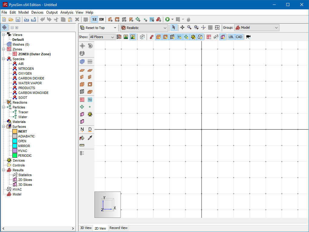
PyroSim provides four editors for your fire model: the 3D View, 2D View, Navigation View, and the Record View. These all represent your current model. If an object is added, removed, or selected in one view, the other views will simultaneously reflect the change.
Each view is briefly described below.
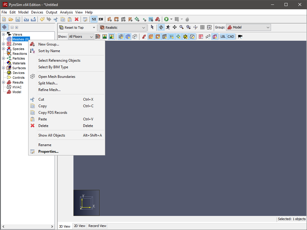
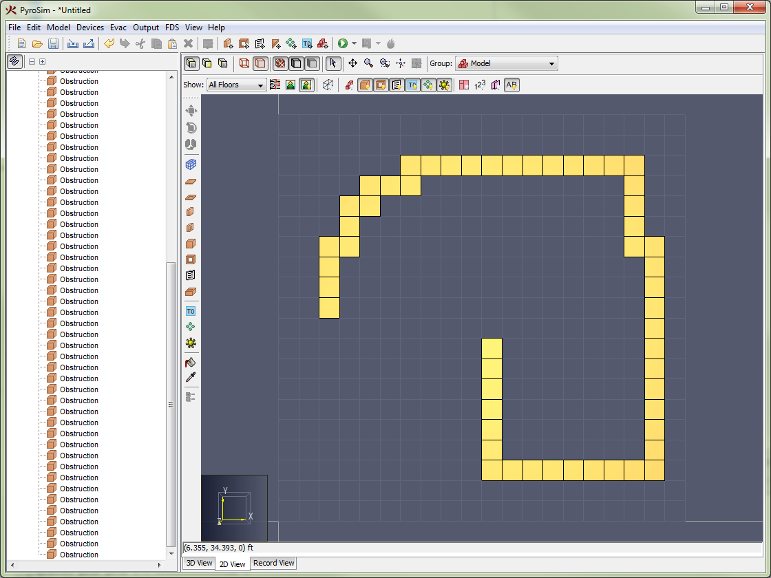
The navigation view is a tree-like view on the left side of the PyroSim main window. An example of this view in use is shown in Figure 2. When you right-click on an item in this view, a list of the functions PyroSim can perform on that item is shown. To rearrange objects in the Navigation view, make a selection and then drag the object(s) to the new location.
Use the 3D view to rapidly obtain a visual image of the model and perform some drafting. In this view, the user can navigate through the model in 3D and select objects. This view also provides display filters to quickly show/hide entire categories of objects or switch between floors. In addition, any drafting that requires objects to be snapped to faces of other objects, such as drawing a vent on an obstruction or attaching a measuring device to a solid can be easily achieved in this view. For more information on drafting, see Drawing in PyroSim.
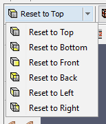
The traditional orthographic views are pre-programmed into PyroSim and are valid in both the 3D and 2D views. It is also possible to save custom camera views, for more information, see Views.
To change the camera view, select the desired view in the drop-down menu, as shown in Figure 3 or press the appropriate hotkey from Table 1.
| View | Hotkey |
|---|---|
| Front | CTRL+1 |
| Back | CTRL+2 |
| Left | CTRL+3 |
| Right | CTRL+4 |
| Top | CTRL+5 |
| Bottom | CTRL+6 |
The drop-down menu is also a clickable button that will reset to the most recent view.
There are several tools that can be used to navigate the model and select objects. The tools for the 3D view are found in the navigation toolbar above the 3D view as shown in Figure 4.

| |
The model can also be zoomed in and out with any of the navigation tools by using the scroll wheel. Scrolling up zooms in and scrolling down zooms out. With all but the Roam Tool, using the scroll wheel will zoom in on the point under the cursor. With the Roam Tool, the scroll wheel only zooms the center of the view.
At any time, the camera’s view can be reset to see the entire extents of the model by clicking the Reset View button (![]() ) or pressing CTRL+r.
In addition, the camera can be reset to only the currently selected objects by clicking the Reset to Visible button (
) or pressing CTRL+r.
In addition, the camera can be reset to only the currently selected objects by clicking the Reset to Visible button (![]() ) or pressing CTRL+e.
Resetting the view also has the effect of changing the orbit center when orbiting.
) or pressing CTRL+e.
Resetting the view also has the effect of changing the orbit center when orbiting.
Orbiting is the action of spinning the camera about its focal point, which is the center of the model or center of the selection, depending on which reset action was last performed. By default, orbit works as if there is an invisible sphere around the model on which you click and drag the mouse to spin. Alternatively, orbiting can be performed similarly to Smokeview by going to the View menu and selecting, Use Smokeview-like Navigation. In this mode the camera spins about the Z axis with left and right mouse movements and about the local X axis with up and down movements.
There are several ways to filter the objects shown in the 3D view. Filtering can be performed with clipping planes that are associated with floors or through filter buttons that can quickly show/hide categories of objects.
To use clipping, the user must first define floors for the model as discussed in Floors. Once the floors are defined, a floor can be selected by using the Floor Drop-down above the 3D or 2D view as shown in Figure 7.
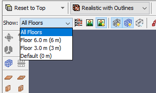
Once a floor has been selected, its clipping planes will be applied to the entire scene to only show objects within the clipping region.
Filtering can also be performed using the filter toolbar buttons as shown in Figure 8. Selecting/deselecting these buttons will quickly show/hide all objects of a specific type, such as obstructions, holes, vents, etc.

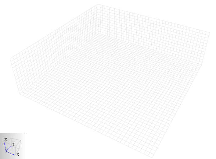
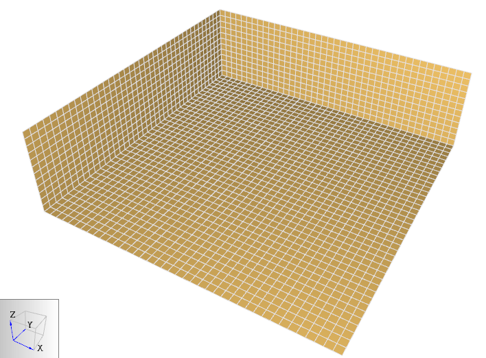
Filtering can also be applied to meshes but in a slightly different way. Instead of showing/hiding all meshes, the user can selectively show/hide three different elements of them using the mesh filter toolbar shown in Figure 9. This toolbar selectively allows viewing mesh grid lines, mesh boundaries, and mesh outlines. Filtering mesh elements shows the different mesh elements. Figure 10 shows the grid lines, Figure 11 shows the boundary, and Figure 12 shows the outline.

 |  | 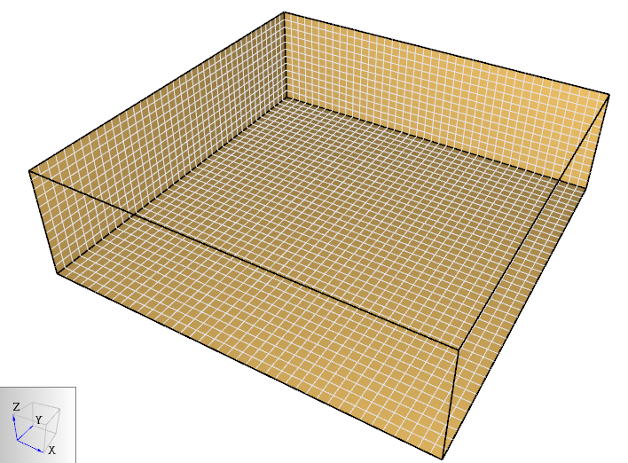 |
Background images attached to floors can be quickly shown/hidden using the Show Background Image filter button (![]() ) next to the floor drop-down.
) next to the floor drop-down.
The 2D view is mostly the same as the 3D view with some key differences:
The Record View shows an up-to-date display of the FDS input file currently represented by the PyroSim model. This view is divided into two sections, the Model Records and the Additional Records.
This read only sections allows the user to see an exact copy of the file that will be input into the FDS simulator based on their current model.
The user adjust font size of this using the Increase Font Size (![]() ) and Decrease Font Size (
) and Decrease Font Size (![]() ) buttons at the top of the page.
Other settings related to the file display can be toggled through the Preferences menu item.
) buttons at the top of the page.
Other settings related to the file display can be toggled through the Preferences menu item.
Due to the complexity of the FDS simulator, it is difficult to support all possible records and input files. The Additional Records section of the Record View can be used to inject lines of text into the top of the FDS input file.
Scenarios can be used to manage variations of a single model. Any time a simulation object is enabled or disabled, that change is retained by only the current scenario.
Multiple fire scenarios can be managed using the Scenarios box on the main toolbar. The Edit Scenarios dialog, activated by the toolbar button next to the Scenarios box, can be used to manage scenarios and examine which objects are enabled in a specific scenario.
For models that use multiple scenarios, a bulk export option is available on the File menu in the Export submenu, called Export Scenarios. Using this feature will export an FDS input file (and other supporting files) for each scenario in subfolders where the PSM file has been saved. A BAT file will also be produced that can be double-clicked in Windows Explorer to run all scenarios in sequence.
You can learn more about the scenarios feature by following along with the PyroSim Scenarios Tutorial.
Images of the current display can be saved to a file by opening the File menu and clicking Snapshot. The user can specify the file name, image type (png, jpg, tif, bmp), and the resolution. A good choice for image type is Portable Network Graphics (png).
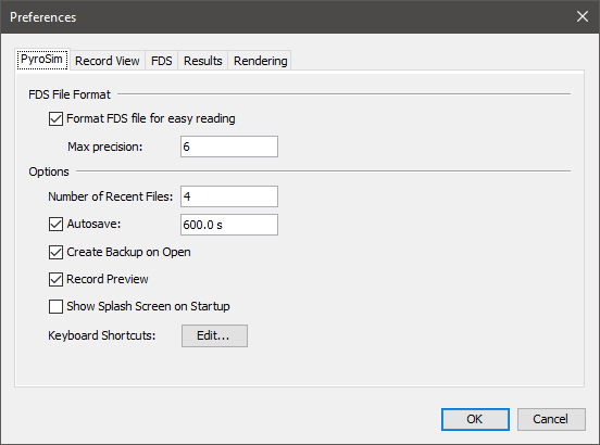
PyroSim preferences can be set by going to the File menu and choosing Preferences. Any changes to the preferences will be set for the current PyroSim session and be remembered the next time PyroSim is started. The preferences are split into several groups, including PyroSim, Record View, FDS, Results, and Display preferences.
These describe global PyroSim preferences as shown in Figure 13.
testing.psm for example) becomes corrupted, then you can find the file that starts with a tilde like ~testing.psm shown in Figure 14.
This file is sometimes preferred if you have a crash, as it will be the most up to date version of your work before your crash.
If it cannot be opened or results in an immediate crash, there is another backup file described next that is the second best option.
The default setting enables this feature and saves every 10 minutes.
In some cases, when working with large models, this can cause unexpected delays during the save and some users prefer to disable the feature and save manually.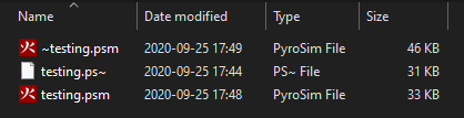
testing.~sm shown in Figure 14.
Rename (recommended) or delete your current working file, then change the file extension on this backup file, changing the tilde in the extension (.~sm) to a p character to get .psm.
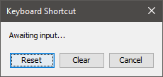
You can now open the new .psm file as you normally would.The Keyboard Shortcuts dialog is launched from the PyroSim preferences panel. These preferences bind combinations of modifier keys (ALT, CTRL, SHIFT, etc.) with other key presses to activate PyroSim actions.
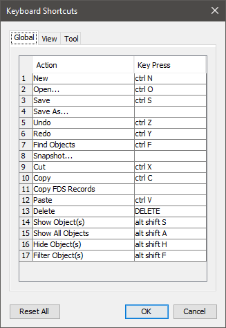
The dialog is divided into three sections.
To change the keybinding for an action, click the value in the Key Press column. This launches an editor window (Figure 16) with four options.
Some keyboard shortcuts are used by Java UI components. If a shortcut does not result in the expected behavior, it may be in direct conflict with a preexisting Java shortcut. It is best practice to avoid these conflicts (Default Swing key bindings).
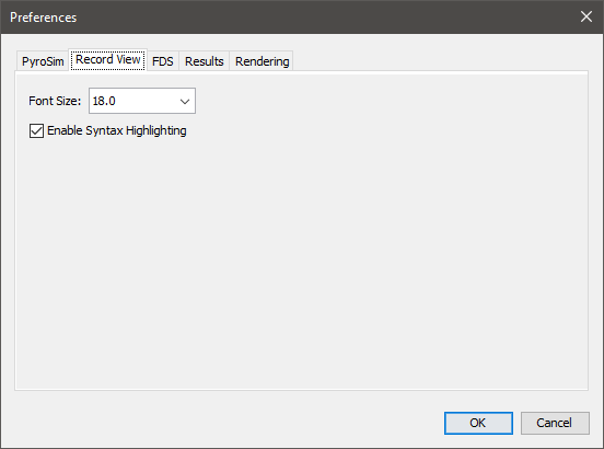
These preferences control the visualization of the FDS input file in the Record View. They can be seen in Figure 17.
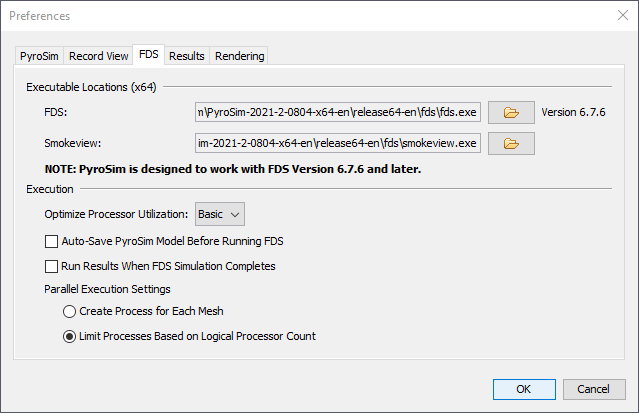
These preferences define the execution of FDS within PyroSim. They can be seen in Figure 18.
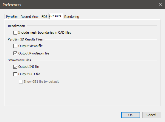
There are a number of preferences that control the files created by PyroSim when an FDS simulation is started that affect the results (either PyroSim 3D Results or Smokeview).
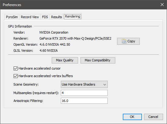
These preferences define advanced 2D and 3D display properties, as shown in Figure 20. They can be used to improve display performance on complex models, but they tend to create problems for some older graphics cards, including crashing. For this reason, they are turned off when running in safe mode.
PyroSim stores data related to user preferences in a file called PyroSim.props. By default, this file can be found in one of the following locations.
%APPDATA%\PyroSim\PyroSim.props%PROGRAMDATA%\PyroSim\PyroSim.props
If at least one of these files exists, PyroSim will use it to load the user preferences.
If both files exist, PyroSim will load user preferences from both files, giving preference to the file located in the APPDATA folder.
This way the preference file located in the PROGRAMDATA folder can be shared among multiple machines, and the file located in the APPDATA folder on each machine overrides the shared settings.
The PROPS file is stored in a plaintext format, and can be viewed or edited with any conventional text editor.
While it is not recommended to edit the file directly, some troubleshooting techniques may involve deleting the PROPS file so that a new one can be created from scratch by PyroSim.
Configurations for hotkeys in PyroSim is stored in a separate file named keybindings.json located in the APPDATA folder.
Models can be created in either English or Metric units. To select a system of units, on the View menu, click Units, then click the desired unit. PyroSim will automatically convert your previous input values into the unit system you select. The Record View will always display values in the appropriate FDS units, regardless of what unit system you choose to work in.
To select a Default, Black Background, White Background, or Custom color scheme, on the View menu, click Color Scheme.
The custom color scheme is defined in the PyroSim.props file in the PyroSim installation directory (For Windows 10 look in %USERPROFILE%\AppData\Roaming\PyroSim\PyroSim.props while some older operating systems use C:\Program Files\PyroSim).
PyroSim.props fileColors.Custom.axis=0xffff00 Colors.Custom.axis.box=0x404040 Colors.Custom.axis.text=0xffffff Colors.Custom.background=0x0 Colors.Custom.boundary.line=0xffffff Colors.Custom.grid=0x4d4d66 Colors.Custom.group.highlight=0xffff00 Colors.Custom.heatDetector=0xff0000 Colors.Custom.obst=0xff0000 Colors.Custom.obst.highlight=0xb2b200 Colors.Custom.origin2D=0x737373 Colors.Custom.smokeDetector=0xff00 Colors.Custom.snap.point=0xff00 Colors.Custom.snapto.grid=0x404040 Colors.Custom.snapto.points=0xc0c0c0 Colors.Custom.sprk=0xff Colors.Custom.text=0xffffff Colors.Custom.thcp=0xffff00 Colors.Custom.tool=0xff00 Colors.Custom.tool.guides=0x7c00
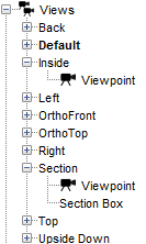
PyroSim.props filePyroSim provides the capability to save and recall view state from the 3D and 2D views in an object called a View. Views can also be used to specify clipping regions that limit the amount of the model shown in the 3D and 2D views. Views appear in the Navigation View as shown in Figure 21.
There can be multiple views in a model, but at any given time, there is always one active view. A new model will always start with one default view that has no view state associated with it. State can be added to the view as described in the sections, Viewpoints and Section Boxes.
Views are managed in the navigation view. From there, they can be created, deleted, grouped, rearranged, etc.
A view can be created in one of the following ways:
This will add a new view to the model, saving the current camera viewpoint and section box into the new view (see the following sections to learn more about viewpoints and section boxes). The new view will become the active view.
To delete a view, select it in the navigation view and in the Edit menu, select Delete. A view can only be deleted if it is not active.
To activate a view, perform one of the following:
Activating a view will restore all its saved state as described in the following sections.
View settings can be copied or moved between views. To copy settings such as the viewpoint or section box select Copy, located in either the navigation view or in the Edit menu. To paste the settings to another view, select the desired target view and in the Edit menu select Paste. To move settings from one view to another, in the navigation view, drag the setting to the desired view.
Each view can have one viewpoint associated with it. A viewpoint includes the 2D or 3D camera’s position, orientation, zoom, and camera type (3D versus 2D). When a viewpoint is saved, the current navigation tool is also saved with the view (Orbit, Roam, etc.). A viewpoint appears in the navigation view as a child item of a view and is labelled Viewpoint. This can be seen in Figure 21 for the two views, Inside and Section.
A viewpoint is automatically saved to newly created views. A viewpoint can also be explicitly saved in one of the following ways:
The scene camera can be reset to a viewpoint in one of the following ways:
A viewpoint can be removed from a view by selecting the item, Viewpoint, in the navigation view and deleting it.
When a view with a viewpoint is activated, the following occurs:
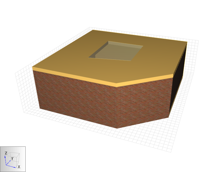
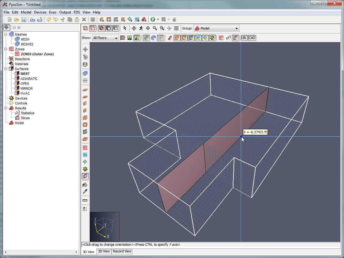
A section box may also be added to a view. A section box is a convex region defined by six sides that is used to limit the scope of visible geometry. All geometry outside the box is clipped from view. An example of the clipping is shown below.
 |  |
A section box can be created in several ways:
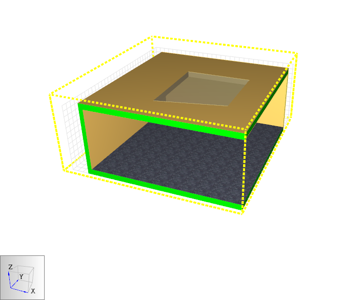
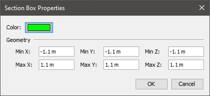
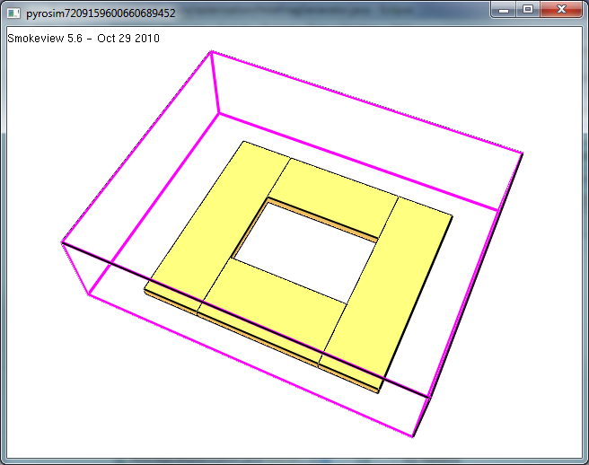
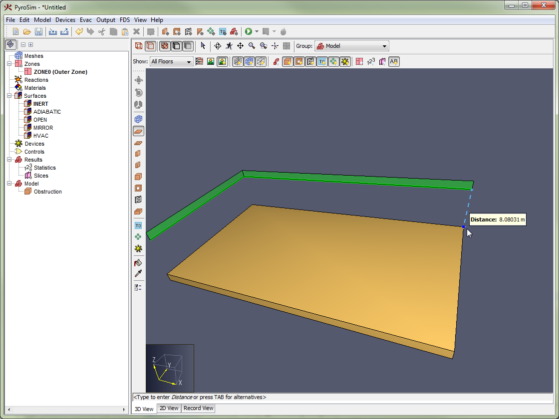
A section box is displayed as a dashed outline of the region. Each section box has a color associated with it that is used to display both the outline of the section box and the clipped portions of solid, clipped objects as shown in Effect of a Section Box, Figure 22. In this figure, the section box is green, so any geometry that is clipped including the walls and slab in the image are also colored green.
The scope of a section box can be edited by selecting the section box and manipulating it like any other geometric object, see Editing Objects. Section boxes can also be rotated and moved like other geometric items, see Transforming Objects.
The properties of a section box can be edited by either double-clicking the section box or by right-clicking it and selecting Properties.
See Figure 24 below.
The active section box can be disabled in the 2D or 3D view by de-selecting Enable Section Boxes in the View menu. The display for the section box can be independently hidden from view by de-selecting Show Section Boxes in the View menu.
A section box can also be reset to encompass the currently visible objects by performing one of the following:
Smokeview supports the concept of viewpoints, which are similar to PyroSim views. Smokeview viewpoints are defined by camera position, orientation, a navigation tool, and up to six axis-aligned clipping planes. Viewpoints are stored in the Smokeview INI file.
By default, when PyroSim prepares an FDS simulation or exports an FDS file, it also writes a Views file that can be read in the PyroSim 3D Results but not Smokeview. It does not write the views to the Smokeview INI file. This is to avoid view duplication in the 3D Results. This behavior can be changed, however, by turning off the Views file in the preferences, see Preferences. If turned off, PyroSim will instead write the view information to the INI file, which can be read in Smokeview.
At any time, the view information can be updated for the results without re-running the simulation by explicitly writing either the PyroSim Views file or the Smokeview INI file. This can be done by going to the File menu, and selecting either Export→PyroSim Viewpoints or Export→Smokeview INI, respectively.
While the Views file exports views exactly as defined in PyroSim, there are some limitations to how PyroSim views are exported to the Smokeview INI file:
In addition, if a view was saved in PyroSim with the Roam tool active, the Rotation type in Smokeview is set to Eye centered. For all other navigation tools, the Rotation type in Smokeview is set to 2 axis.
Smokeview viewpoints may also be imported into PyroSim. This is useful if additional views have been specified in Smokeview while viewing the results and those viewpoints should be preserved in PyroSim. To import Smokeview viewpoints, perform the following:
After importing, a new view group is added, containing one PyroSim view for each Smokeview viewpoint that was in the INI file.
Several files are used when performing a fire analysis using PyroSim. These include the PyroSim model file, the FDS input file, and FDS output files. This section describes how to load and save files in the formats supported by PyroSim.
When PyroSim is started, it begins with an empty model. You can close the current model and create a new empty model by opening the File menu and clicking New. PyroSim always has one (and only one) active model.
The PyroSim model file (PSM) is stored in a binary format that represents a PyroSim model. The PyroSim model contains all the information needed to write an FDS input file, as well as additional information such as obstruction grouping, floor heights, background images, and textures. This format is ideal for sharing your models with other PyroSim users.
To save a new model:
PyroSim model files have a PSM extension. To open a saved model:
A list of recently opened files is also available. To open recent files, on the File menu, click Recent PyroSim Files, then click the desired file.
PyroSim has an auto-save feature which stores a copy of your current model every 10 minutes. This file is automatically deleted if PyroSim exits normally, but if PyroSim crashes, you can recover your work by opening the autosave file. It can be found either in the same directory as your most recent PSM file, or in the PyroSim installation directory if your model was unsaved.
For more information about opening files saved with previous versions of PyroSim, please refer to Appendix A and Appendix B.
PyroSim supports write protection for a model. When write protection is enabled, users cannot modify a model (e.g. change geometry, edit surface properties, etc). This option can be enabled with or without password protection. If a model is write-protected, PyroSim will display notification in the application title bar.
To add write protection to a model:
The model will now be write-protected. Since a password was not used, a password will not be required to remove write protection.
To remove write protection from a model:
The model can now be edited. If needed, the dialog will require a password to release the lock.
PyroSim allows you to import existing FDS input files. When you import an FDS file, PyroSim will create a new PyroSim model from the imported file. During import, PyroSim will check for the validity of each record. If errors are detected, you will be notified. You may then make the required corrections and attempt to import the file again.
To import existing FDS models into PyroSim:
PyroSim supports file import for versions 4, 5, and 6 of FDS. For more information about opening files compatible with version 4 or 5 of FDS, please refer to Appendix A and Appendix B.
PyroSim also allows you to explicitly export the current model to an FDS input file. You can manually edit the file to take advantage of advanced FDS features, or to easily transfer the input file to a different machine or special version of FDS.
To export an FDS file:
The file exported by PyroSim will be compatible with version 6 of FDS.
PyroSim can import geometry from several CAD formats, including buildingSMART’s IFC format for Building Information Models (BIM), AutoCAD’s DXF (Drawing Exchange Format), DWG, FBX, DAE, OBJ, and STL files. Each type of file provides a variety of geometry that can either be directly represented as obstructions or as drawing guides in the PyroSim model.
Unlike FDS import, which completely replaces the current PyroSim model, CAD import appends the data to the current model. This facilitates the ability to import data from several CAD files into one PyroSim model. This is useful when there is one blueprint per floor of a building or a 3D building has been split into several sections, each in a separate file.
To import one of these files, under the File menu, select Import FDS/CAD File and select the desired file.
STL files will import as shown in Importing STL Files. For non-STL files, a step-by-step dialog will open as shown in Figure 25.
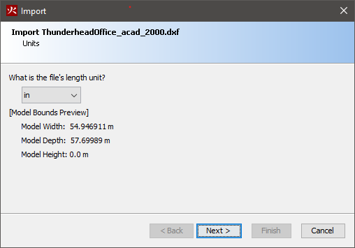
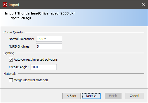
Choose Finish to import the file.
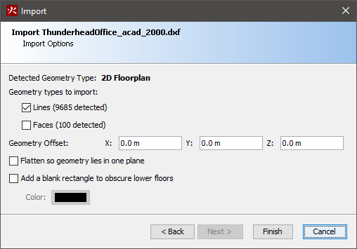
When PyroSim imports a CAD file, it will treat all 3D face data as obstructions and all other data (lines, curves, etc.) as separate CAD data. If an object in the file contains both face and CAD data, the entity will be split into two entities so that CAD data can be easily deleted or hidden after import using the CAD filter button on the 3D/2D View toolbar, see Filtering.
An object with CAD data can be snapped to while drawing in PyroSim but is not converted to any type of FDS geometry.
In DWG and DXF files, an entity with face data will either be treated as a single, solid obstruction with some volume or as a collection of thin obstructions depending on the entity type in the DWG/DXF file. These objects will be represented as FDS geometry. The following DWG/DXF entity types are treated as solids in PyroSim:
With the exception of IFC files, all other entities and objects from other CAD formats that contain faces are treated as collections of thin obstructions by PyroSim. They cannot be reliably treated as solid since there is no guarantee that their faces form a closed and non-self-intersecting shell or that this would even be desired.
Once the file is imported, PyroSim creates a hierarchy of groups and objects, such that there is one top group, named after the file. The next levels depend on the imported file type. For non-DWG/DXF files, the structure will mimic the node structure in the source file. For DWG/FXF files, the next level contains a group for every layer containing geometry. Under each layer group there are one or more objects representing the entities in the file. The following illustrates the hierarchy as it would appear in the Navigation View:
If the DWG/DXF file contains a block insert and the block contains entities from multiple layers, the block insert is split into several PyroSim objects, one for each layer of the block’s originating entities. If all the entities in the block are from the same layer, however, there will be one resulting PyroSim object that will belong to the group corresponding to the block’s entities' layer rather than the block insert’s layer.
PyroSim can also import objects from STL files, which are simply listings of triangles. Usually, each STL file represents the shell of one 3D solid object.
To import an STL file, perform the following:
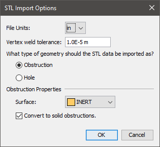
In Figure 28, the following options can be specified:
Because the STL file is simply a listing of triangles, there may be more than one object represented in the file. PyroSim will use the vertex weld tolerance to detect triangle connectivity and determine if there are several, disconnected sets of faces in the file. If there are, there will be one resulting PyroSim object per connected set of faces.
In addition, if the solid option is enabled or the objects are being treated as holes, import will only succeed if each face set is detected as a closed shell by PyroSim.
While PyroSim cannot directly import Autodesk Revit files (RVT), there are several ways to export the data from Revit into a file format that PyroSim can read. Each method has advantages and disadvantages as discussed below.
C:\ProgramData\Autodesk\Revit\Addins\SimLab\FBXExporter\data\Imported_Textures\#Some CAD files contain 2D floor plans, which, on their own, cannot be used in a simulation. These types of files must first be converted into solid 3D geometry. There are two ways in which this can be accomplished.
The first involves using the floor plan as a guide to draw the 3D model. See Drawing in PyroSim for more information.
The second is to convert lines that represent walls into 3D walls using automated tools. This can be done as follows:
This will replace each line with a 3D wall, whose base is centered on the original line.
All FDS calculations are performed within computational meshes. Every object in the simulation (e.g. obstructions and vents) must conform to the mesh. When an object’s location doesn’t exactly conform to a mesh, the object is automatically repositioned during the simulation. Any object that extends beyond the boundary of the physical domain is cut off at the boundary. There is no penalty for defining objects outside of the domain, but these objects do not appear in the Results.
To achieve optimal simulation accuracy, it is important to use mesh cells that are approximately the same size in all three directions.
FDS uses a Poisson solver based on Fast Fourier Transforms (FFTs). A side effect of this approach is that optimal mesh divisions are constrained to the form 2u 3v 5w, where u, v and w are integers. For example, 64 = 26, 72 = 23 * 32, and 108 = 22 * 33 are good mesh dimensions. However, 37, 99 and 109 are not. In addition, using a prime number of cells along an axis may cause undesirable results. PyroSim warns when the number of divisions is not optimal.
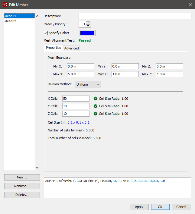
This example illustrates creating a multiple mesh model.
To create the first mesh:
The 3D View will now display the resulting mesh.
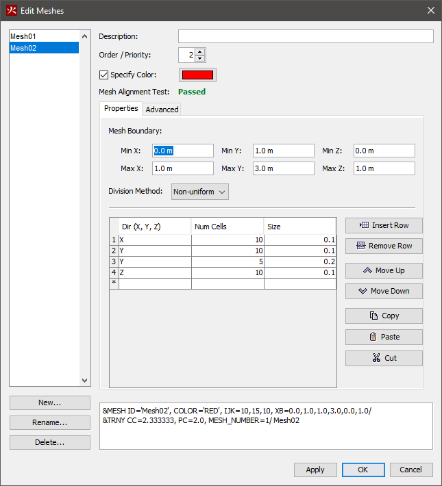
To create a second, nonuniform mesh:
In the table, enter the data shown in Table 2
| Dir (X,Y,Z) | Num Cells | Size |
|---|---|---|
| X | 10 | 0.1 |
| Y | 10 | 0.1 |
| Y | 5 | 0.2 |
| Z | 10 | 0.1 |
You can click ![]() or type Ctrl+R to reset the model.
The resulting meshes are displayed below.
or type Ctrl+R to reset the model.
The resulting meshes are displayed below.
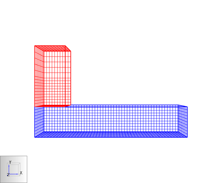
The term "multiple meshes" means that the computational domain consists of more than one rectangular mesh, usually connected, although this is not required. In each mesh, the governing equations can be solved with a time step based on the flow speed within that particular mesh. Some reasons for using multiple meshes include:
Meshes can overlap, abut, or not touch at all. In the last case, essentially two separate calculations are performed with no communication at all between them. Obstructions and vents are entered in terms of the overall coordinate system and need not apply to any one particular mesh. Each mesh checks the coordinates of all the geometric entities and decides whether or not they are to be included.
As described in the FDS User Guide (McGrattan et al. 2021) the following rules of thumb should also be followed when setting up a multiple mesh calculation:
 |  |
 |  |
To simplify working with multiple meshes, PyroSim provides the following additional mesh operations:
To use any of the above actions, select one or more meshes, right-click to open a popup menu, then click the desired mesh action.
To simulate a surface made of heat-conducting solids or a fuel you must specify a material that describes certain thermal properties and pyrolysis behavior. PyroSim offers two categories of materials: solid materials and liquid fuels.
To create a new material, you can use the Edit Materials dialog. On the Model menu, click Edit Materials.
Examples of solid materials include brick, gypsum board, and upholstery. To create a solid material:
After following these steps, a default solid material will be created. Text entered in the Description box will not affect the simulation, but will be preserved in the FDS input file using the FYI field of the material. Including a description of the material is recommended.
The Thermal Properties tab provides the following options:
The Pyrolysis tab provides options to set the heat of combustion and add reactions that will be used to govern how the material burns.
Each material can have a maximum of 10 reactions. To add a reaction, click the Add button. This will open a dialog to edit the new reaction. It provides the following options:
On the Rate tab:
On the Byproducts tab:
Examples of liquid fuels include kerosene and ethanol.
To create a liquid fuel:
After following these steps, a default solid material will be created. Text entered in the Description box will not affect the simulation, but will be preserved in the FDS input file using the FYI field of the material. Including a description of the material is recommended.
The thermal properties tab for liquid fuels is identical to the thermal properties tab for solid fuels, see Solid Materials.
The Pyrolysis tab provides the following parameters:
Surfaces are used to define the properties of solid objects and vents in your FDS model. The surface can use previously defined materials in mixtures or layers. By default, all solid objects and vents are inert, with a temperature that is fixed at the ambient temperature (set in the Simulation Parameters dialog). In addition to defining heat conduction in a solid, surfaces can also be used to define a burner, specify the ignition temperature for an object, give a vent a supply velocity, and set the many other properties supported by FDS.
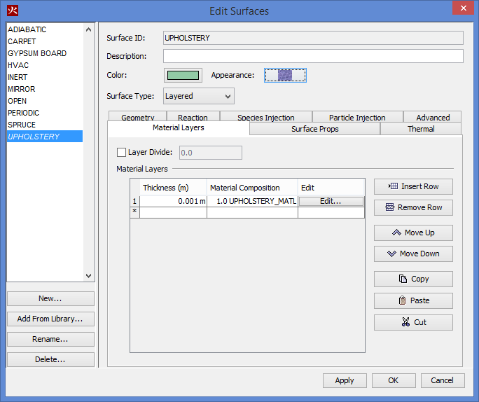
To create, modify, and delete surfaces, you can use the Edit Surfaces dialog. To open the Edit Surfaces dialog, on the Model menu, click Edit Surface Properties. The dialog in Figure 36 shows the dialog being used to edit an upholstery surface.
There are six fundamental or "reserved" surface types: ADIABATIC, INERT, MIRROR, OPEN, HVAC, and PERIODIC. These surfaces cannot be changed and are present in every analysis.
This surface remains fixed at the ambient temperature. Heat transfer does occur from gases to INERT surfaces.
This surface is used only for vents on the exterior mesh boundary. A MIRROR is a no-flux, free-slip boundary that reverses flow. It is intended to be applied to an entire mesh boundary to symmetrically double the size of the domain.
PyroSim aids the user by organizing the surface options into logical types, such as a burner to define a simple fire or a layered surface to represent a solid, heat conducting wall.
There are eight surface types in alphabetical order that you can create in PyroSim.
The Edit Surfaces dialog helps define a surface type with a set of tabs. Each tab provides a collection of input fields and settings for the user to customize that surface type.
Air leak surfaces can be used to create a permeable barrier between two pressure zones, defined by the Leak Path in the Edit Surfaces dialog. The leak area is defined by the zones selected.
This surface type is identical to the built-in INERT surface type. It allows you to customize the description, color, and texture of the inert surface described in Reserved Surfaces.
Tabs: Advanced, Properties (only on this Surface Type)
This surface type represents a fire with a known heat release rate or mass (fuel) loss rate.
Tabs: Advanced, Geometry, Heat Release, Particle Injection, Thermal
Exhaust surfaces can be used to remove gas from the simulation domain. The specification of their air movement parameters is identical to that of a supply surface, but instead of the velocity or flux driving air into the domain, they are pulling air out. Exhaust surfaces do not have the option to apply injection or geometry properties.
The General Surface type is a hybrid between the Burner and Supply surface types. Adding a little more flexibility than either of them individually.
Tabs: Advanced, Air Flow, Geometry, Heat Release, Particle Injection, Species Injection, Thermal
This surface type represents a radiative heat source. The options are identical to the options for a burner without the heat release options. If the surface temperature is less than the ambient temperature, the surface will remove heat from the surrounding gases.
Tabs: Advanced, Geometry, Particle Injection, Thermal
Layered surfaces are composed of one or more material definitions. Materials include solid and liquid substances such as concrete, pine, and ethanol. For more information about materials and how they can be specified in PyroSim, please refer to Materials. This type of surface is ideal for walls and other objects that are composed of real-world materials. This surface type can also be used to inject extra (non-reactive) species into the simulation.
Tabs: Advanced, Geometry, Material Layers, Particle Injection, Reaction, Species Injection, Surface Props, Thermal
This surface represents a vent that injects air into the simulation domain. The temperature of the air injected by supply vents can be controlled using settings on the thermal tab. Species Injection options are available if the Specify Mass Flux of Individual Species option in the Air Flow group is selected and there are extra, non-reactive species present in the simulation.
Tabs: Advanced, Air Flow, Geometry, Particle Injection, Species Injection, Thermal
Each tab of the Edit Surfaces dialog provides a set of inputs and settings that can be used to build a custom surface type as listed in Surface Types. The following sections describe the parameters on each tab and are listed in alphabetical order, not the order they might appear for a surface type.
Sometimes there will not be UI elements in PyroSim for an FDS input parameter that you want to configure. The Advanced tab can be used to enter Additional Fields as Name and Value pairs that will be placed into that specific FDS &SURF record. For more information about custom FDS record input that is not supported by the PyroSim UI, see Advanced Parameters.
The reaction used to model a given surface can either be taken from the material specifications, or given explicitly by the surface. Manually specifying the parameters will produce a surface similar to a burner.
You can edit this behavior using the reaction options:
You can inject extra (non-reactive) species into the simulation using the species injection options. To use these options, you must first specify species using the Edit Species dialog.
You can edit the following species options:
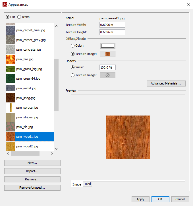
You can add textures to surfaces to increase the realism of your model. This can be done through the use of Appearance objects.
An Appearance defines how the surfaces of objects will appear and can have colors or textures applied to them. Some default appearances are provided or you can import your own. The Room Fire example demonstrates using a wood texture for a pine floor and hanging a picture on a wall. Your textures will be automatically displayed in PyroSim. Appearances will be shown on obstructions and vents when the View Mode is either Realistic or Realistic with Outlines.
To define an appearance with a texture and attach it to a Surface:
Appearances can also be viewed by going to the Model menu and selecting Edit Appearances. This will show the Appearances Dialog.
Appearances can be added manually by clicking New under the appearance list. Newly created appearances are added to the database, and can be used across instances of PyroSim.
Appearances can be deleted by clicking Remove under the appearance list. If the appearance exists in the database, all its associated files in the database directory will also be permanently removed.
The following appearance properties can be edited from this dialog:
Additional appearance properties can be edited by pressing the Advanced Materials button. This will show the Advanced Materials Dialog for the currently selected material.
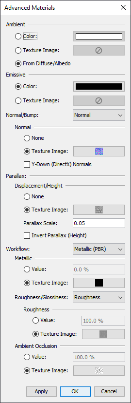
Most properties in this dialog can be specified as either a constant color/value or as a texture image. The following appearance properties can be edited from this dialog:
Depending on which workflow is selected, the following additional properties are provided:
PyroSim provides tools to help the user rapidly create and organize model geometry.
Geometry can either be created through dialogs or by using the drafting tools in the 2D or 3D views as discussed in Drawing in PyroSim.
There are typically three types of geometry that can be created in PyroSim:
The user can also organize the model by creating floors and groups. In addition, the user can assign background images to floors to aid in drafting.
Obstructions are the fundamental geometric representation in FDS. In FDS, obstructions are rectangular, axis-aligned solids defined by two points. Surface properties are assigned to each face of the obstruction. In PyroSim, obstructions can take any shape, have any number of faces, and have different surfaces applied to each face. At the time of simulation, PyroSim will automatically convert the obstructions to axis-aligned blocks required by FDS as discussed in Angled Geometry.
FDS defines two types of obstructions:
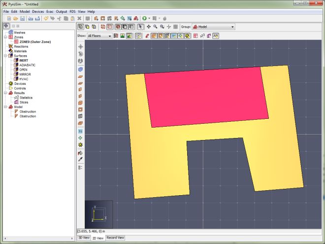
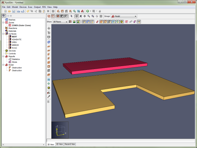
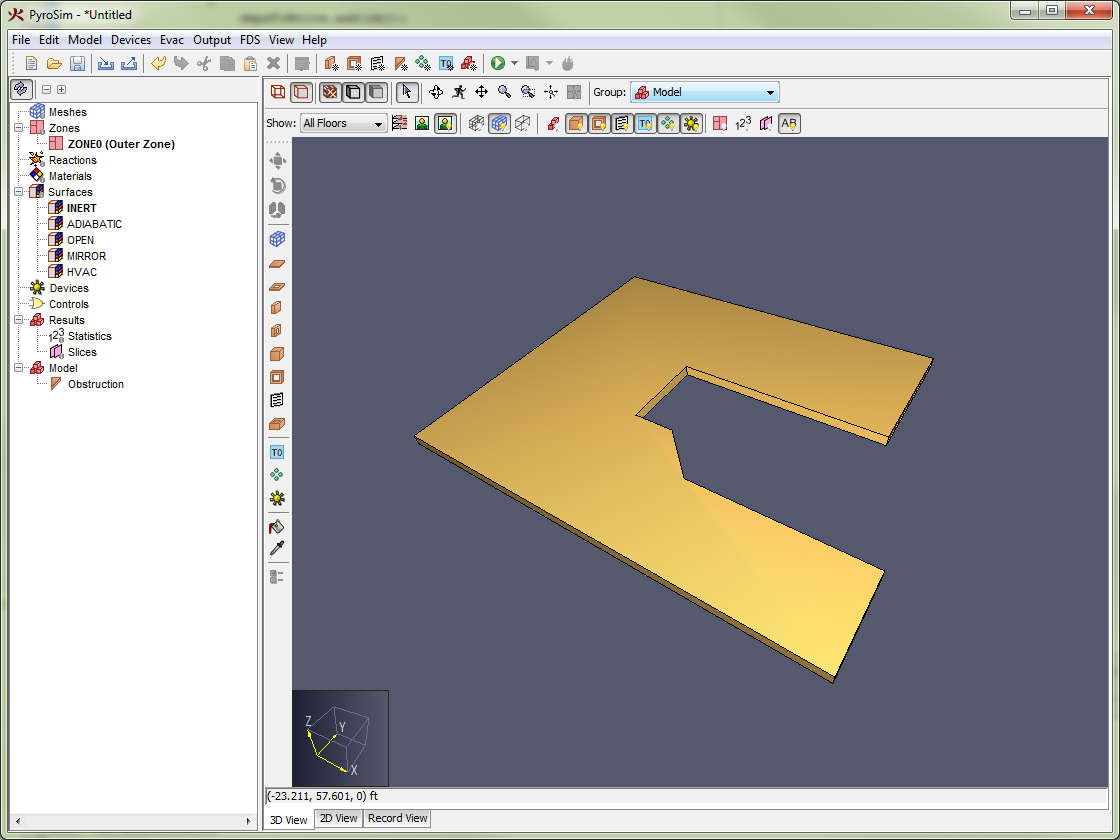
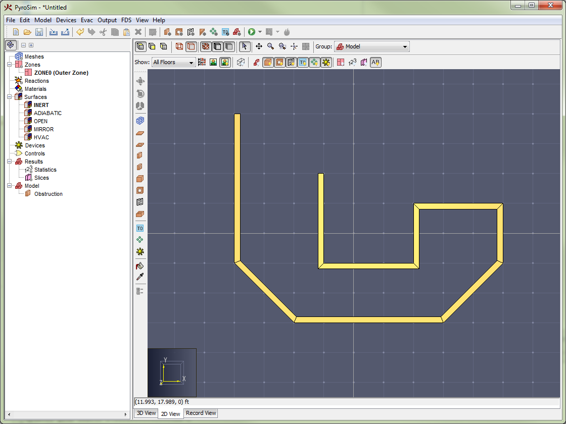
Conversion of a slab obstruction to FDS blocks shows an example of a polygonal slab drawn in PyroSim (Figure 40) and its conversion to blocks for use in FDS (Figure 41).
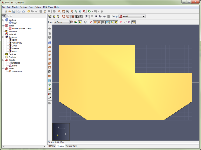 | 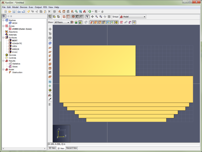 |
To create a new obstruction, either use an obstruction drawing tool as discussed in Drawing in PyroSim or on the Model menu, click New Obstruction. or New Slab.
This tab of the obstruction panel presents all options other than those controlling geometry and surface information. This includes activation events (conditions that can cause the obstruction to be added or removed from the simulation) and miscellaneous options such as color and smoothing.
This tab allows you to enter the min and max coordinates of the object. For more elaborate geometry, such as slabs, this tab may contain a table of points and extrusion options. Extrusion is the mechanism PyroSim uses to extend 2-dimensional objects along a vector - creating a 3-dimensional object.
By default, all six sides of an obstruction use the INERT surface. The Surfaces tab can be used to specify one surface to be used for all six sides of the object or assign surfaces on a per-face basis. Alternately, surfaces can be "painted" using the Paint Tool as discussed in Painting Obstructions and Vents.
Holes are used to carve negative spaces out of obstructions. In FDS, holes are similar to obstructions in that they are defined as axis-aligned blocks. Like obstructions in PyroSim, however, holes can be any shape. PyroSim automatically converts them to blocks in the FDS input file.
PyroSim treats holes as first-class objects that can be selected, deleted, and have other operations performed on them like obstructions as discussed in Working with Geometry Objects.
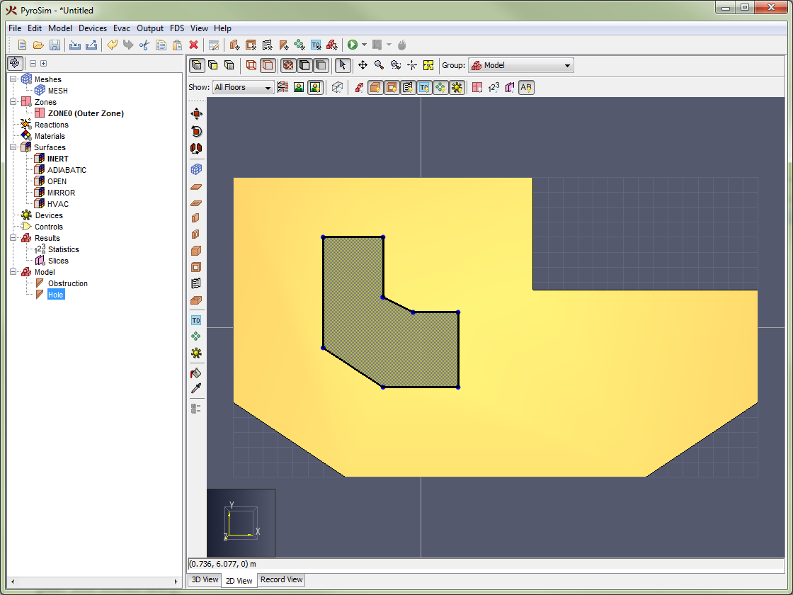
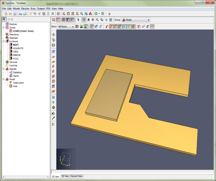
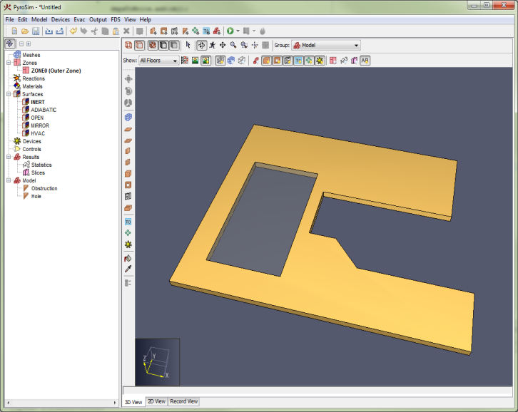
In the 3D and 2D views, holes appear as transparent objects. In addition, for display purposes only, PyroSim carves holes out of obstructions as shown in Figure 43. For complex holes or obstructions or large holes that span many obstructions, this process may be slow. In these cases, hole-cutting display can be turned off by going to the View menu and deselecting Cut Holes From Obstructions.
By default, all obstructions allow holes to be cut from them. To prevent an obstruction from allowing holes, edit the properties of the obstruction as discussed in Obstructions and deselect Permit Holes.
There are various rules that govern how holes are written to the FDS input file. In general, if the PYROGEOM file is enabled, a hole has control logic, and the hole intersects obstructions, the hole will be pre-subtracted from obstructions before the obstructions are converted into blocks, and the holes will be excluded from the FDS file. If the above conditions do not hold, the holes are converted to blocks similarly to obstructions and are written as HOLE records. For more information, see PyroGeom File.
Holes can either be drawn as discussed in Drawing in PyroSim or can be created by opening the Model menu and clicking New Hole.
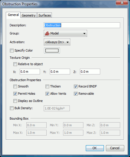
This will open the Hole Properties dialog as shown in Figure 44.
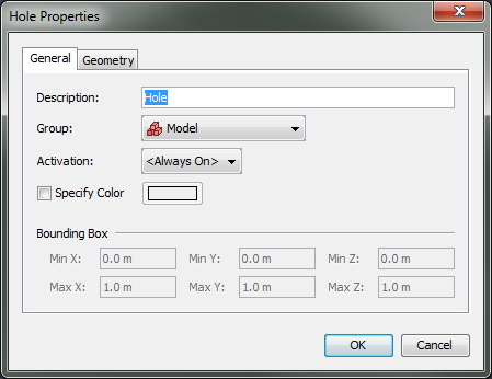
Like obstructions, holes can also be activated as discussed in Control Logic. Holes can also have a color applied.
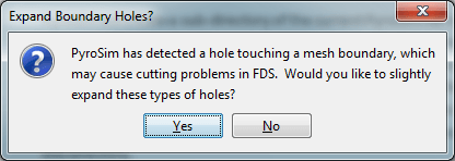
When starting a simulation or exporting an FDS file for some models, the user may receive the following message as shown in Figure 45: "PyroSim has detected a hole touching a mesh boundary, which may cause cutting problems in FDS. Would you like to slightly expand these types of holes?"
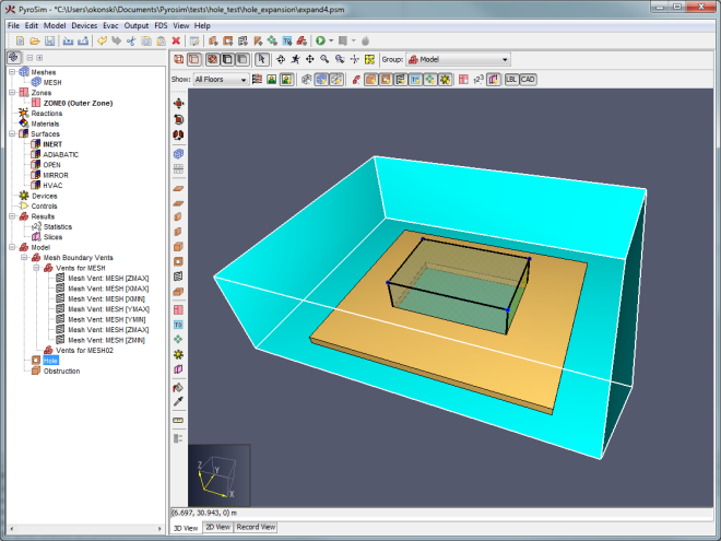
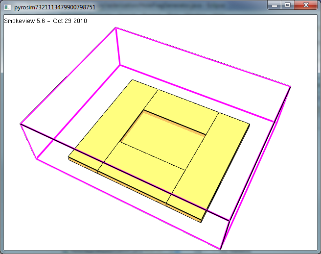
FDS currently has an issue where it will not fully cut a hole from an obstruction if both the hole and obstruction touch a mesh boundary at the same location. Instead, FDS leaves a thin obstruction along the mesh boundary. Figure 46 shows a model in PyroSim that can lead this problem. In this model, both the hole and the obstruction touch the bottom of the mesh, and the hole should cut all the way through the mesh. Figure 47 shows this model in FDS where the hole has not been punched all the way through the obstruction.
PyroSim detects potential cases where this might happen and prompts the user with the Expand Boundary Holes dialog. If the user chooses to expand the hole (the Yes option), PyroSim will expand the hole to 1/10 of a mesh cell past the mesh boundary for every side of the hole that touches a mesh boundary. This ensures the hole is properly cut all the way through the obstruction as shown in Figure 48. If the user chooses not to expand these types of holes (the No option), the hole will be written exactly as specified and may lead to the thin obstruction problem.
 |  |  |
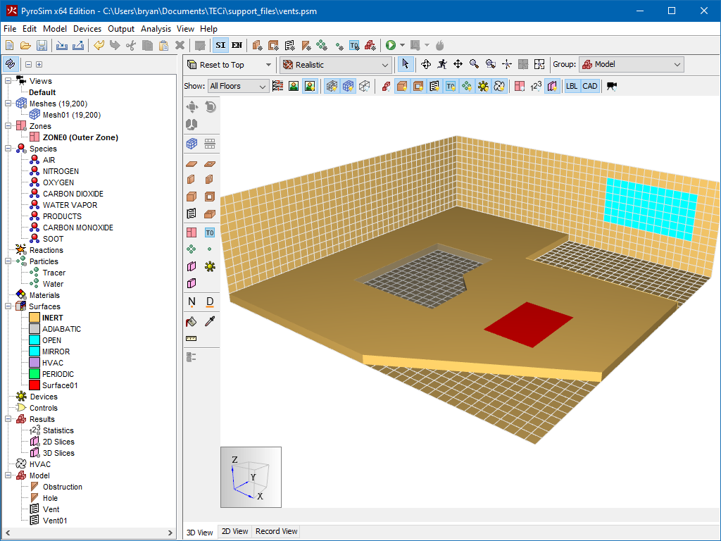
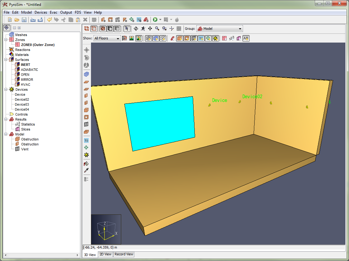
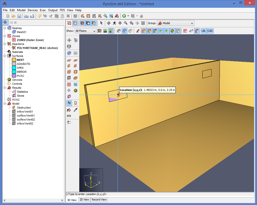
Vents have general usage in FDS to describe a 2D rectangular patch on the surface of a solid obstruction or on a mesh boundary as shown in Figure 49. A vent may have a different surface applied to it than the rest of the obstruction to which it is attached.
Taken literally, a vent can be used to model components of the ventilation system in a building, like a diffuser or a return. In these cases, the vent coordinates form a plane on a solid surface forming the boundary of the duct. No holes need to be created through the solid; it is assumed that air is pushed out of or sucked into duct work within the wall.
You can also use vents as a means of applying a particular boundary condition to a rectangular patch on a solid surface. A fire, for example, is usually created by first generating a solid obstruction and then specifying a vent somewhere on one of the faces of the solid with the characteristics of the thermal and combustion properties of the fuel.
There are two reserved surface types that may be applied to a vent: OPEN and MIRROR. For more information on these types, see Surfaces.
Vents can either be drawn as discussed in Drawing in PyroSim or be created by opening the Model menu and clicking New Vent.
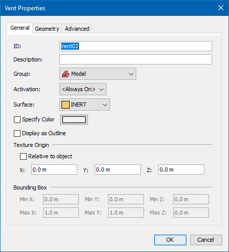
This will open the New Vent dialog as shown in Figure 50. Like obstructions and holes, vents can also be activated, but only if the surface is not MIRROR or OPEN. With the exception of Fire Spread, the other properties are similar to obstructions. Fire Spread can be specified on vents using a burner surface (Surfaces). This option simulates a radially spreading fire at the vent. A vent can also be given radial properties. Defining a Center Point and Radius for a vent will cause FDS to define a vent bounded by the vent’s Bounding Box and the circle generated by the point radius combination.
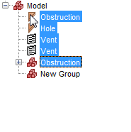
Groups can be used to hierarchically organize the model. Groups can only be seen in the Navigation View. The "Model" is the base group. Users can nest groups inside other groups, allowing the user to work with thousands of objects in an organized way. When the user performs an action on a group, that action will be propagated to all objects in the group.
There are two ways to create a group:
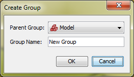
Both of these actions will show the Create Group dialog as shown in Figure 51. This dialog allows the user to choose the parent group and name of the new group.
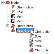
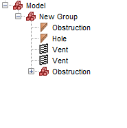
There are several ways to add objects to a group:
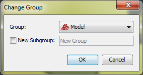
In the Change Group dialog shown in Figure 55, select the desired group. If a new group is desired, select New Subgroup and specify a name. If this is chosen, a new group will be created under the specified existing group, and the selected objects will be moved to this new group. * For newly drawn objects, in the 3D or 2D view select the desired group from the group drop-down above the view as shown in Figure 56. All newly drawn objects will be added to this group.
 |  |  |

Floors are used in PyroSim to quickly apply clipping filters to the scene to only show a portion of the model. They are also used to initialize the properties of drawing tools so that they draw at the proper Z location.
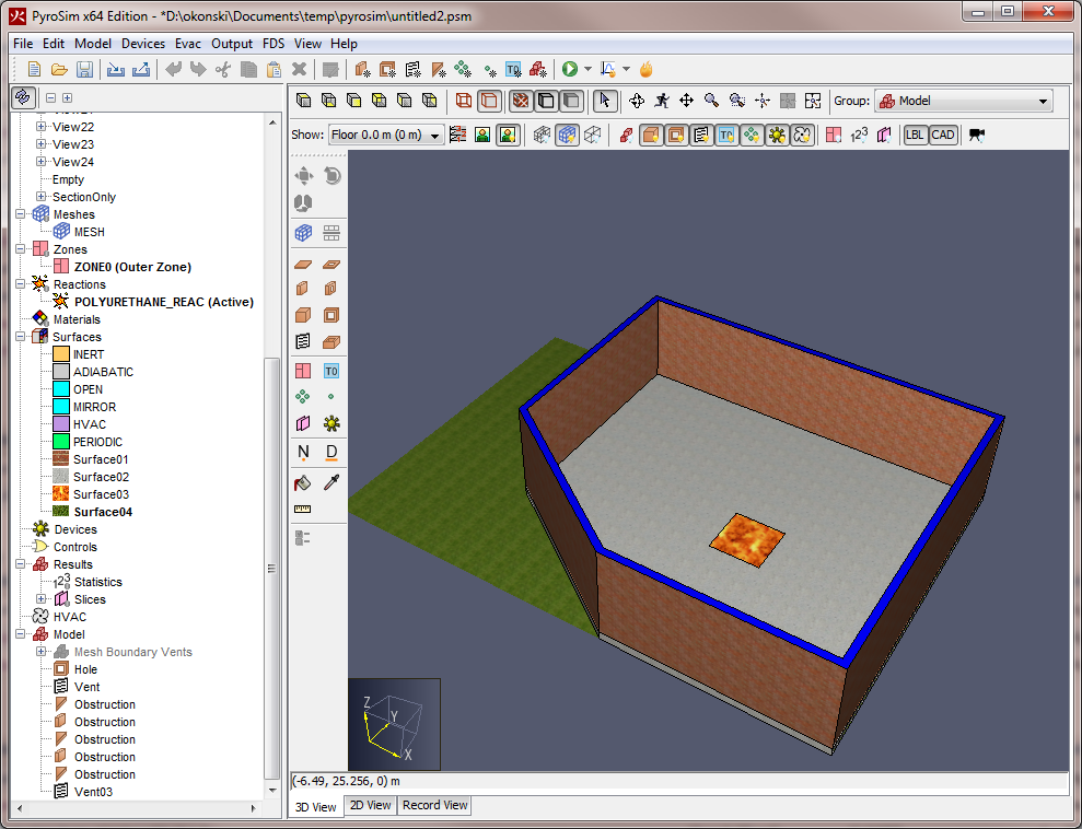
An example of floor clipping is shown in Floor clipping, where Figure 57 shows all floors and Figure 58 shows a single floor.
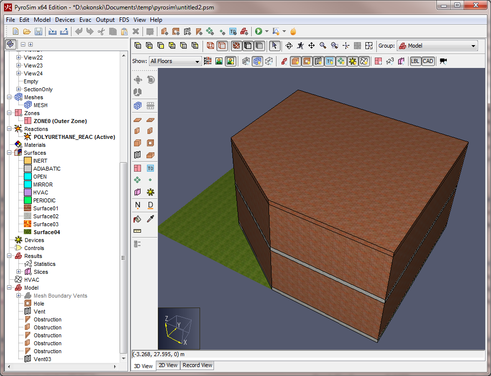 |  |
To define the floors in a model, go to the 2D or 3D View and click the Define Floor Locations button (![]() ).
This will display the Manage Floors dialog shown in Figure 59.
).
This will display the Manage Floors dialog shown in Figure 59.
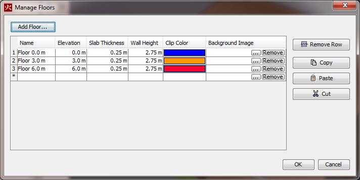
Floors are defined by the following properties:
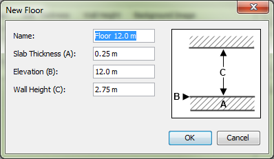
To add a new floor, click the Add Floor. button at the top of the Manage Floors dialog. This will show the New Floor dialog shown in Figure 60. By default this dialog will assume the user wants a floor above the previous floor using that floor’s slab thickness and wall height properties. In this dialog, if the user enters a new slab thickness, the elevation will be automatically updated so the new floor does not overlap the others unless the user enters a specific value for the elevation. In addition, unless the user enters a specific name, a name will be automatically generated based on the elevation.
Press OK to create the new floor.
Press OK again in the Manage Floors dialog to commit the changes.
By default, the model contains one floor at elevation 0.0 m with a slab thickness of .25 m and a wall height of 2.75 m. Using these values leaves a distance of 3.0 m from one floor elevation to another.
Once the floors have been defined, the user can filter the display to show either a single floor or all floors as shown in Figure 7. For most views, the Z clipping range for a particular floor is from the floor elevation minus slab thickness to floor elevation plus wall height. The Z clipping range works differently for the top camera of the 2D view, however. In this view, the clipping is from the elevation of the floor BELOW to the elevation plus wall height of the current floor. This allows the geometry on the floor below to be snapped to in drawing geometry for the current floor. For this to be useful, however, the user may want to use wireframe rendering.
Quickly define floors by selecting some geometry, right-click the selection, and choose the Add Floor to Fit Objects item in the context menu. This will automatically add a floor in the Manage Floors dialog with values based upon the selected geometry.
See Figure 60 for an illustration of the information below.
Each floor can have an associated background image.
To add a background image to a floor, go to the 2D or 3D View, select a specific floor, then click the Configure Background Image button (![]() ).
Alternately click the Define Floor Locations button, (
).
Alternately click the Define Floor Locations button, (![]() ), and then in the Background Image column, select the Edit button.
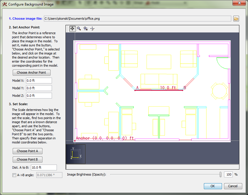
This will display the Configure Background Image dialog shown in Figure 61.
), and then in the Background Image column, select the Edit button.
This will display the Configure Background Image dialog shown in Figure 61.
You will be guided through the following steps:
Now, in the 3D or 2D views, when the user displays a specific floor, the background image for that floor will be displayed.
To turn off the background images, go to the 2D or 3D View, and click the Show Background Images button (![]() ) next to the floors drop-down.
) next to the floors drop-down.
While not a full-fledged drafting application, PyroSim does provide useful drawing features, including the following:
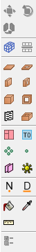
PyroSim provides several drawing and editing tools. These tools are located on the drawing toolbar at the left side of the 3D and 2D Views as shown in Figure 62.
Some of these tools allow a user to create and edit objects such as slabs and walls that are not constrained to the FDS mesh.
In these cases, PyroSim will automatically convert the shapes to mesh-based blocks when the FDS input file is created.
These blocks can be previewed by clicking the Preview FDS Blocks button (![]() ) on the filter toolbar above the 3D or 2D View.
For information on block conversion, see Angled Geometry.
) on the filter toolbar above the 3D or 2D View.
For information on block conversion, see Angled Geometry.
To begin drawing or editing with a tool, the user can single-click the tool from the tool bar. Once the tool has finished drawing/editing its object, the last-used navigation tool is automatically selected.
If the user would like to create several objects with the same tool in succession, the desired tool can be pinned by clicking the tool’s button twice.
The button will show a green dot when pinned (![]() ).
).
Every time the same tool button is clicked, the pinned state of that tool will be toggled, so clicking the button again after pinning will disable pinning (![]() ).
).
At any time, the current drawing/editing tool can be cancelled by pressing ESC on the keyboard. This will also cancel pinning and will revert back to the last-used navigation tool.
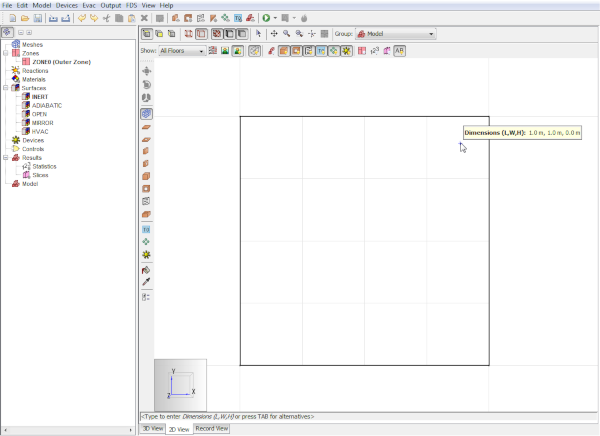
Most drawing/editing tools require at least two points to be specified to complete its action, such as drawing the points for a wall or defining the extents of a box.
These tools can operate in two modes:
Each tool has a set of properties that can be modified by clicking the Tool Properties (![]() ) button located at the bottom of the toolbar after selecting the desired tool.
Options such as elevation, height, surface, and color can all be edited in the Tool Properties dialog.
) button located at the bottom of the toolbar after selecting the desired tool.
Options such as elevation, height, surface, and color can all be edited in the Tool Properties dialog.
In addition to the tool properties, each tool also has additional quick actions. To show these actions, start the desired tool and then right-click in the 2D or 3D View. This opens a context menu with the quick actions. Figure 63 shows an example of the quick action menu for the wall tool.
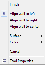
This menu allows the user to perform actions specific to the tool, such as closing a polygon, picking a surface, setting wall alignment, accessing the tool properties, etc.
Snapping is one way to precisely draw and edit objects. It is the process of finding some element in the scene, such as a vertex or edge close to the cursor, and snapping the cursor to that element like a magnet.
In PyroSim, snapping can be performed against the solution meshes, objects in the model, and orthographic constraints. The 2D View additionally provides a sketch grid and polar (angle) constraints. If a snap point is found, an indicator dot shown in Figure 64 will appear at the snap point.
By default, snapping is enabled. It can be disabled by holding ALT on the keyboard while using a drawing/editing tool.
If there are any solution meshes in the model (see Meshes), PyroSim can snap to them during drawing and editing. For each mesh that is visible, PyroSim can snap to its boundary edges, boundary faces, grid lines, and the intersections of the grid lines, depending on which mesh display filters are active as discussed in Filtering.
PyroSim also provides a user-defined drawing grid, or sketch grid, in the 2D View as shown in Figure 65.
When a new model is created, the sketch grid is visible and can be snapped to in the 2D view. The default spacing for the divisions is 1 m, but can be changed by going to the View menu and clicking Set Sketch Grid Spacing.
Once the user has created a solution mesh, PyroSim will automatically switch to solution mesh snapping and disable sketch grid snapping. In the 2D View, PyroSim will only snap to the sketch grid or visible solution meshes. To switch which snapping is being used, on the View menu choose Snap to Sketch Grid or Snap to Model Grids. To disable grid snapping altogether, on the View menu choose Disable Grid Snapping.
All objects displayed in the model can be snapped to when using the drawing/editing tools. There are three basic categories of geometry that can be snapped to on objects: faces, edges, and vertices. Objects can have any combination of types. If there are multiple types close to the cursor, PyroSim will give vertices precedence over edges and edges precedence over faces.
Constraints are dynamic snapping lines that are only visible when the cursor is near them. They appear as infinite dotted lines as shown in Figure 66.
PyroSim contains two types of constraints:
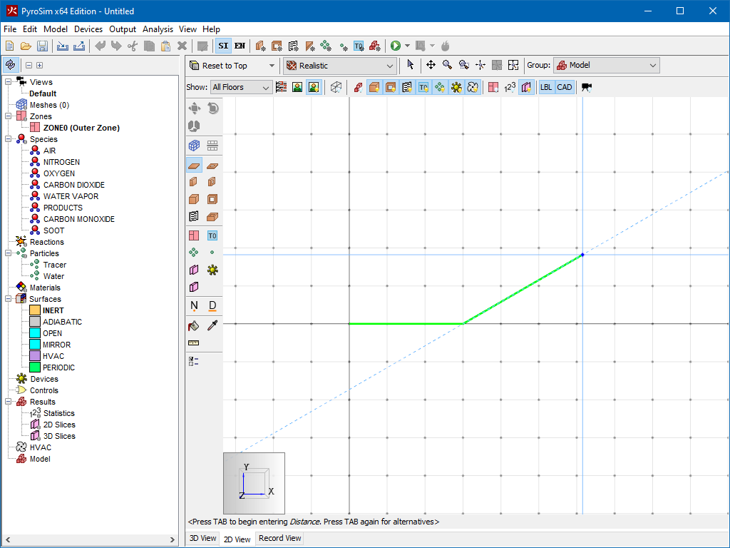
If a constraint is currently being snapped to, that constraint can be locked by holding SHIFT on the keyboard. While holding SHIFT, a second dotted line will extend from the cursor to the locked constraint (the first dotted line). This is useful for lining up objects along a constraint with other objects.
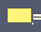
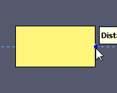
For instance, in Figure 67, a box already exists in the model. A second slab is being drawn such that the third point of the slab lines up with the right side of the first box. This was done as follows:
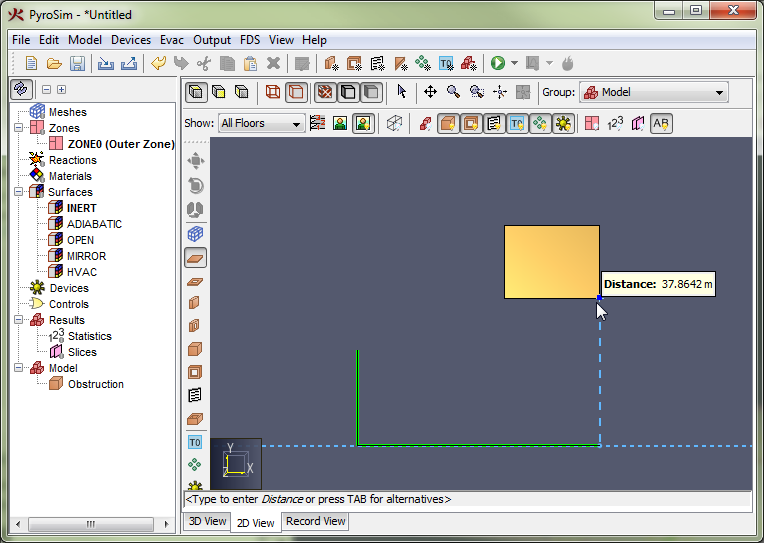
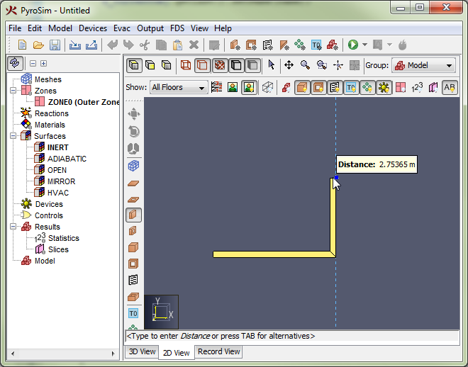
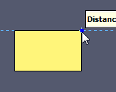
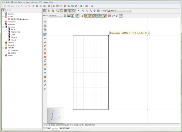
While using a drawing/editing tool, a popup window may appear next to the cursor, such as in Figure 68. This window shows the value used to determine the next point or value for the current tool. In this figure the value is the Distance from the previous point along the vector from the previous point to the current cursor location. For other tools, this value may be angle or relative offset, etc.
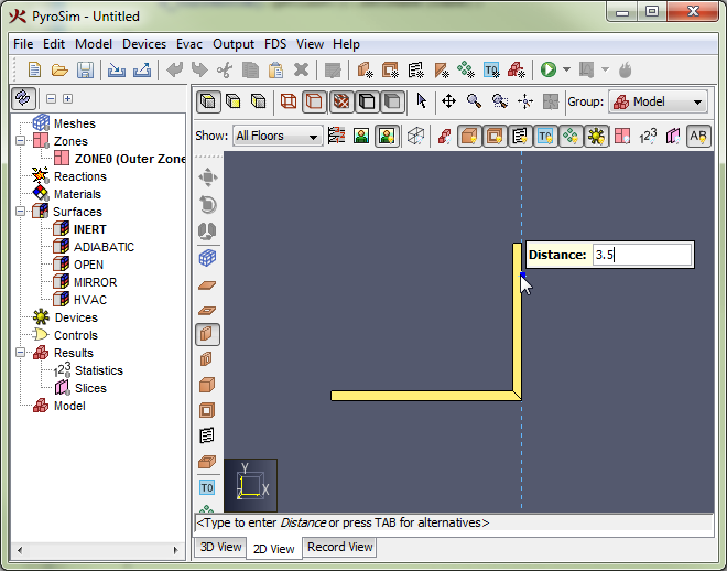
The value is editable if the status bar at the bottom of the 3D or 2D View indicates it is. For instance, in the figure, the status bar says "<Type to enter Distance or press TAB for alternatives>". If the user starts typing, the popup window will be replaced with an editing window as shown in Figure 69. If the user presses ENTER, the typed value will be committed. If the user presses ESC instead, the keyboard entry will be cancelled.
Pressing TAB cycles through alternate input methods to determine the next value. For instance, pressing TAB with the wall tool allows the user to enter a relative offset from the last point instead of a distance. Pressing TAB a second time allows the user to enter an absolute position for the next point, and pressing TAB a third time will cycle back to the distance input.
Precise keyboard entry may be easiest for some users when using the multi-click mode of drawing rather than using the click-drag mode. Using multi-click allows both hands to be used to type as opposed to click-drag, which requires one hand to remain on the mouse.
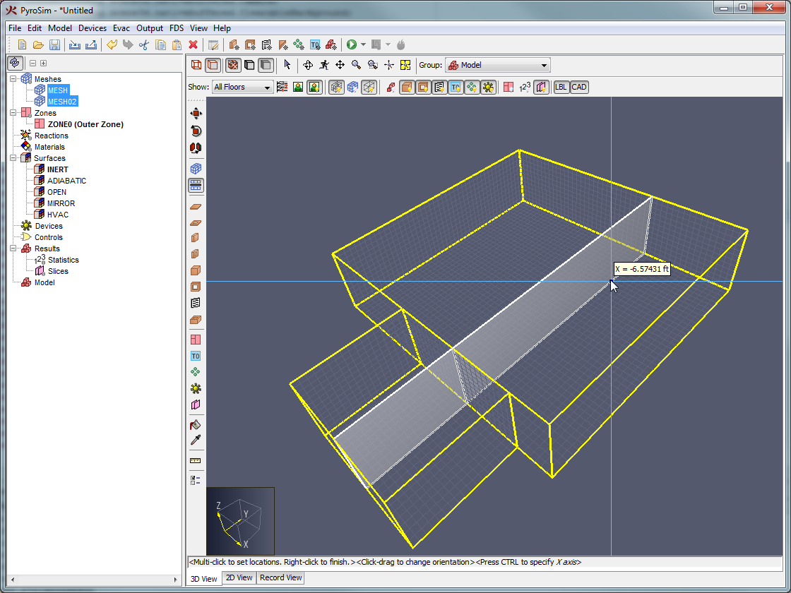
There are some key differences between drawing in the 2D and 3D Views. The 2D View is useful when drawing should be restricted to one pre-defined plane. It is also useful for lining up objects along the X, Y, or Z axes. The 3D View is useful when an object such as a vent or solid-phase device needs to be snapped to the face of an obstruction or vent or if the user would like to build objects by stacking them on top of one another.
When drawing in the 2D View, the drawing will always take place in the drawing plane specified in the tool properties, and snapping is only performed in the local X and Y dimensions. The local Z value will remain true to the drawing plane. In addition, if a tool has some sort of height or depth property, the tool will also remain true to that value. Slabs in different planes aligned in the 2D View shows two slabs that have been drawn in the top view (Figure 70), one at Z = 0 m and the other at Z = 1.5 m. While snapping was used to partially align the objects, they both remain in the Z planes specified in their tool properties shown in the rotated view (Figure 71).
 |  |
The 3D View uses snapping in all three dimensions, causing tool properties to be interpreted more loosely. The drawing plane and depth properties for a drawn object are context-sensitive in the 3D View. When using tools such as the slab tool, the first clicked point determines the drawing plane. If, on this first click, another object is snapped to, the drawing plane is set at the Z location of that snap point. The tool properties' drawing plane is only used if nothing is snapped to on the first click.
This 3D snapping feature of the 3D View is useful for drawing vents on obstructions and attaching solid-phase devices to obstructions as shown in Figure 72.
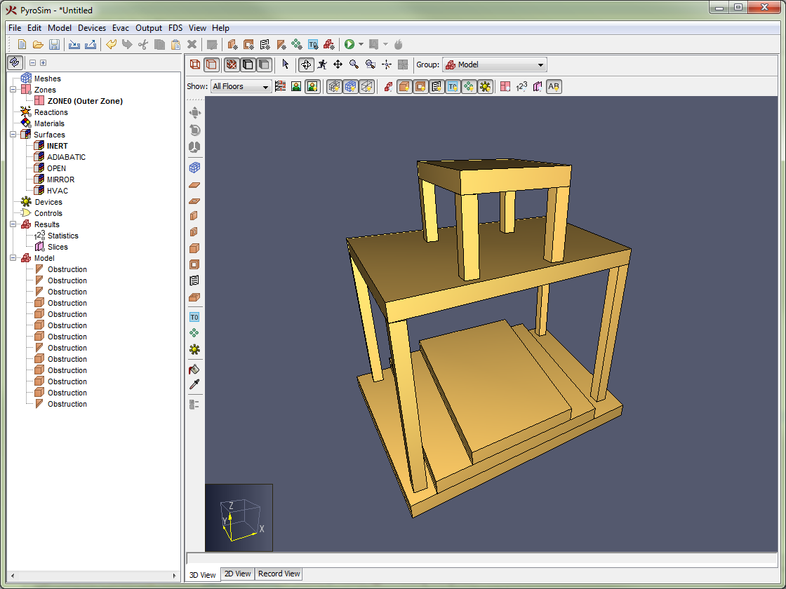
The 3D snapping feature is also useful for stacking objects, as shown in Figure 73. In this figure, the drawing plane was never changed. All the objects were stacked on top of each other using snapping.
While stacking can be useful for obstructions, a user must be more careful when drawing holes in the 3D View. For instance, with the slab hole tool and block hole tool, the user will need to change the extrusion direction to properly direct the hole into the obstruction.
For instance, if the user draws a slab obstruction in the 3D View and then draws a slab hole while snapping to the obstruction, the hole will be stacked on top of the obstruction without cutting a hole as shown in Figure 74.
To draw this properly, the user would need to change the extrusion direction when drawing the hole by pressing CTRL on the keyboard or changing it through the tool’s right-click menu. This will result in a proper hole as shown in Figure 75.
This is not a problem in the 2D View since it always uses the drawing plane set in the tool properties instead of stacking the objects.
 |  |
Once the drawing plane for a tool has been established by the first click, the tool can still determine the next points by snapping to objects in another plane. In this case, the snapped points will be projected to the drawing plane for the current tool. A dotted line will show how the snapped point was projected to the plane. For instance, Figure 76 shows a new slab being drawn in the Z = 1.5 plane. A slab below the new slab is being snapped to determine the new slab’s points.
There are four tools that can draw obstructions, for more information on obstructions, see Obstructions.
![]() Slab Obstruction Tool: Used to draw the slab for a floor.
Slab Obstruction Tool: Used to draw the slab for a floor.
![]() Wall Obstruction Tool: Used to draw a wall.
Wall Obstruction Tool: Used to draw a wall.
![]() Block Obstruction Tool: Used to fill grid cells with obstructions.
Block Obstruction Tool: Used to fill grid cells with obstructions.
![]() Room Tool: Used to draw a rectangular room
Room Tool: Used to draw a rectangular room
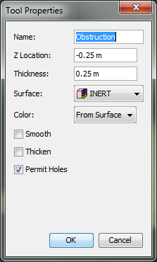
For all the obstruction tools, the tool properties dialog (![]() ) will appear similar to that in Figure 77.
The only section of the dialog that will change between these tools is the geometry, such as Z Location and Thickness.
All other properties, including name, surface, color, and obstruction flags appear in all obstruction dialogs.
These parameters control the properties that will be applied to the next drawn obstruction.
) will appear similar to that in Figure 77.
The only section of the dialog that will change between these tools is the geometry, such as Z Location and Thickness.
All other properties, including name, surface, color, and obstruction flags appear in all obstruction dialogs.
These parameters control the properties that will be applied to the next drawn obstruction.
The surface and color of the next obstruction can also be set via the right-click menu for the tool.
A slab is an extruded polygonal object as shown in Figure 78 that can be used to draw the slab for a floor in a building.
The slab obstruction tool ![]() adds two additional properties to the tool dialog for obstructions:
adds two additional properties to the tool dialog for obstructions:
To draw the polygon vertices of the slab obstruction, perform the following:
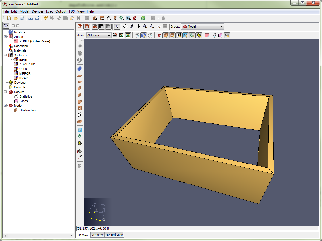
The wall obstruction tool (![]() ) can be used to draw multi-segmented walls as shown in Figure 79.
In this figure, there is only one wall.
The user specifies a path along the floor from which the wall is extruded up.
The wall can be aligned to the left, right, or center of the drawn path.
) can be used to draw multi-segmented walls as shown in Figure 79.
In this figure, there is only one wall.
The user specifies a path along the floor from which the wall is extruded up.
The wall can be aligned to the left, right, or center of the drawn path.
The wall obstruction tool adds three properties to the tool properties dialog:
The alignment of the wall can be controlled through the right-click menu for the tool or can be cycled by pressing the CTRL key on the keyboard. The alignment options are Left (Figure 80), Center (Figure 81) and Right (Figure 82) as shown in Wall alignment options.
 |  |  |
To draw a wall, perform the following steps:
If the first clicked point is clicked again after drawing at least two segments or Close is chosen from the right-click menu, the tool will draw one last segment from the last clicked point to the first point and finish. Alternately, the wall can be ended at the last clicked point by choosing Finish from the right-click menu.
The Block Obstruction Tool (![]() ) can be used to quickly fill grid cells with blocks as shown in Figure 83 or place a block with a single click.
) can be used to quickly fill grid cells with blocks as shown in Figure 83 or place a block with a single click.
This tool adds the following properties to the tool properties dialog:
In addition, the extrusion direction for the block can be toggled by pressing CTRL on the keyboard or through the right-click menu for the tool.
To create blocks using this tool, perform the following:
The Room Tool (![]() ) can be used to draw a rectangular room using one closed wall as shown in Figure 84.
) can be used to draw a rectangular room using one closed wall as shown in Figure 84.
The room tool contains the same properties as the wall obstruction tool.
To draw a room with the room tool perform the following:
There are three tools that can draw holes, for more information on holes, see Holes.
![]() Slab Hole Tool: Used to draw a hole in a floor slab.
Slab Hole Tool: Used to draw a hole in a floor slab.
![]() Wall Hole Tool: Used to draw an opening in a wall, such as for a doorway or window.
Wall Hole Tool: Used to draw an opening in a wall, such as for a doorway or window.
![]() Block Hole Tool: Used to fill grid cells with holes.
Block Hole Tool: Used to fill grid cells with holes.
All these tools work the same as their obstruction counterparts, but they do not have the properties specific to obstructions, such as the surface or obstruction flags.
There is only one tool for drawing vents (for more information on vents, see Vents). PyroSim only allows vents in an X, Y, or Z plane. Vents cannot currently be drawn off-axis like walls can.
Vents also must be attached to solid obstructions (at least one grid cell thick). This is easily accomplished by drawing the vent in the 3D View (see 2D versus 3D Drawing).
To draw a vent, perform the following:
Solution meshes can also be drawn in PyroSim with the Solution Mesh Tool (![]() ) as shown in Figure 85.
) as shown in Figure 85.
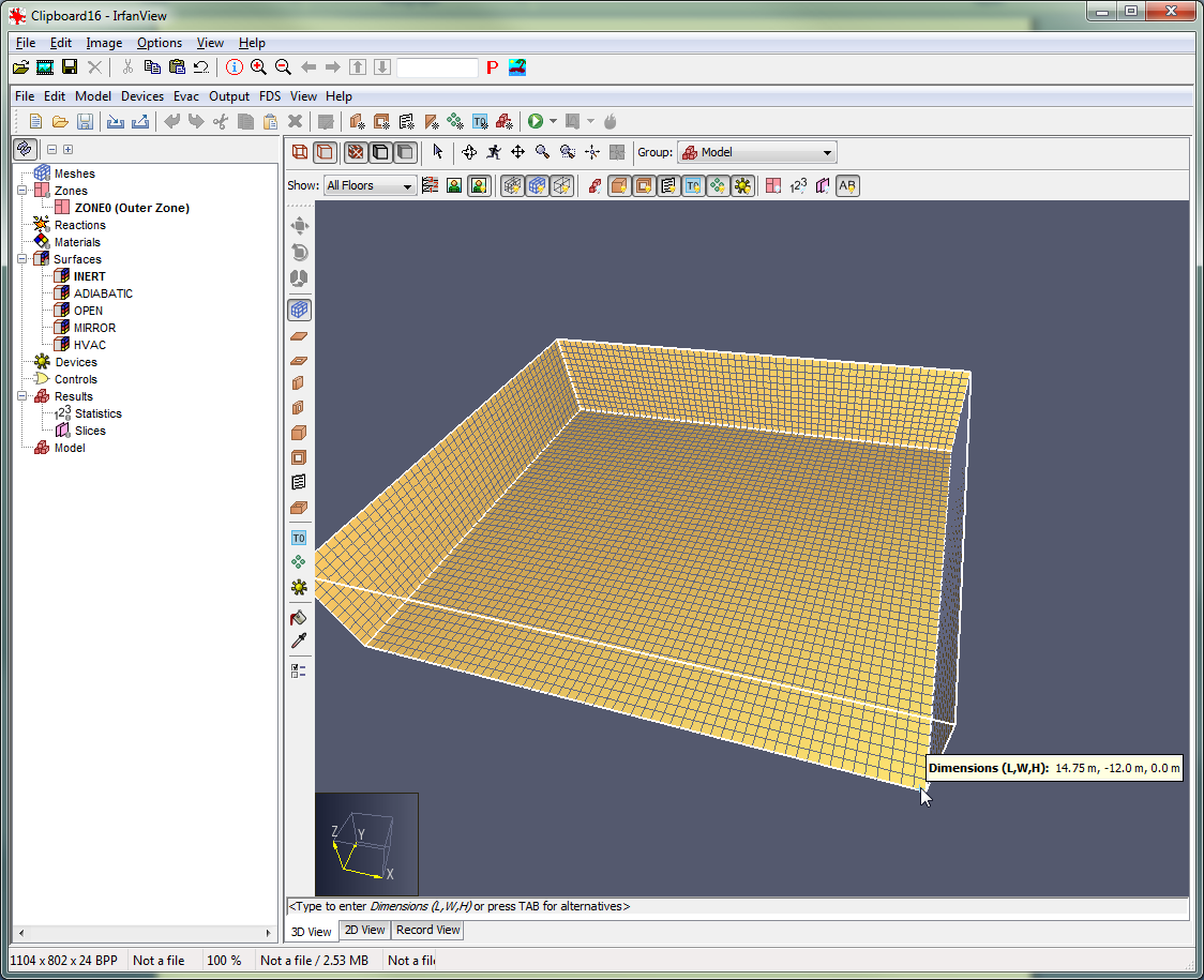
The solution mesh tool has the following tool properties:
 |  |
To draw a solution mesh, perform the following:
Solution meshes can be easily split into two or more sub-meshes by using the Mesh Splitter Tool (![]() ).
).
To split one or more meshes, perform the following:
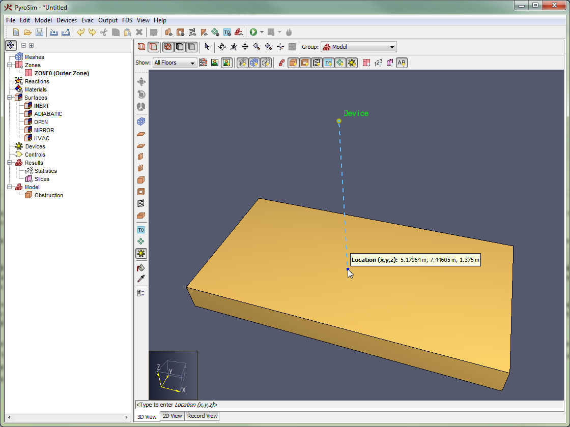
PyroSim allows point devices to be drawn with the Device Tool (![]() ), for more information on devices, Devices.
), for more information on devices, Devices.
The device tool has the following properties:
To draw a device, perform the following:
If it is a solid-phase device, the device’s location will snap directly to the point under the cursor if one is found. This makes it trivial to attach a solid-phase device to an obstruction. If the device is a gas-phase device, however, the device’s location will be projected to the plane as set in the device tool properties as shown in Figure 89. This makes it easy to draw devices at a specific height above the floor. This behavior can be overridden for either type of device by selecting Lock Z to [V] (where V is the drawing plane) or Lock Z to Snap Location in the tool’s right-click menu. Lock Z to [V] is the automatic behavior for gas-phase devices and Lock Z to Snap Location is the automatic behavior for solid-phase devices.
Planar slices, as discussed in 2D Slices can be drawn with the planar slice tool (![]() ).
).
To do so, perform the following:
The slice plane can be changed through the right-click menu, by click-dragging the left mouse button, or by pressing CTRL on the keyboard to cycle through the options.
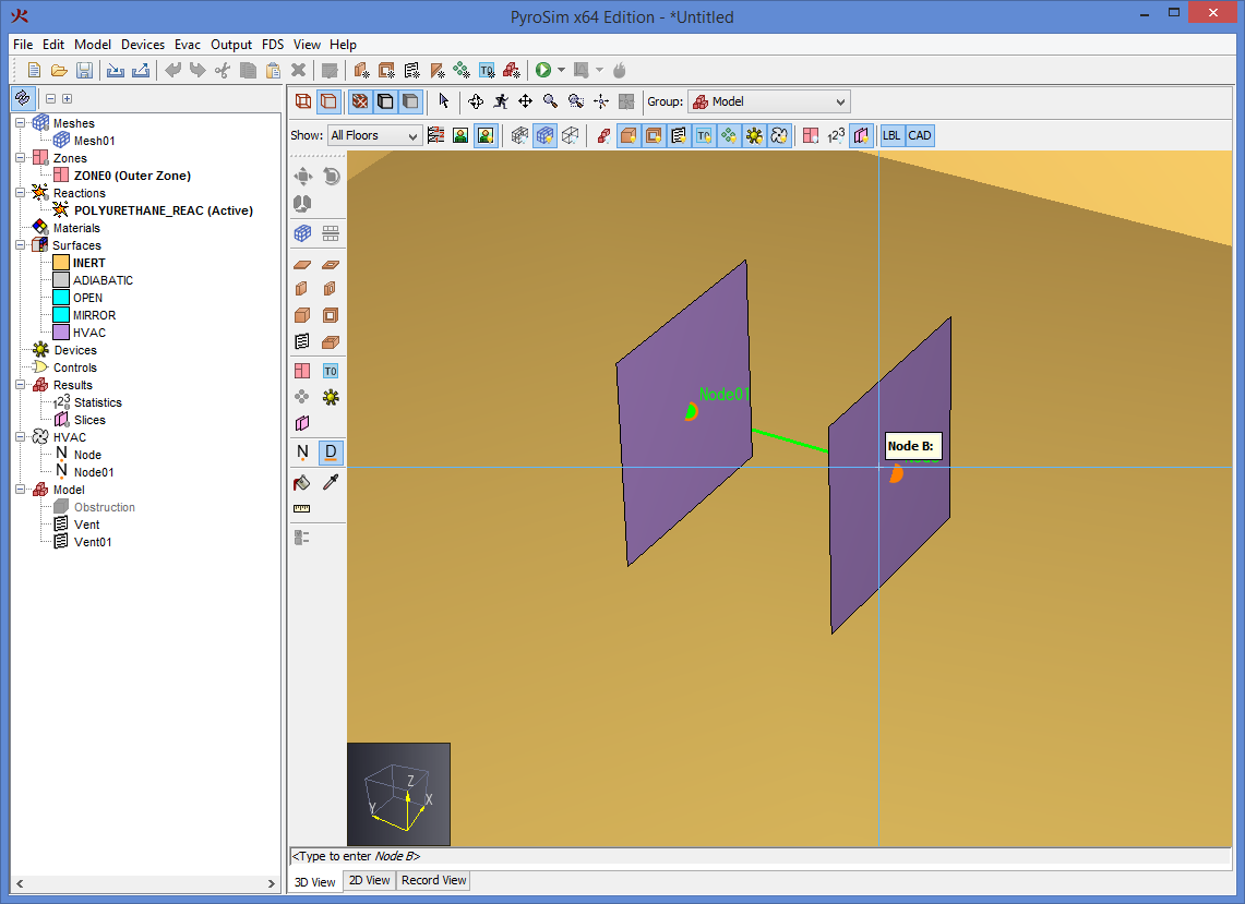
HVAC nodes as discussed in HVAC Node, can be drawn with the HVAC Node Tool (![]() ).
).
To do so, perform the following:
PyroSim allows HVAC ducts to be drawn with the HVAC Duct Tool (![]() ).
).
To do so, perform the following:
PyroSim can also be used to draw:
![]() Init Regions (Init Regions) with the Init Region Tool.
Init Regions (Init Regions) with the Init Region Tool.
![]() Particle Clouds (Particle Clouds) with the Particle Cloud Tool.
Particle Clouds (Particle Clouds) with the Particle Cloud Tool.
![]() Single Particles (Particles) with the Particles at a Point Tool.
Single Particles (Particles) with the Particles at a Point Tool.
![]() 3D Slices (3D Slices) with the 3D Slices tool.
3D Slices (3D Slices) with the 3D Slices tool.
![]() Pressure Zones with the with the Zone Tool.
Pressure Zones with the with the Zone Tool.
These tools draw axis-aligned boxes, and so they behave similarly. They all have the following drawing properties:
To draw one of these objects, perform the following:
Nearly all geometric objects can also be graphically edited in the 3D or 2D View with the Select/Manipulate Tool (![]() ).
).
Editing is performed through an object’s editing handles. Handles appear on an object either as a blue dot as shown in Figure 93 or a face with a different color. The dots indicate a point that can be moved in either two or three dimensions. A discolored face indicates that a face can be moved or extruded along a line.
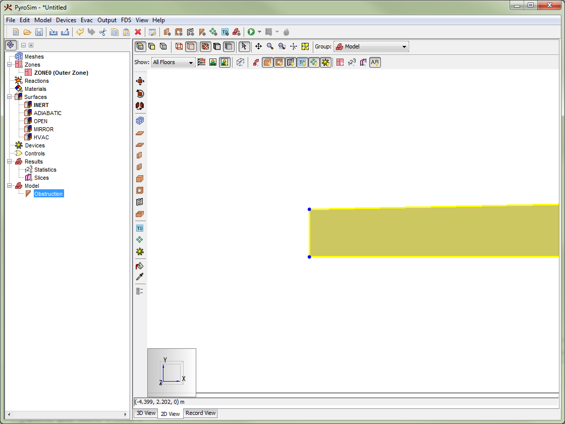
To graphically edit an object, perform the following:
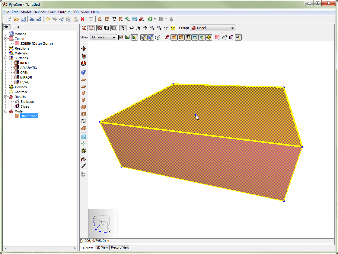
PyroSim provides a variety of tools to transform geometry objects. With the transform tools, users can move, rotate, and mirror objects.
Each tool has an alternate mode to copy the source objects with the transform. To toggle copy mode on/off, press the CTRL key on the keyboard. Alternately, choose Copy Mode or Move Mode from the tool’s right-click menu. When using copy mode, the selected objects are copied and the copies are transformed.
This tool allows the user to move selected objects to a new location as shown in Figure 95, or to create and move a copy of the selected objects.
To use this tool, perform the following:
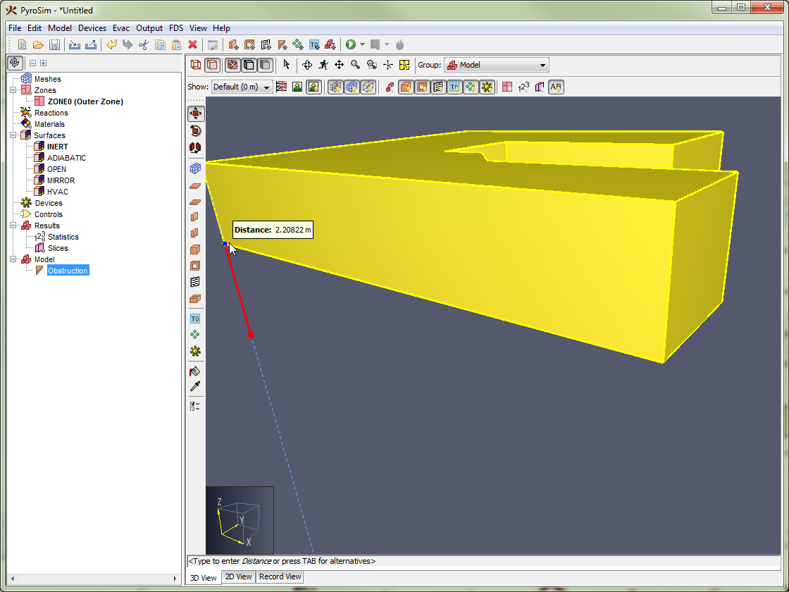
This tool allows the user to rotate selected objects as shown in Rotating an object with the Rotate Tool, or to create and rotate a copy of the selected objects.
To use this tool, perform the following:
The selected objects will be rotated by the angle between the reference and angle vectors.
The following defines the axis about which objects are rotated for each view:
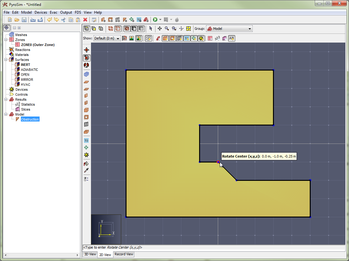 | 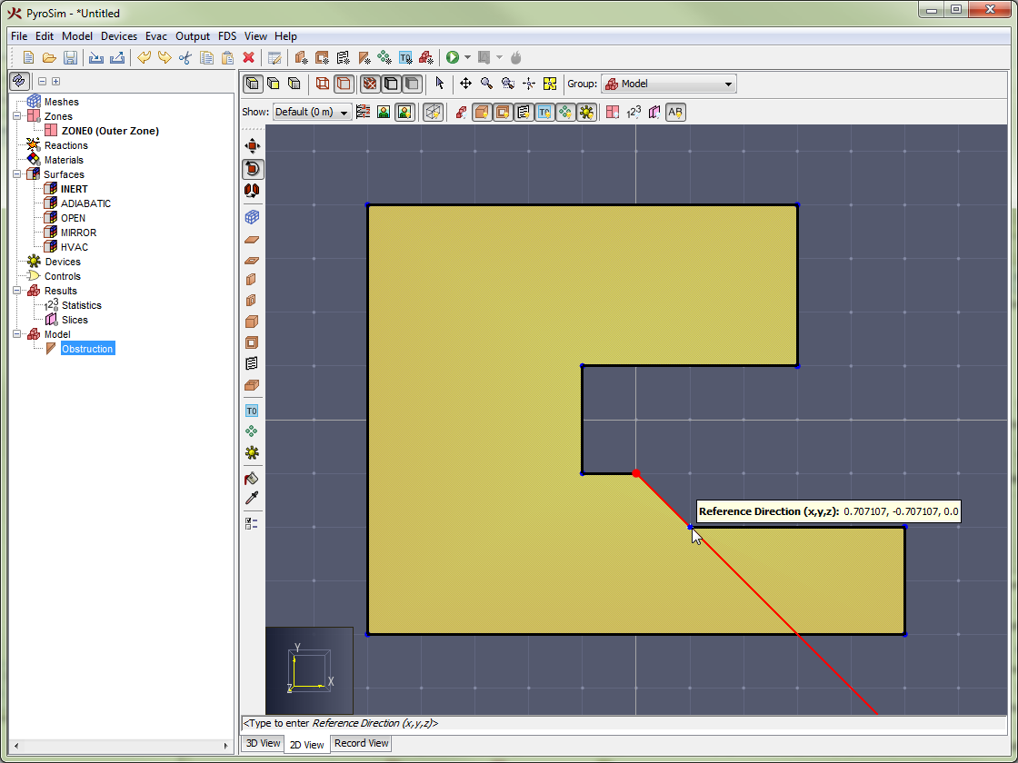 | 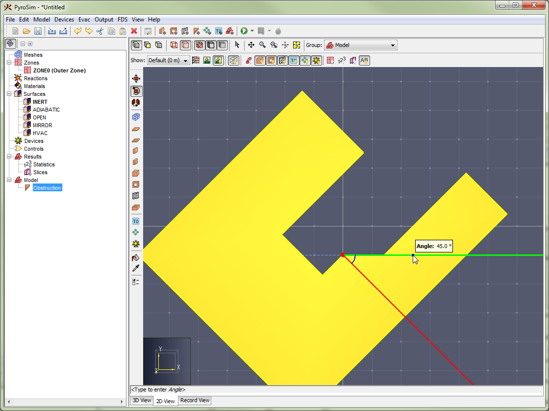 |
The mirror tool allows selected objects to be mirrored across a plane as shown in Mirroring an object using the Mirror Tool, or to create a mirrored copy of the selected objects.
To use the mirror tool, perform the following:
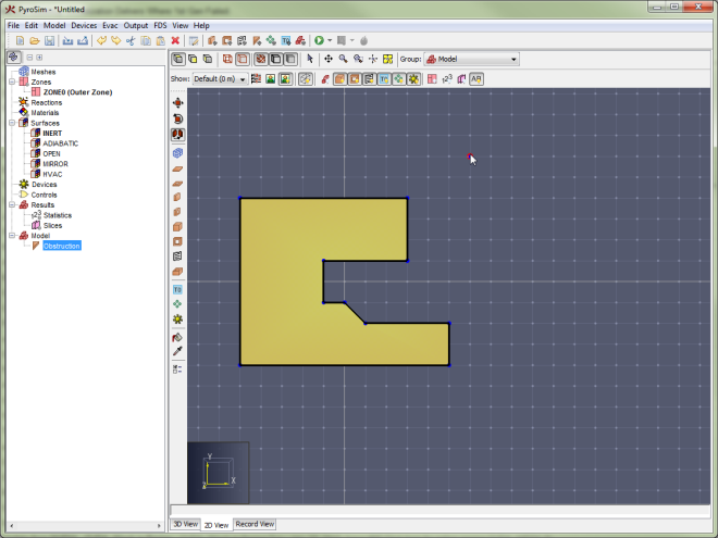 | 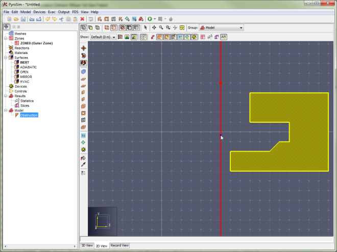 |
PyroSim provides tools to paint obstructions and vents with a surface and/or color. A user can also use a picking tool to pick the surface and/or color used to draw new obstructions or vents or to perform painting.
A user can use the Paint Tool (![]() ) to paint the faces of obstructions and vents a specific surface and/or color.
) to paint the faces of obstructions and vents a specific surface and/or color.
The Paint Tool has the following tool properties:
These painting options can also be cycled by pressing CTRL on the keyboard or through the tool’s right-click menu. The right-click menu also allows quick selection of a surface in the model or recently-used color.
To paint faces with the paint tool, perform the following:
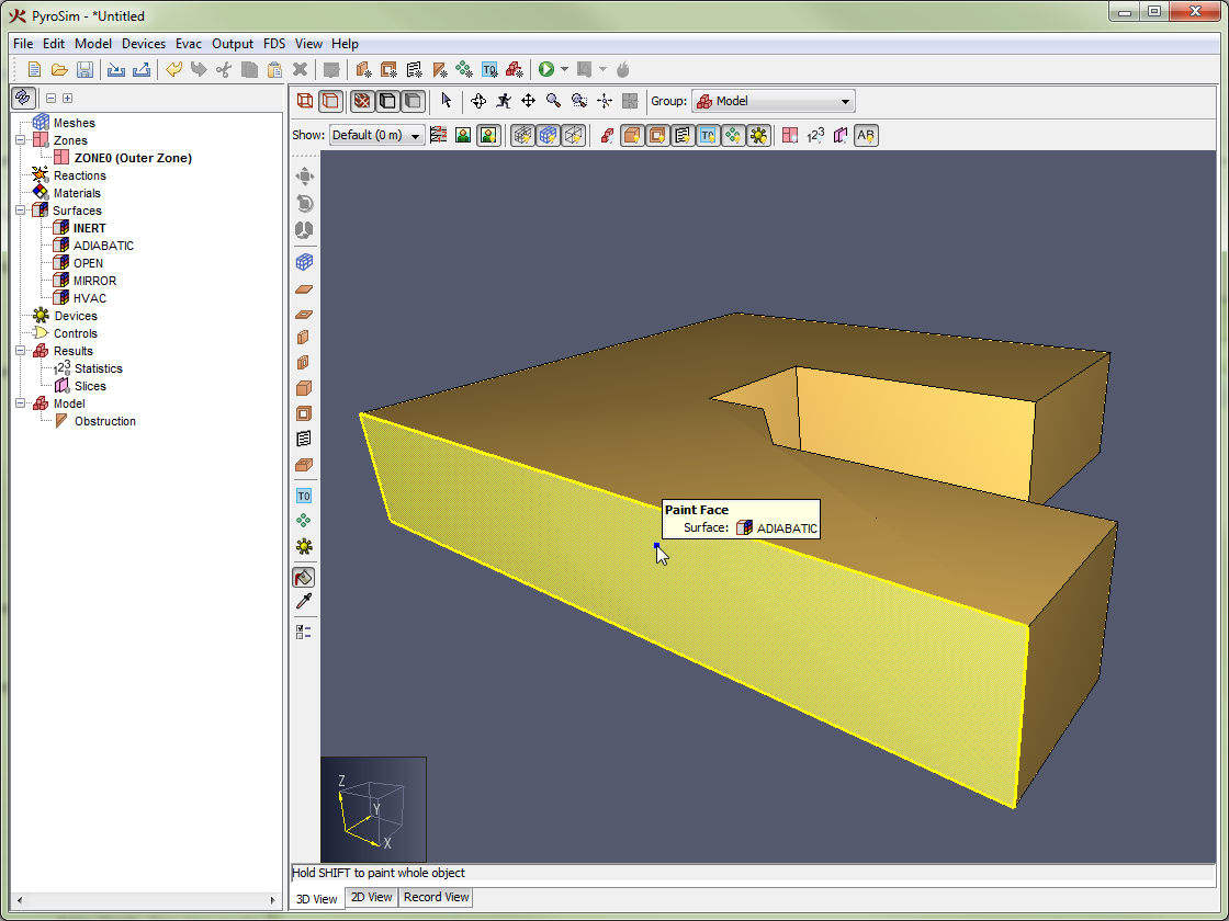
The Pick Tool (![]() ) can be used to pick the next color/surface to use when drawing or painting obstructions and vents.
) can be used to pick the next color/surface to use when drawing or painting obstructions and vents.
The Pick Tool has the following tool properties:
The pick options can also be toggled by pressing CTRL on the keyboard or from the tool’s right-click menu.
To use the Pick Tool, perform the following:
The chosen color/surface will then be applied to the surface or color properties for the obstruction, vent, mesh, and paint tools.
PyroSim provides a Measure Tool (![]() ) to measure distances in the model.
) to measure distances in the model.
To measure a distance, perform the following:
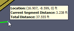
This chapter provides guidance on using the geometry tools available in PyroSim to create several geometric shapes that often appear in building models. The ability to sketch in different planes, copy, replicate, drag, scale, and rotate objects can greatly simplify the tasks of geometry creation.
While PyroSim’s tools do not explicitly produce curved walls, they can approximate them using any of the following techniques:
In all of the following examples, we will use a background image as a pattern to draw against. While this is not required, it makes creating curved surfaces much easier and one of the strengths of PyroSim is that it allows you to sketch geometry directly on top of building design images. The background image we will be using is shown in Figure 103.
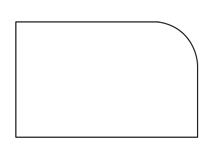
For simplicity, we will assume that horizontal distance across the entire image is 50 feet, and we will place the origin of the model at the lower-left corner of the room shown in the image. The brightness of the image will be set to 50%. The Configure Background Image dialog shown in Figure 104 illustrates these settings.
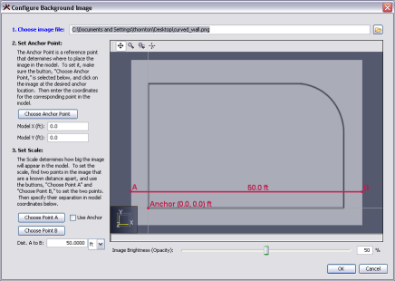
To create a curved wall section from wall segments, you can follow these steps:
This is the fastest way to create smooth curves in PyroSim. PyroSim will convert the curved walls to blocks before running the FDS simulation. While smaller segments will make the wall look better in PyroSim, placement of obstructions generated for FDS depends on the resolution of your mesh. A curved wall drawn with three different segment lengths created with this technique are shown below.
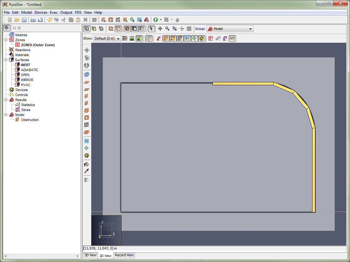 | 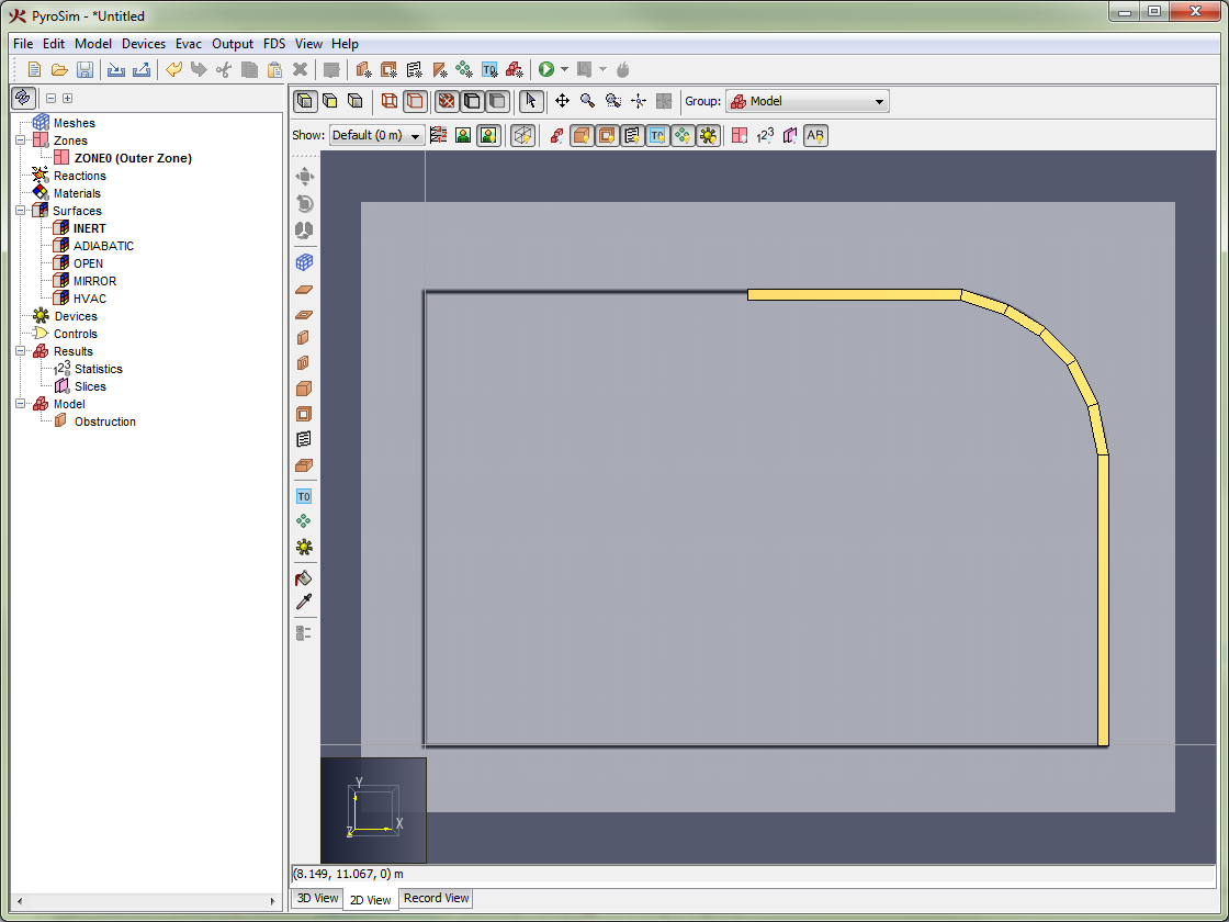 |  |
Using extremely short line segments will probably not be of any benefit unless you also use very small mesh cells.
To create a curved wall section from blocks, you can follow these steps:
This technique forces you to convert the curve to blocks manually, but the advantage is you know exactly what geometry will be generated for FDS. If you have a high resolution mesh, it may be useful to drag the mouse and "paint" the curve rather than clicking individual blocks. The example curved wall is shown in Figure 108.
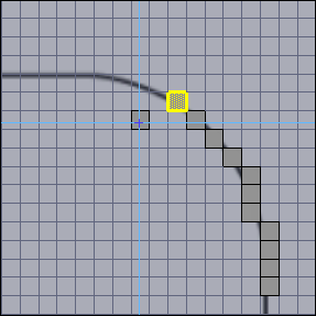
To create curved objects using the rotation technique, you must place an initial segment, then perform a rotate operation about the center point of your desired curve.
This process is illustrated in the following steps:
The curve for this example is shown in Figure 109.
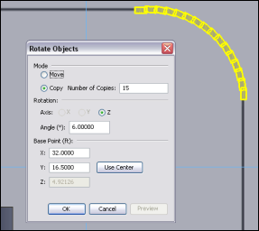
If we would have created 60 copies instead of 15 this procedure would have created a cylinder. While complicated, the rotation approach is the most effective at creating complex symmetrical geometry.
Trusses can be created by drawing a single truss out of slab obstructions and slab holes, then replicating that truss as many times as needed as shown in Figure 110.
The following steps show how to create the trusses for an example roof.
On the toolbar, click the Reset to Front option.
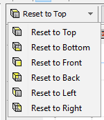
4, set Offset to be 2.0 meters along the Y axis, and click OK.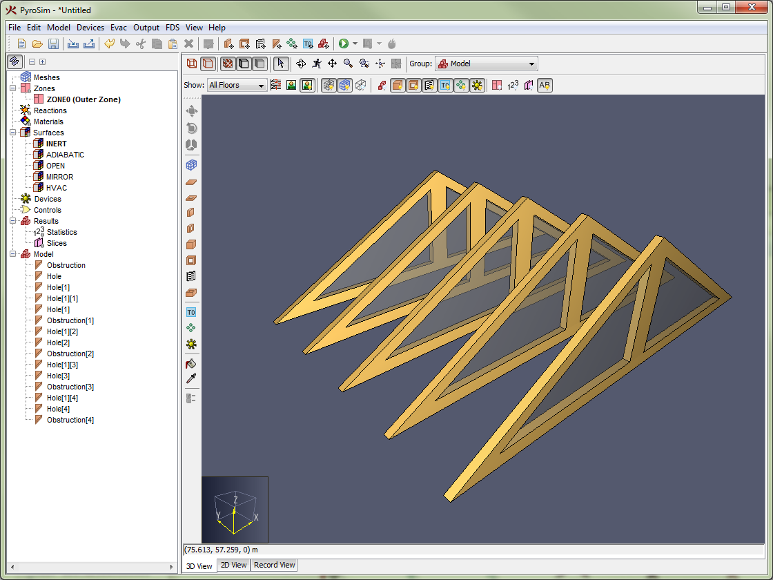
You can quickly add a roof to the model using the Slab Obstruction Tool (![]() ).
).
The following steps show how to add a roof to the previous truss example.
On the view toolbar, Reset to Front.
The resulting roof section is shown in Figure 111.
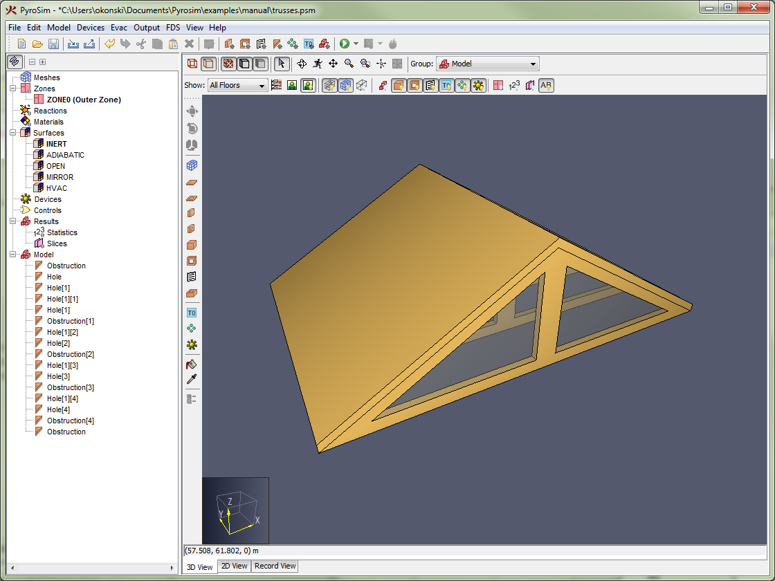
The extruded polygon tool can be used to create obstructions with any number of boundary points (triangles, quads, etc).
Users can create simple stairways by placing the initial stair, then using the move operation. This section will present a simple example to illustrate the approach.
We will create a 10 step stairway. Each step will have a 7 inch rise (0.58 feet), and a 10 inch (0.83 feet) run. The stairway itself will be 24 inches (2.0 feet) wide. To keep things as simple as possible, we will construct the stairway in an empty model.
The stairway generated in this example is shown in Figure 112.
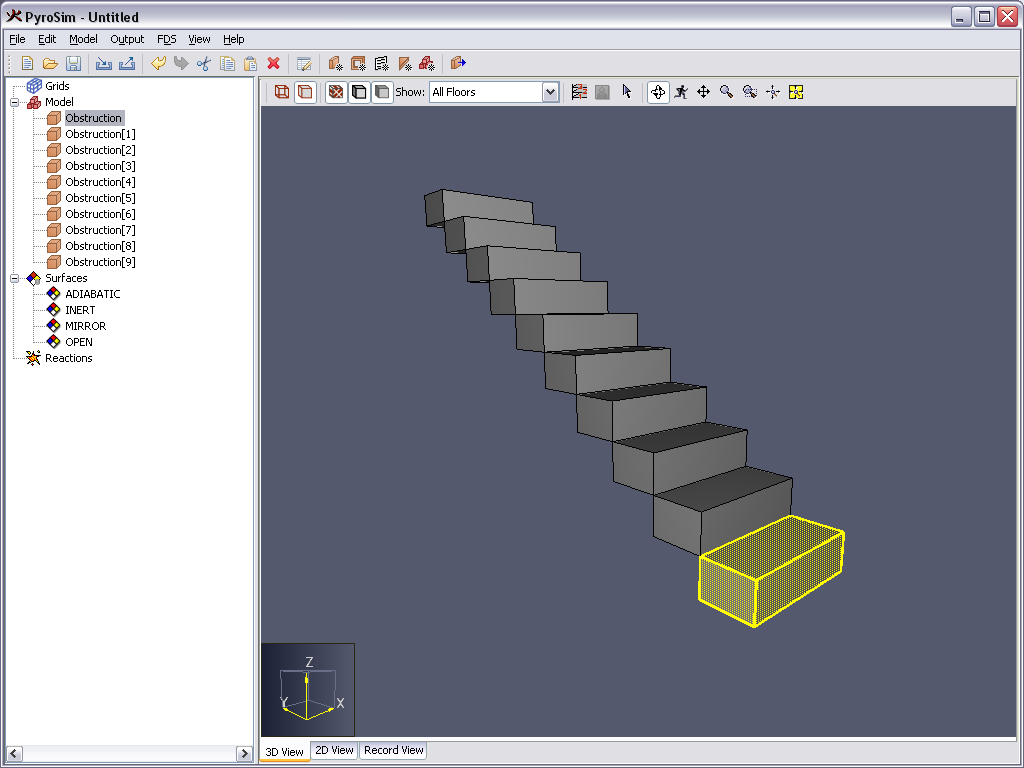
PyroSim relies heavily on the idea of selected objects.
For almost all operations, the user first selects an object(s) and then changes the selected object(s).
The Selection Tool (![]() ) is used to select objects.
) is used to select objects.
Once objects have been selected, the user can modify the object using the menus.
Selection can be made in any of the views using the Selection tool. Multiple objects can be selected using the Ctrl key or click and drag to define a box. In the Navigation View, the Shift key can be used to select a consecutive list of objects.
A right-click on a selection displays a context menu. This menu includes the most common options for working with the object. The user may also right-click on individual objects for immediate display of the context menu.
All geometric changes to the model can be undone and redone using the Undo (![]() ) and Redo (
) and Redo (![]() ) buttons, as well as Ctrl+Z and Ctrl+Y, respectively.
) buttons, as well as Ctrl+Z and Ctrl+Y, respectively.
Select an object to copy, then either use Ctrl+C or Edit→Copy to copy. Alternately, right-click on an object to display the context menu with Copy.
Either use Ctrl+V or Edit→Paste to paste a copy of the object. Alternately, right-click on an object to display the context menu with Paste.
By running two instances of PyroSim, you can copy objects from one model and paste them into a second model. If the copied objects rely on other properties, such as surfaces, that are not included in the second model, these properties will be pasted into the model when the objects are pasted.
Copy/paste can also be performed to and from text files. For example the user can select an object in PyroSim, open a text file, and paste the object. The text FDS representations of the object and dependent properties will be pasted. Alternatively, the user can copy the text from an FDS file and paste into PyroSim (the 3D View, 2D View, or Navigation View). The object will be added to the PyroSim model. An error message will be received if the pasted object depends on data that is not available in the PyroSim model. The user will then need to paste that information (such as surface properties) first before pasting the geometric object.
Double-clicking on an object opens the appropriate dialog for editing the object properties.
The Move dialog can be used to both move an object and to create copies of an object, each offset in space.
To move an object in this manner, perform the following:
The Mode selects either the option to move only the selected object or to create copies of the object and move them. The Offset parameters indicate the increment to move or offset the copies.
To preview the changes without applying them, click Preview. To apply the changes and close the dialog, click OK. To cancel the changes instead, click Cancel.
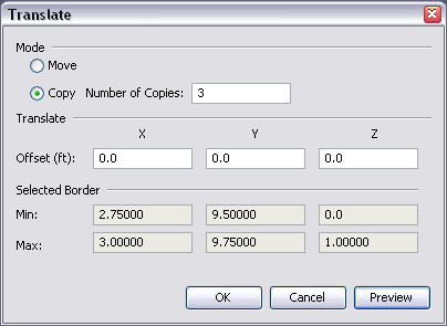
The Mirror dialog can be used to mirror an object about a plane or planes or create a mirrored copy of an object. To mirror an object in this manner, perform the following:
The Mode selects either the option to mirror only the selected object or to create a mirrored copy of the object. The Mirror Plane(s) define planes normal to the X, Y, and Z axes about which the object will be mirrored. The Use Center button can be used to fill the Mirror Plane data with the center coordinates of the selected objects.
To preview the changes without applying them, click Preview. To apply the changes and close the dialog, click OK. To cancel the changes instead, click Cancel.
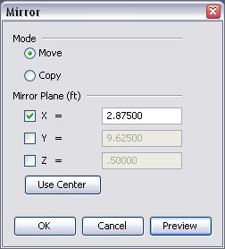
The Scale dialog can be used to change the size of an object or create scaled copies of an object. To scale an object, perform the following:
The Mode selects either the option to scale only the selected object or to create multiple scaled copies of the object. The Scale values define the scale factors in the X, Y, and Z directions. The Base Point defines the point about which the scaling will be performed. The Use Center button can be used to fill the Base Point data with the center coordinates of the selected objects.
To preview the changes without applying them, click Preview. To apply the changes and close the dialog, click OK. To cancel the changes instead, click Cancel.
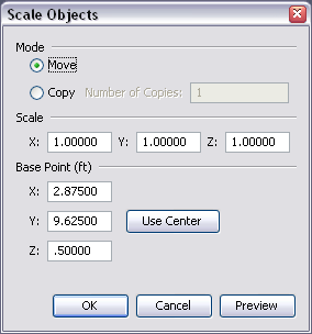
The Rotate dialog can be used to rotate an object or to create rotated copies of an object. To rotate an object, perform the following:
The Mode selects either the option to rotate only the selected object or to create multiple rotated copies of the object. The Rotation values allow the user to select the axis about which the rotation will be made and the angle is the rotation angle (counter-clockwise is positive). The Base Point defines the point about which the rotation will be performed. The Use Center button can be used to fill the Base Point data with the center coordinates of the selected objects.
To preview the changes without applying them, click Preview. To apply the changes and close the dialog, click OK. To cancel the changes instead, click Cancel.
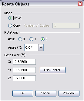
Often it is desirable to turn off the display of selected objects, for example, to hide a roof of a building in order to visualize the interior. In any of the views, right-click on a selection to obtain the following options:
Gas species can serve many different roles in a PyroSim model. In the simplest applications, a number of gaseous species are implicitly defined and tracked within the simulator to model the combustion of hydrocarbon fuels. For this type of model, the Fire Dynamics Simulator simulates and tracks three unique species; AIR, PRODUCTS, and FUEL. These three species can consequently be used anywhere else in the model, and their major components; OXYGEN, CARBON DIOXIDE, WATER VAPOR, NITROGEN, CARBON MONOXIDE, and SOOT can be referenced for output data.
By default, PyroSim adds all species which have been implicitly defined by FDS to the model on startup. These species are unique from those involved in the reaction chemistry, and will not take part in the simple reaction chemistry if referenced. While PyroSim manually handles the logic that determines whether or not it is necessary to include a species in the FDS input file, it is important to understand what requires a species line be written to the output. A species referenced by any of the following will cause it to be written:
Three different classifications of species type can be created in a PyroSim model. The first type are predefined species, whose name’s and chemical properties are known by FDS. The second type are custom primitive species. These differ from predefined species in that they must have their chemical properties defined. And lastly, there are custom lumped species, which are defined as either a mass or volume fraction of predefined and custom primitive species.
Species can be managed by opening the Model menu and selecting Edit Species.
To create either a new species, or include a predefined one, select New and choose whether the species should be Predefined, Primitive, or Lumped.
Primitive species can be tracked individually, or as a component of a more complex lumped species.
To edit primitive species:
Species mixtures can be defined as a mixture of any number of primitive species. Because all species in the simulation must be tracked by a transport equation, a lumped species can be used to save on simulation time.
To create a lumped species:
To edit the lumped species:
When using lumped species, it is recommended that certain actions be taken to reduce the complexity of the simulation.
To save on simulation time:
Doing this check for all primitive species will reduce the number of transport equations solved by the simulator, and save significant time on the simulation.
This chapter provides an overview of how to specify combustion (the reaction of fuel vapor and oxygen) using PyroSim. A more detailed discussion of this topic is provided in the Fire Dynamics Simulator User’s Guide and the Fire Dynamics Simulator Technical Reference Guide.
As described in the Fire Dynamics Simulator User’s Guide, a common source of confusion in FDS is the distinction between gas phase combustion and solid phase pyrolysis. The former refers to the reaction of fuel vapor and oxygen; the latter the generation of fuel vapor at a solid or liquid surface. In an FDS fire simulation, there is only one gaseous fuel that acts as a surrogate for all the potential fuel sources.
In most fire simulations, pyrolysis is defined by specifying a Heat Release Rate Per Unit Area (HRRPUA) as part of a surface. A more complex approach is to define a material with a pyrolysis reaction.
The reaction is defined using the Edit Reactions dialog in PyroSim.
PyroSim supports the "simple chemistry" combustion model in FDS that considers a single fuel species composed of \(C\), \(H\), \(O\), and \(N\) that reacts with oxygen in one mixing-controlled step to form \(H_{2}O\), \(CO_{2}\), \(Soot\), and \(CO\) (see Chapter 12 in the FDS User Guide).
To create a reaction:
The fuel composition is entered on the Fuel tab. If the user selects the Simple Chemistry Model, define the fuel composition by specifying the number of \(C\), \(H\), \(O\), and \(N\) atoms (fractions are acceptable). Alternately, the user can select the fuel from a predefined species list that is given in the FDS User Guide, Table 11.1: Optional gas and liquid species.
To do this:
CRITICAL_FLAME_TEMPERATURE) and the Automatic Ignition Temperature (AUTO_IGNITION_TEMPERATURE).EPUMO2) or specify heat of combustion (HEAT_OF_COMBUSTION).
You can also specify the \(CO\) yield, \(H_{2}\) yield, and \(Soot\) yield.FDS will use the chemical formula of the fuel along with the yields of \(CO\) and \(Soot\), and the volume fraction of hydrogen in the soot to calculate the stoichiometric coefficients for the reaction.
Details of the reaction are output by FDS in the *.out file written during execution.
PyroSim supports the custom smoke features available in FDS. To create custom smoke, first define an species with the desired mass extinction coefficient. This "smoke" species can then be injected into the domain like any other species. Smoke detectors can also detect this smoke species if it is selected under the smoke detector’s model, which can be edited under Edit Smoke Detector Models. on the Devices menu. Finally, if the Results should track this species as smoke, go to the Analysis menu, select Simulation Parameters. and on the Output tab select the mass fraction quantity of the desired species from the Smoke Quantity drop-down box. Note that in addition to specifying the mass fraction of a species, the mass fraction of any mixture fraction species can also be selected for smoke display, including the mass fraction of oxygen, water vapor, and the other species specified in the gas-phase reaction.
PyroSim supports three types of particles: massless tracers, liquid droplets, and solid particles. To create a new particle:
Evaporating liquid droplets can be used with sprinkler spray models and nozzles to customize the spray. They can also be used in particle clouds and surface types that support particle injection.
To specify a liquid droplet, you must specify a species. This can be one of the predefined species recognized in Table 11.1 of the FDS User’s Guide, or any other user defined species. If the species is not predefined, it is important to specify the liquid properties of the species.
To edit the liquid properties of the species:
Liquid species have the following properties.
Properties of the liquid particles are specified in the Particle Dialog.
Drag refers to the drag force the particle exerts on the flow around it, see section "17.4.2 Drag" in the FDS User Guide. There are four Drag options: Sphere (default), Cylinder, Screen and Specify Drag Coefficient.
The Dense Volume Fraction value must be ⇐1.0 and is discussed in section "17.3.5 Dense Clouds of Droplets" in the FDS Users Guide.
Liquid particles can be injected into the domain as evaporating fuel vapor that will burn according to the combustion model specified in the active reaction.
To specify a fuel particle, set the liquid particle’s species to the same species as the Fuel Species for the active reaction, see Reactions.
For instance, if the fuel species of the active reaction is METHANE, choose METHANE for the particle species as well.
If the active reaction is using the Simple Chemistry Model option, choose the species, REAC_FUEL for the particle species.
PyroSim provides basic support for specifying solid particles. A solid particle must reference a surface, from which it derives its thermophysical and geometric parameters. A solid particle can be used to model various heat transfer, drag, and vegetation applications. Most of the parameters unique to solid particles must be defined on the Advanced Panel, see Advanced FDS Parameters.
Massless tracer particles can be used to track air flow within a simulation. They can be used with the particle injection feature of the Burner, Heater/Cooler, Blower, and Layered surface types. They can also be used in particle clouds.
By default, PyroSim provides a black, massless tracer particle called Tracer. To use a custom tracer particle in your simulation, you can modify the parameters of this default particle to suit your needs, or you can create a new particle.
The tracer particle properties are as follows:
-1 uses the FDS default value for this property.
Set to an integer greater than 1 to reduce the size of particle output.Normally, the insertion of particles into the domain is controlled by the surface or object emitting them, such as by a fan or supply surface or a particle cloud. Alternatively, the insertion of particles can be controlled by a device or other control logic. For more information on controls, see Control Logic.
There are two global options relating to particles in the Simulation Parameters dialog. The first option, Droplets Disappear at Floor, can be used to prevent droplets from gathering on the floor of the simulation area. The default value for this option is ON. The second option, Max Particles per Mesh, can be used to set an upper limit on the number of particles allowed in any simulation mesh.
Particle Clouds provide a way to insert particles into the simulation either in a box-shaped region or at a specific point. Particles can either exist at the start of the FDS simulation or can be inserted periodically.
To create a particle cloud, on the Model menu, click either New Particle Cloud. to create a region of particles or New Particle Location. to specify a specific point for the particles. This will show the particle cloud dialog as in Figure 117.
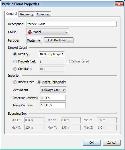
Particle clouds have the following properties:
The geometry properties, including the size and location of the volume or the point location can be specified on the Geometry tab.
Press OK to create the new particle cloud. It will appear as a translucent box or a point in the 3D and 2D Views.
Devices are used to record quantities in the model or to represent more complex sensors, such as smoke detectors, sprinklers, and thermocouples.
You can make time history plots of device output in PyroSim by opening the CHID_devc.csv file.
Devices can be moved, copied, rotated, and scaled using the tools described in Working with Geometry Objects. Most often, the user will simply select one or more devices, right-click to display the context menu, and click Move. By copying a single device along a line and then copying the line in the normal direction, it is possible to quickly define an array of devices.
When a device is defined, a trigger value (setpoint) can be created that can be used to activate other objects. This is discussed more in Control Logic.
In addition, the output of a device can be frozen at its current value when another control activates. This can be used to create more complex logic, such as holding the heat release rate of a fire at its current value when a sprinkler activates.
An aspiration detection system groups together a series of soot measurement devices. An aspiration system consists of a sampling pipe network that draws air from a series of locations to a central point where an obscuration measurement is made. To define such a system in FDS, you must provide the sampling locations, sampling flow rates, the transport time from each sampling location, and if an alarm output is desired, the overall obscuration setpoint.
To define the soot measurement devices:
To define the aspiration detection system:
Supply the following information for the aspiration detection system, Figure 118.
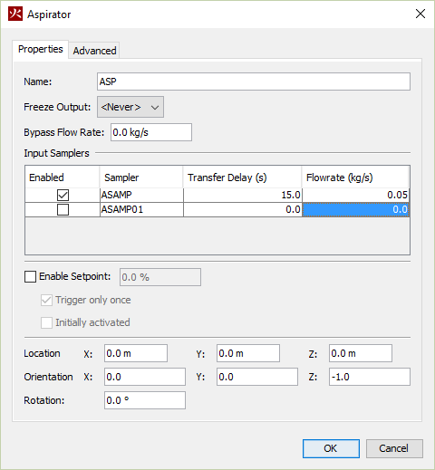
The output of the aspiration detection system will be the combined obscuration.
Simple gas phase and solid phase devices can be used to measure quantities in the gas or solid phase. To define a measurement device, on the Devices menu, click New Gas-phase Device or New Solid-phase Device.
The device properties are:
To create a thermocouple, on the Devices menu, click New Thermocouple.
The thermocouple properties are:
The output of the thermocouple is the temperature of the thermocouple itself, which is usually close to the gas temperature, but not always, since radiation is included in the calculation of thermocouple temperature.
The flow measurement device can be used to measure a flow quantity through an area. To create a flow measuring device, on the Devices menu, click New Flow Measuring Device.
The flow measurement device properties are:
The output will be the total flow through the defined area.
The heat release rate device measures the heat release rate within a volume. To define a heat release rate device, on the Devices menu, click New Heat Release Rate Device.
The heat release rate device properties are:
The output will be the total heat release rate within the volume.
There is often the need to estimate the location of the interface between the hot, smoke-laden upper layer and the cooler lower layer in a burning compartment. Relatively simple fire models, often referred to as two-zone models, compute this quantity directly, along with the average temperature of the upper and lower layers. In a computational fluid dynamics (CFD) model like FDS, there are not two distinct zones, but rather a continuous profile of temperature. FDS uses an algorithm based on integration along a line to estimate the layer height and the average upper and lower layer temperatures. To define a layer zoning device, on the Devices menu, click New Layer Zoning Device.
The layer zoning device properties are:
The output will be the quantities selected.
A beam detector measures the total obscuration between points. To define a beam detector device, on the Devices menu, click New Path Obscuration Device.
The path obscuration device properties are:
The output will be the percent obscuration along the path.
A heat detector measures the temperature at a location using a Response Time Index model. To define a heat detector device, on the Devices menu, click New Heat Detector.
The heat detector device properties are:
The output will be the heat detector temperature.
A smoke detector measures obscuration at a point with two characteristic fill-in or "lag" times. To define a smoke detector, on the Devices menu, click New Smoke Detector.
The smoke detector device properties are:
The output will be the percent obscuration per meter.
Sprinklers can spray water or fuel into the model. To define a sprinkler:
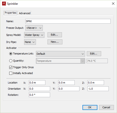
The sprinkler properties are:
Nozzles are very much like sprinklers, only they do not activate based on the standard RTI model. They can be set to activate by custom control logic.
Objects can be set to activate or deactivate during the simulation using activation events. Activation events are the control logic system in FDS and can be set on each geometric simulation object (e.g. walls, holes, vents) using the Activation option in the object’s Properties dialog. PyroSim supports activation events based on time and input devices. Some uses of activation events include:
To open the dialog shown in Figure 120: On the Devices menu, click Edit Activation Controls.
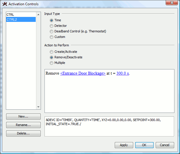
Creating controls in PyroSim takes 3 steps:
After selecting an input type and an action, a pattern (in sentence form) for describing the control logic will appear in the dialog. Some key words and numbers will be drawn in blue and underlined. Any blue text can be clicked to modify the behavior of the specific control.
Figure 121 shows the selector popup for objects. Objects are selected by name. To quickly find objects in the selector popup, you can type the first few letters of the object’s name.
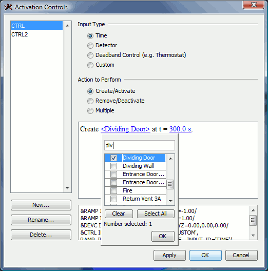
Activation controls are stored separately from specific geometric objects. This makes it possible to bind an object to a control after it has been created. You can use the Activation box in an object’s properties editor to bind that object to an existing activation control, or even create a new control directly. Figure 122 shows the activation control in the object properties dialog for a hole.
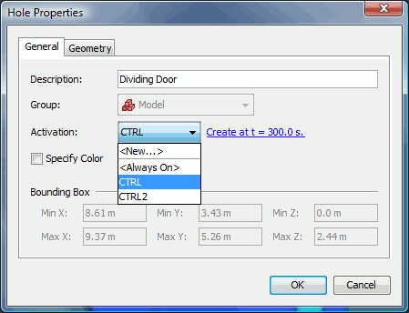
Once a control has been bound to an object (or objects) any objects linked to that control will show a text description of the control in their properties editor. This text will be shown in blue and underlined and can be clicked to edit the activation control. Changes made to the activation control will impact all referencing objects.
To create or remove an object at a specific time, select Time for the Input Type in the Activation Controls dialog. When using time as the input, objects can be created at a specific time, removed at a specific time, or be created and removed periodically throughout the simulation. To create or remove the objects once, select Create/Activate or Remove/Deactivate under the Action to Perform. To create/remove the object periodically, select Multiple under the Action to Perform. When performing multiple timed events, the creation and removal and times at which they occur are specified in the table at the bottom of the dialog. The create and remove events should alternate as time increases.
To create or remove some objects based on a device in the model, the device must first have a setpoint enabled.
To specify a setpoint, perform the following:
Once the desired devices have been given a setpoint, they can be used as inputs to the control logic expression. Now in the Activation Controls dialog, select Detector as the Input Type. The detector can be used to Create/Activate or Remove/Deactivate the desired objects when the detector either activates or deactivates. If more than one detector is to be used to activate the objects, the descriptive sentence can be used to decide if the objects should trigger when any, all, or a certain number of the devices activate.
In PyroSim, HVAC (Heating, Ventilation, and Air Conditioning) systems are specified as networks of ducts, nodes, and some combination of fans, aircoils, and filters.
A duct is required for any HVAC system. At a basic level, a duct represents the joining of two HVAC Nodes.
To define an HVAC Duct:
You can now edit the duct:
An HVAC Node represents a either a joining of two or more HVAC Ducts, or the meeting point between a duct and the PyroSim computational model. To create an HVAC Node:
You can now edit the node.
An HVAC Fan is used to generate airflow in a HVAC network. A fan is specified between two nodes by selecting it as the Flow Device for an HVAC Duct. Note that an HVAC Fan is a class of object, and a single fan definition can be used by any number of ducts.
To create an HVAC Fan:
An HVAC Filter is used to stop gaseous species from circulating in the HVAC system. A given filter can limit the flow of any number of valid species defined in the model. Note that an HVAC Filter is a class of object, and a single filter definition can be referenced by any number of nodes.
To create an HVAC Filter:
An HVAC Aircoil is a device that provides a heating or cooling element to an HVAC system. An aircoil is specified between two nodes by selecting it as the Flow Device for an HVAC Duct. Note that an HVAC Aircoil is a class of object, and a single aircoil definition can be used by any number of ducts.
To create an HVAC Aircoil:
HVAC Vents are used to represent the junction between the HVAC system and the rest of the computational model. See Vents for more information on using vents.
To define an HVAC Vent:
In this chapter we describe the simulation output options available in PyroSim. Each of these options is located in the Output menu.
Solid profiles measure quantities (e.g. temperature, density) as they extend into solid objects. The output file for this measurement device will be named CHID_prof_n where CHID is the job ID and n is the index of the solid profile. This output file contains the data necessary to create an animated 2D chart of the quantity as it extends into the object over time. PyroSim does not currently support displaying this output file.
To generate solid profile output, on the Output menu, click Solid Profiles.
Each solid profile requires the following parameters:
2D Slices or slice planes measure gas-phase data (e.g. pressure, velocity, temperature) on an axis-aligned plane. This data can then be animated and displayed using the 3D Results (Figure 123).
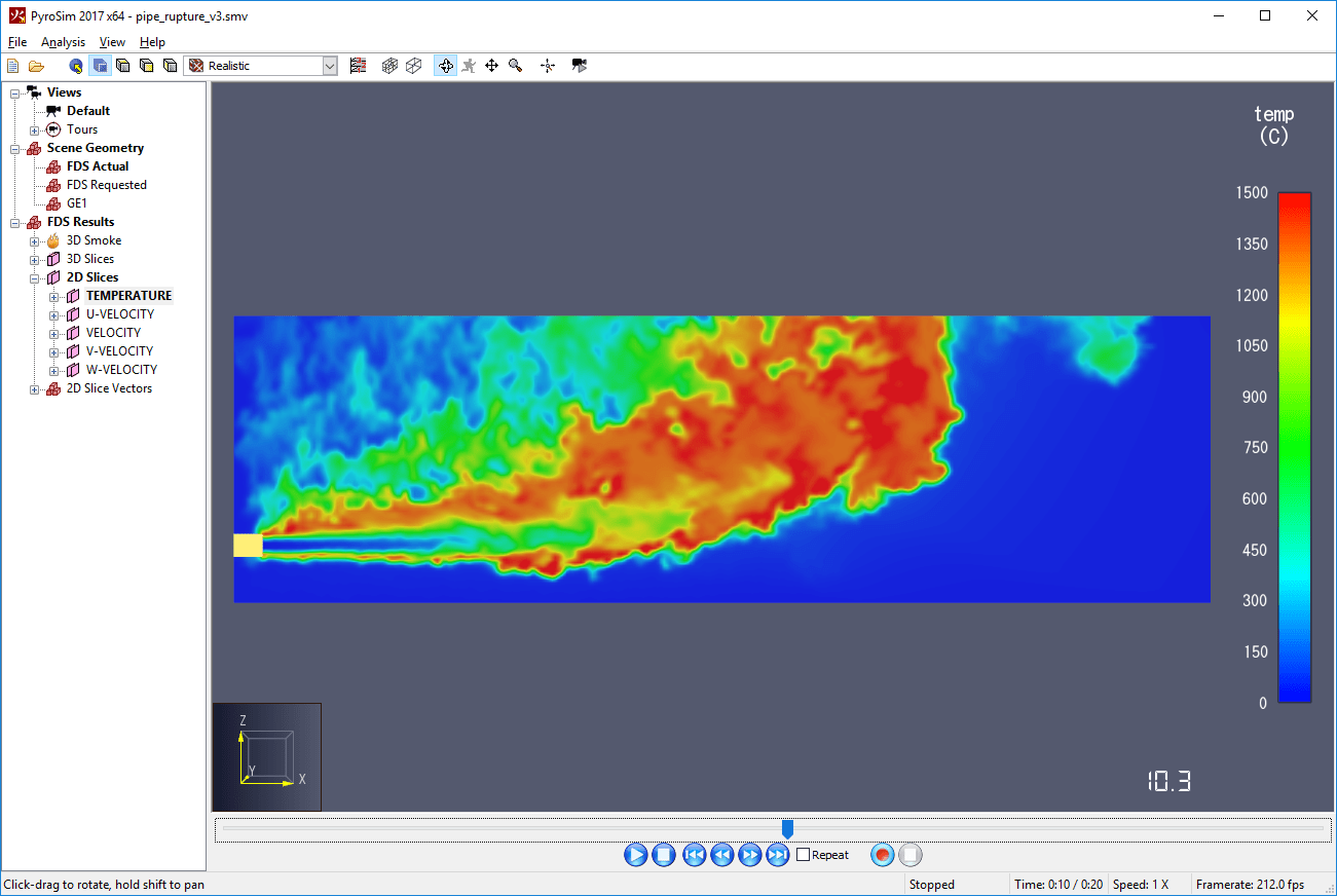
To generate animated slice planes, either draw them using the drawing tools as described in Planar Slice Tool or on the Output menu, click 2D Slices.
Each slice plane requires the following parameters:
3D Slices represent volumetric regions that measure gas-phase data (e.g. pressure, velocity, temperature). This data can then be animated and displayed using the 3D Results in several different ways, including volumetric renderings, plotting 2D slices through the data, plotting points, or creating isosurfaces, all in the 3D Results application. Figure 124 shows a volumetric rendering.
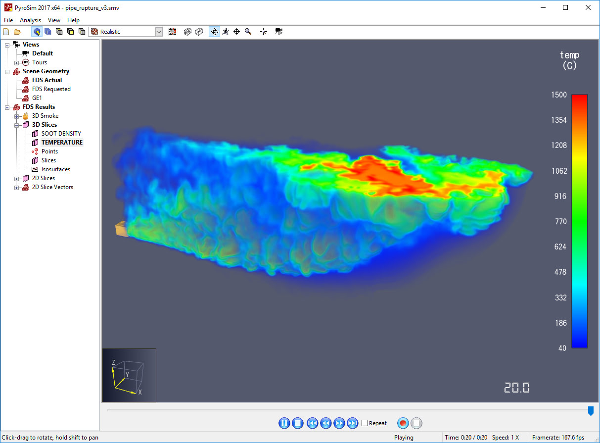
To generate animated 3D slices, either draw them using the drawing tools as described in Other Drawing Tools or on the Output menu, click 3D Slices.
Each 3D slice requires the following parameters:
Boundary quantities provide a way to visualize output quantities (e.g. temperature) on the walls of every obstruction in the simulation. This data can be animated and visualized in the 3D Results (Figure 125). Since the data applies to all surfaces in the simulation, no geometric data needs to be specified.
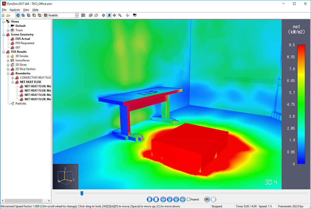
To generate boundary quantity data, on the Output menu, click Boundary Quantities. In the Animated Boundary Quantities dialog, you can select each quantity you would like to be available for visualization.
Isosurfaces are used to plot the three dimensional contour of gas phase quantities. This data can be animated and visualized in the 3D Results (Figure 126).
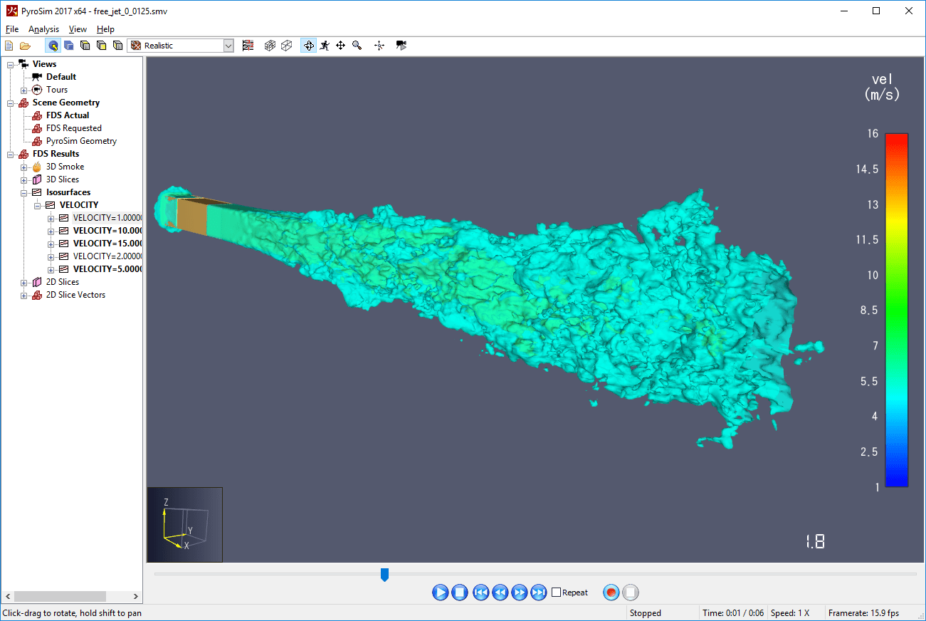
To generate isosurface data, on the Output menu, click Isosurfaces, In the Animated Isosurfaces dialog, you can select each quantity you would like to be available for visualization. Then you must enter values at which to display that quantity in the Contour Values column. If you enter more than one contour value, each value must be separated by the semi-colon character (;). Once you have finished typing the value, press enter.
Plot3D is a standard file format and, like 3D slices, can be used to display 2D contours, vector plots, and isosurfaces in a volumetric region the 3D Results (Figure 128). PLOT3D output is formed of two parts: an XYZ file containing information about the structure of the mesh, and a Q file for each output time. Each Q file contains data for up to five quantities. Simulations with multiple meshes have XYZ and Q files for each mesh. The 3D Results will automatically stitch the individual Q files together to animate the results.
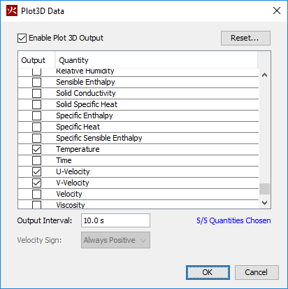
PLOT3D data can also be used by the Pathfinder evacuation simulation software to integrate with FDS results. To quickly select the quantities useful in Pathfinder, including the FED calculation, click the Reset button and click Pathfinder Quantities.
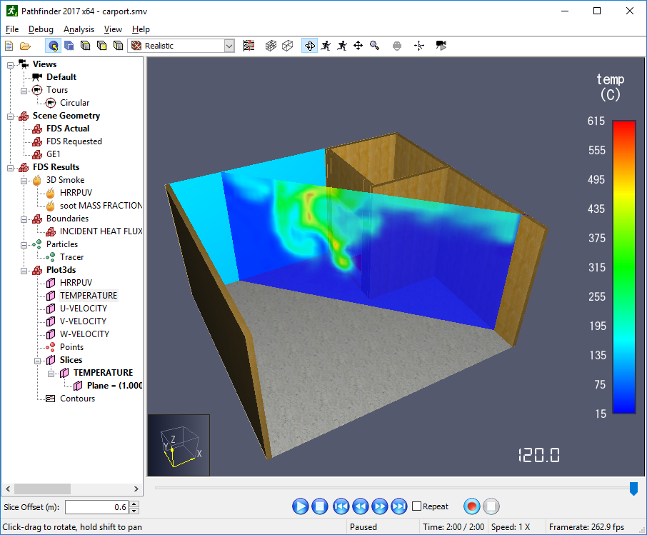
Enabling PLOT3D data in PyroSim will cause the XYZ file to be written. In previous versions of PyroSim, it was possible to generate PLOT3D output without writing the XYZ file. While this offered a way to save space in the simulation output, this sometimes led to errors when loading PLOT3D output without an XYZ file. Loading an old PyroSim file that includes PLOT3D output but is set not to write the XYZ file will cause the XYZ file settings to be ignored and the file will be written anyway.
Statistics output is an extension of the devices system. You can insert a statistics gathering device and it will output data about the minimum, maximum, and average value of a particular quantity in one or more mesh. This data can then be viewed in a 2D chart using PyroSim (Figure 129).
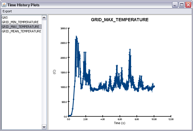
To generate statistics data for some region, on the Output menu, click Statistics. then click New. Once a quantity is selected, some combination of the following options is available depending on whether the quantity is gas or solid-phase and what units are output by the quantity:
The output file for measurement devices will be named CHID_devc.csv where CHID is the job ID.
All aspects of running an FDS simulation can be performed through the PyroSim user interface. This includes setting up simulation parameters, executing single- and multi-threaded simulations, running a remote cluster simulation, and resuming previously stopped simulations.
Before running a simulation, FDS simulation parameters should be adjusted to fit the problem. This can include parameters such as simulation time, output quantities, environmental parameters, conversion of angled geometry to blocks, and miscellaneous simulator values.
To edit the simulation parameters, on the Analysis menu, select Simulation Parameters.
This shows the simulation parameters dialog. The parameters are split into several categories, with each category on another tab of the dialog.
All time-related values can be entered on the Time tab as shown in Figure 130.
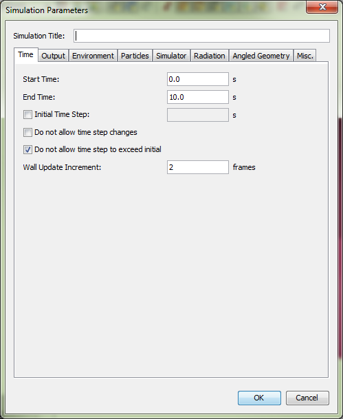
The Output tab provides fine-grained control of how output values are recorded.
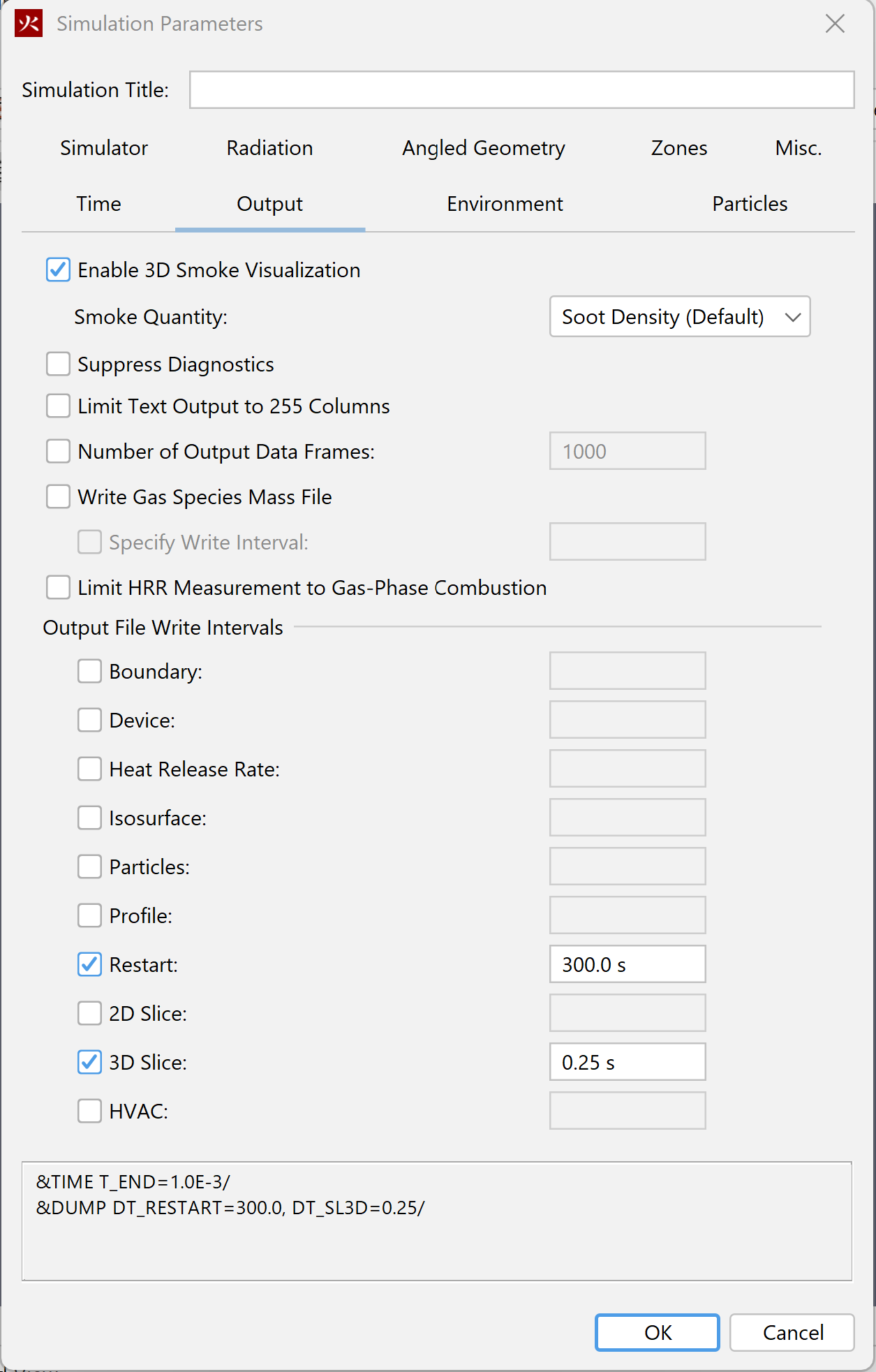
The Environment tab enables various ambient environmental properties to be set as shown in Figure 132
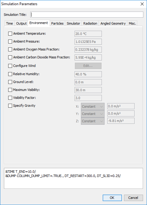
A unique aspect of this tab is the specification feature for gravity. Gravity, in each of the X, Y, and Z directions, can be defined as a ramped function. This allows users to model complex behavior of gravity in tunnel or space applications where spatial or temporal variations in direction may change the magnitude vector. Each ramp can be set to vary as a function of either the position along the X direction, or time.
While the Environment tab provides control over ambient environmental conditions, different temperatures, pressures, and mass fractions of species can be specified in various sub-regions of the model by using Init Regions.
To create an Init Region, exit the Simulation Parameters dialog, and on the Model menu, choose New Init Region.
This opens the Initial Region dialog as shown in Figure 133. Specify the desired temperature, pressure, or mass fraction of species to override in the region on the General tab and enter the volume parameters on the Geometry tab. Press OK to create the Init Region.
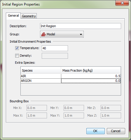
Wind parameters can be specified by checking Configure Wind and then clicking the Edit button. This will open the Wind dialog as shown in Figure 134.
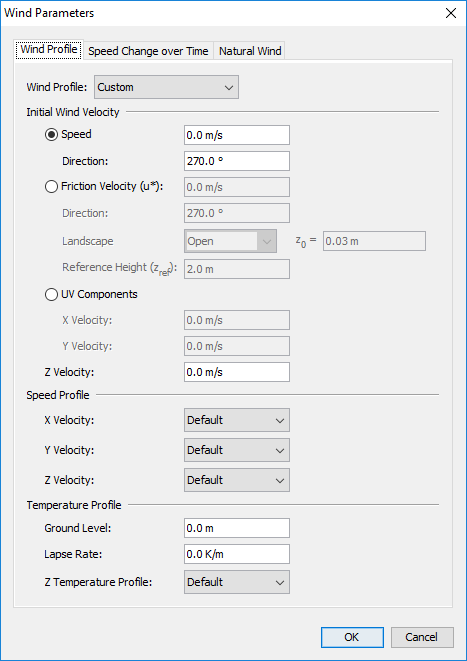
The Wind Profile tab provides control over how the wind speed and temperature develops as a function of the elevation. There are two options available for defining the Wind Profile, Custom and Monin-Obukhov Similarity.
The Custom Profile parameters provide fine-grained control over the initial wind speed, direction, and velocity and temperature as a function of elevation.
If the Wind Profile is set to Monin-Obukhov Similarity as shown in Figure 135, the wind profile is specified using a set of similarity parameters as defined in the FDS User’s Guide.
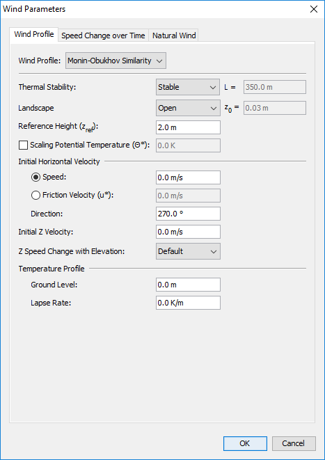
The Speed Change over Time tab allows control over the wind velocity as a function of time. While the wind profile determines the base speed at various locations and elevations in the model, the speed change over time parameters provide multipliers that are applied to these values to vary them over time.
The Natural Wind tab provides the ability to allow wind to develop naturally by specifying pressure drops over distance. This may be useful for modeling transit tunnels.
The Simulator tab provides control over the simulator used in FDS. Refer to the FDS User Manual for more information on various parameters.
The Radiation tab provides control over radiation parameters used in FDS. Refer to the FDS User Manual for more information on radiation parameters.
PyroSim allows obstructions and holes to be drawn that are not aligned with the solution mesh needed by FDS (Figure 139). To write the FDS input file, PyroSim must convert these objects to axis-aligned blocks, first. PyroSim will either do this automatically when the FDS input file is generated, or this can be done manually for individual objects by right-clicking the object and selecting Convert to Blocks.
The Angled Geometry tab of the simulation parameters dialog provides default parameters that control conversion of obstructions and holes into blocks for the FDS input file as shown in Figure 136.
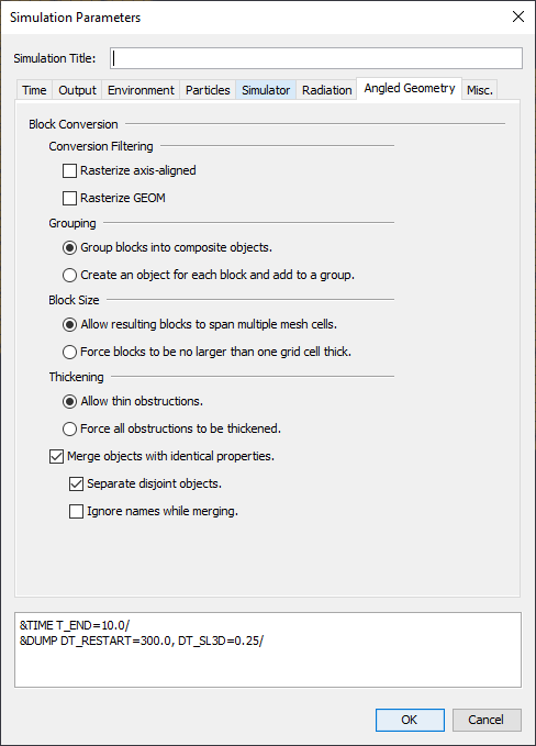
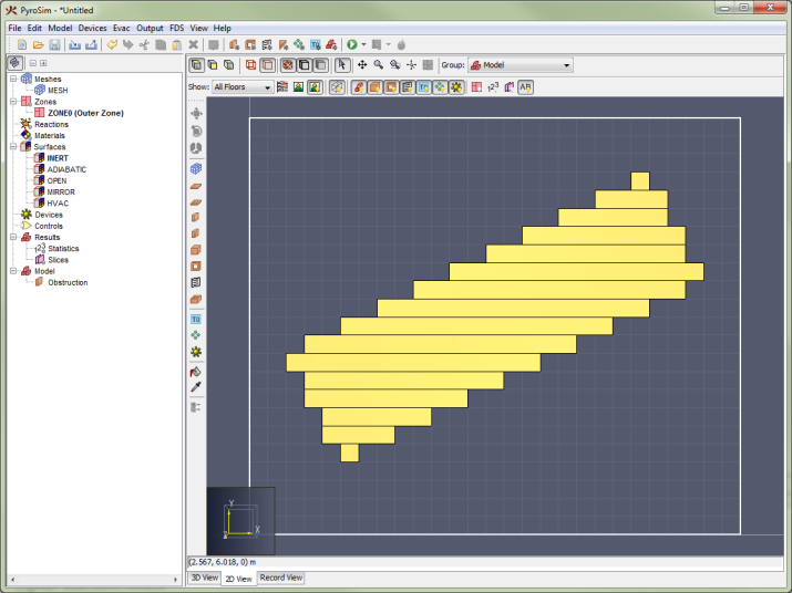 | 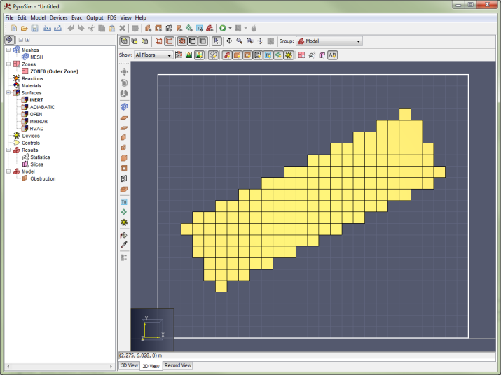 |
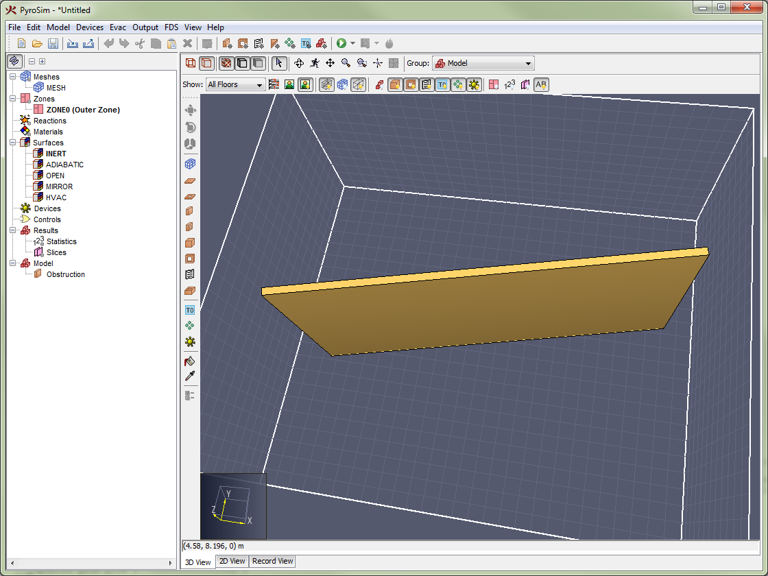 | 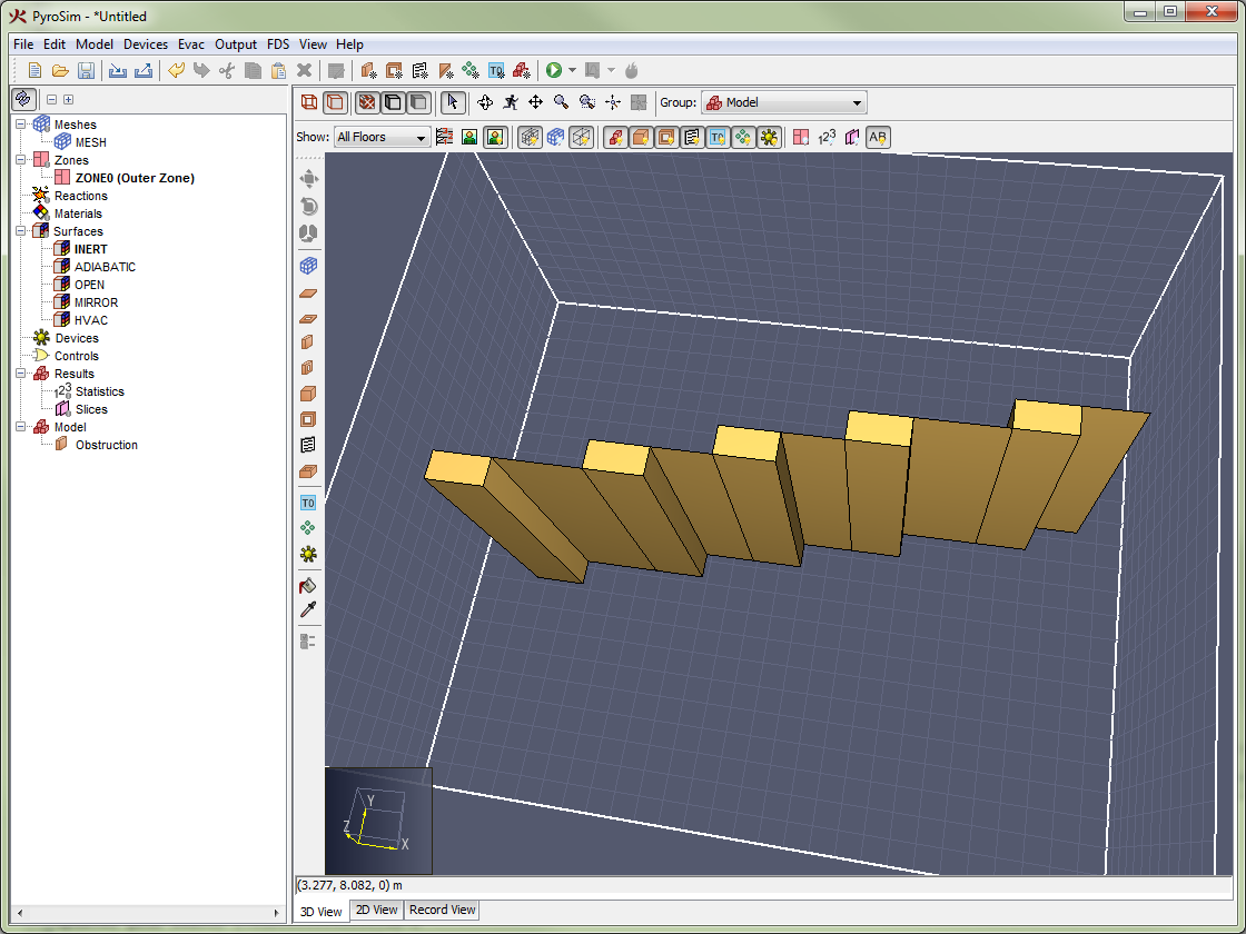 | 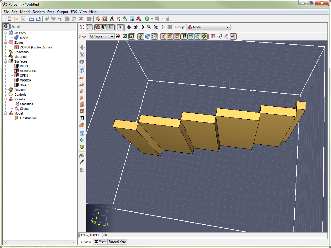 |
This tab allows some miscellaneous simulation and model properties to be set.
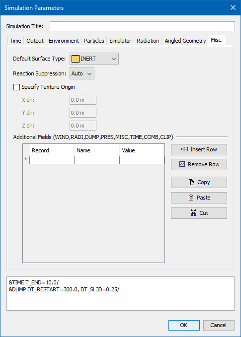
As of FDS version 6.1, FDS added multithreading support using a library called OpenMP. OpenMP will automatically be used to utilize multiple processing cores, if available, during the simulation procedure. The behavior of OpenMP during an FDS simulation is not controlled by the FDS input file, but rather by environment variables.
The OpenMP environment dialog provides a way to edit the environment variables that control OpenMP (Figure 143). These settings are applied to the execution context created by PyroSim and do not alter system environment variables.
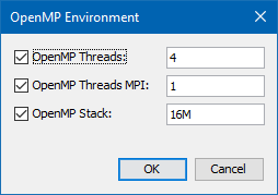
When left unset, OpenMP calculates a value (for example, 32-bit OpenMP uses 256M). Because the OpenMP’s calculated value tends to cause FDS to crash with a segmentation fault, PyroSim sets this value to 16M by default. An upper bound suggested by NIST is 200M.
Once you have created a fire model, you can run the simulation from within PyroSim.
FDS actions can be accessed from either the Analysis menu or the main toolbar, as shown in Figure 144.
To begin a simulation: on the Analysis menu, click Run FDS.
or click ![]() from the main toolbar.
Simulations launched in this way can use multiple OpenMP threads, but will not use multiple MPI processes.
from the main toolbar.
Simulations launched in this way can use multiple OpenMP threads, but will not use multiple MPI processes.

PyroSim will create a sub-directory of the current PyroSim file to store FDS input and results.
So for instance, if the PyroSim file is named C:\pyrosim_files\switchgear.psm, the results will be stored in C:\pyrosim_files\switchgear.
PyroSim will save a copy of the current PyroSim file into this directory and create the following files:
.fds).views) [optional].floors).pyrogeom) [optional].ini) [optional].ge1) [optional]The file preferences control whether the optional files are written, see Preferences for more information.
The input files will automatically be named after the PyroSim file.
With the default preferences, for the "switchgear" example, the files would be switchgear.fds, switchgear.views, switchgear.pyrofloors, and switchgear.pyrogeom.
All result files from FDS will also be stored in this directory.
Next, the FDS Simulation dialog shown in Figure 145 is launched. This dialog, which shows FDS progress and messages, can be minimized and you can continue using PyroSim (and even run additional simulations) while a simulation is running.
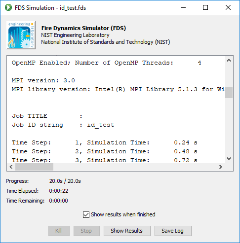
.stop file that signals FDS to stop the simulation, but also write out a checkpoint file that can be used to resume the simulation later.
There is often a significant delay between the time when you click the Stop button and when the simulation actually terminates.
This is because FDS checks for the stop file at the same rate that it updates the progress information.PyroSim includes support for FDS’s MPI-based multi-process execution. When running a simulation with multiple MPI processes, all of the computation within each of the meshes can take place independently. Assuming a simulation executes in t seconds using only one processor, the best possible performance improvement using n processors and n meshes is a reduction to t/n seconds.
To launch a simulation that uses multiple MPI processes:
or
Before running a parallel simulation, you may want to take into account some guidelines:
For a detailed list of suggestions and information about running FDS in parallel, please consult section 6.3.2 of the FDS Users Guide.
PyroSim supports the ability to run an FDS simulation on a network cluster using MPI. This has similar restrictions to running a parallel simulation, in that each grid is run in a separate process. The cluster may be composed of several computers, or nodes, and each node may have any number of processors.
Cluster simulations have the following configuration requirements:
pmi_proxy.exe.
It is not necessary to license PyroSim on machines that will be used only as simulation cluster nodes.To launch a cluster simulation within PyroSim:
or
This will launch the Cluster FDS Parameters dialog as shown in Figure 146.
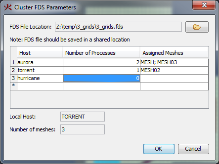
All nodes in the cluster can be entered in the table, along with the number of processes to launch on each node.
Click the OK button to begin the simulation.
All input and output files will be stored in the same directory as the specified FDS file. In addition to the standard input files, PyroSim will also copy the appropriate FDS and MPI executables into the FDS file’s directory. This ensures that all nodes in the cluster use the same versions of FDS and MPI.
PyroSim supports the ability to run an FDS simulation in the cloud. PyroSim currently integrates with CFD FEA Service’s Cloud HPC. Users can view pricing details and register for Cloud HPC on their website.
To launch a cloud simulation within PyroSim:
This will launch the Cloud FDS Parameters dialog as shown in Figure 147.
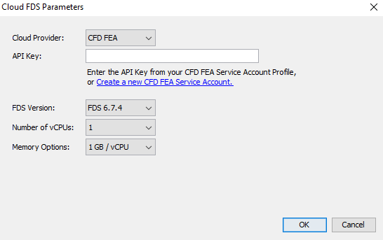
The Cloud FDS Simulation dialog, as seen in Figure 148 has a few distinct differences from the normal FDS Simulation dialog.
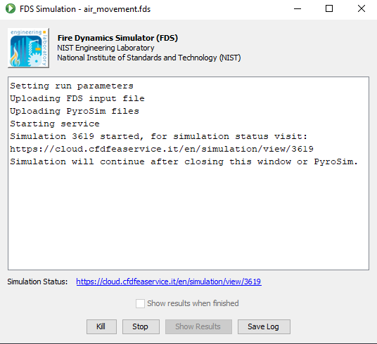
After a simulation is launched in the cloud, the Cloud FDS Simulation dialog will not keep track of its status. It instead cedes to the dashboard of the Cloud Provider once the simulation has successfully been started. The simulation will continue to run, even after you close the Cloud FDS Simulation dialog. You may access the dashboard page for your simulation from the link provided in the Status field on the dialog.
The behavior of the Kill and Stop buttons may change depending on your Cloud Provider. For CFD FEA, the Kill button will wipe the simulation and not produce any results, while the Stop button will save the simulation and its results at its current step.
Users may also find links to the dashboards for the available Cloud Providers from within PyroSim:
If an FDS simulation has been gracefully stopped by pressing the Stop button in the simulation dialog, it can later be resumed. To do so, on the Analysis menu, click Resume Simulation. This will cause an additional RESTART flag to be written to the FDS input file. When FDS detects this flag it will automatically attempt to reload the previous execution state from the hard disk and resume where it left off. If FDS is unable to load the previous execution state, it will exit with an error.
When PyroSim creates an FDS input file, it also outputs a PyroSim Geometry (.pyrogeom) file if enabled in the preferences, see Results Preferences. This file contains information about the scene geometry, including obstructions, vents, meshes, and other CAD data before they are converted to blocks. This allows the Results to show a detailed, animated view of the model along with FDS results.
Each object in this file is linked with the corresponding FDS blocks in the input file. This allows the Results application to show and hide the detailed objects that are activated/deactivated over time due to control logic in the FDS input file (see Control Logic). In order to make this work correctly, however, PyroSim must perform some additional processing on the geometry, including the following:
If there are any OBST, VENT, or HOLE records in the Additional Records section of the Record View, the following message will appear in PyroSim when writing an FDS file:
The additional records section contains OBST, VENT, and/or HOLE records. These objects will not appear in the PyroSim Geometry file and will prevent the geometry file from containing activation logic.
This message indicates that the PyroGeom file will no longer accurately represent FDS objects as they are activated and deactivated. Instead, the PyroGeom objects will always be visible, and all obstructions have all holes subtracted from them in this view (but not in the FDS input file). Objects will no longer show and hide as they would before. Because of this, the FDS snapped obstructions are shown by default in the Results instead of the PyroGeom file.
In order to fix this issue, the OBST, VENT, and HOLE records must be moved from the Additional Records section into the PyroSim model. This can be accomplished by cutting the text of these records and pasting them into the 2D or 3D model view.
PyroSim supports post-processing in three ways:
Results is a powerful post-processor for FDS created by Thunderhead Engineering. It allows the user to view the FDS model along with results in 3D. For Pathfinder users, it also allows the user to combine evacuation results in the same window. For more information, see the Results User’s Manual located in your PyroSim install folder or under the Help menu.
By default, if you run FDS from within PyroSim, the Results Viewer will automatically be launched at the end of the FDS run.
This can be configured in the FDS Simulation dialog by checking "Show results when finished", or by going to the FDS tab in the Preferences dialog and selecting "Run Results when FDS simulation completes".
Alternately, you can click (![]() ) on the Analysis toolbar to launch the most recent results.
You may also run the Results at any time by going to the Analysis menu and selecting Run Results.
This will prompt you to choose a Results file (.smv) to open.
) on the Analysis toolbar to launch the most recent results.
You may also run the Results at any time by going to the Analysis menu and selecting Run Results.
This will prompt you to choose a Results file (.smv) to open.
Smokeview is a post-processor for FDS supplied by NIST. It allows the user to view the FDS model along with results in 3D. The user can view animated smoke, slices, Plot3D, and various other output quantities.
If you run FDS from within PyroSim, Smokeview will not be automatically launched at the end of the FDS run. You may run Smokeview at any time by going to the Analysis menu and selecting Run Smokeview. This will prompt you to choose a Smokeview file to open.
Time history results are saved for heat detectors, thermocouples, and other fire output.
After running an FDS simulation, the most recent plots can be viewed by clicking ![]() on the FDS toolbar.
This will show a plot of thermal results.
Device and control results may also be viewed by by clicking the down-arrow and selecting the desired plot.
on the FDS toolbar.
This will show a plot of thermal results.
Device and control results may also be viewed by by clicking the down-arrow and selecting the desired plot.
Not all results are supported for viewing in PyroSim. FDS output files that are known to not display correctly in PyroSim include CHID_pressit.csv and CHID_cpu.csv. The files CHID_devc.csv, CHID_hrr.csv, and CHID_ctrl.csv are expected to work in most configurations.
Additional plots may be shown by going to the Analysis menu and choosing Plot Time History Results. A typical heat detector plot is shown in Figure 149. The user can export the image to a file.
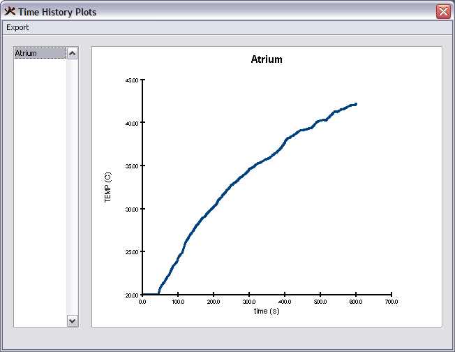
After running a simulation, the results may be archived along with the FDS and PyroSim input files. To do so, on the Analysis menu, click Archive FDS Results. This will show the Archive FDS Results dialog as shown in Figure 150.
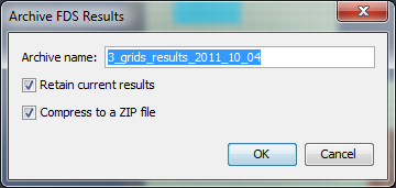
Press OK to create the archive. The archive will be stored in the directory of the current PyroSim file.
Once results have been archived, they can be later restored. To do so, on the Analysis menu, click Restore FDS Results. This will show the Restore Archived Results dialog as shown in Figure 151.
Libraries of material, or other model data, can reduce errors and speed the creation of new models. The user can import data from the library into a new model. This section describes how to manage PyroSim libraries.
You can create and manage your own libraries for data that you commonly use. A library is a single file that can contain several categories of objects, such as Materials, Gas-phase Reactions, and Surfaces.
To manage your library:
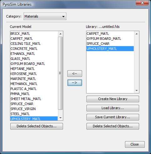
After you have saved your library, you can load it into a new model and copy data from the library to your model.
PyroSim includes a library of reaction and material data that has been gathered from the verification analyses provided with FDS. Each of these reactions and materials has a reference in the Description that documents the source of the data. This library is presently quite limited, and should be used as a starting point and not some kind of "standard" library.
It is your responsibility to verify that this data is correct and applicable to your simulation.
To import data from the PyroSim database:
property_library.fds file that is found in the C:\Program Files\PyroSim 2021 folder.First, a caution. Version 4 of FDS provided a database that included several common materials and reactions. In version 5, the FDS developers made a conscious choice to remove material and reaction data. Many of the materials in FDS 4 were simply examples, and they were worried that users were applying them without using their own test or lab data as validation. In this section, we describe how to import the FDS 4 database, however, it is your responsibility to verify that this data is correct and applicable to your simulation.
You can convert the old FDS 4 materials and reactions for use in PyroSim 2007.
To import FDS 4 data:
Program Files/PyroSim 2007/fds folder and open the database4.data file.PyroSim tries to support FDS completely, but there are some more obscure features that might not be found in the PyroSim user interface. For these items, PyroSim provides additional mechanisms to allow these features through the Additional Records section of the Record View and the Advanced tab of some dialogs.
There are times when PyroSim does not support an entire record. In this case, the record can be entered into the Additional Records Section of the Record View as shown in Figure 153.
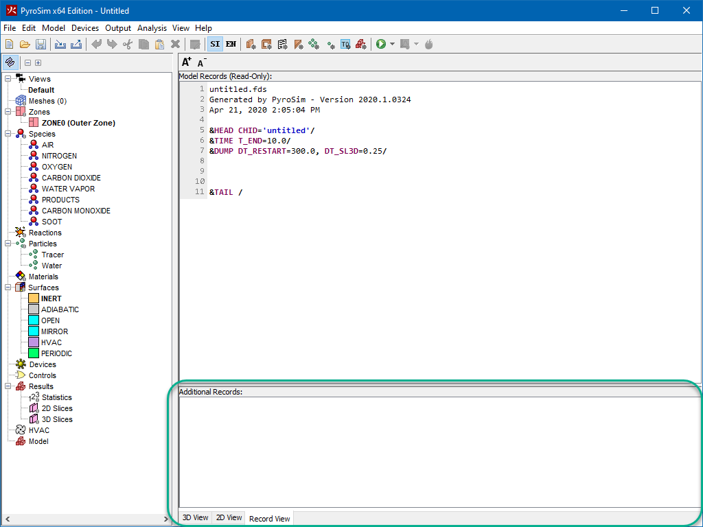
When PyroSim write the FDS input file, it copies the contents of the Additional Records Section exactly at the beginning of the FDS file.
Because PyroSim performs no validation on text in this view, it is up to the user to ensure that the statements are well-formed FDS statements and that they do not conflict with any records generated by PyroSim. In addition, none of the records written in this section can be referenced by other PyroSim objects. For instance, if a SURF record is entered in this section, it cannot be referenced by an obstruction in the PyroSim user interface. The only way to do so would be to write the obstruction in the Additional Records Section as well.
Some records, such as MISC, RADI, and others that occur once in the FDS input file can be entered in the Additional Records Section even if PyroSim has generated the record already.
For instance, if PyroSim generates the record, &MISC TMPA=30.0/, you can still enter another entry for MISC in the Additional Records Section, such as &MISC P_INF=2.0E5/.
FDS will merge these MISC records together to form &MISC P_INF=2.0E5, TMPA=30.0/.
Sometimes PyroSim may support a record but may not support it completely. For many of these records, including SURF, REAC, MATL, PART, TIME, DUMP, RADI, and MISC, PyroSim provides a way to enter additional fields. For Surfaces, Materials, Reactions, and Particles, there is an Advanced tab in the properties dialog where these additional fields may be entered, as shown in Figure 154. To enter additional fields for TIME, DUMP, RADI, and MISC, on the Analysis menu choose Simulation Parameters then choose the Misc. tab.
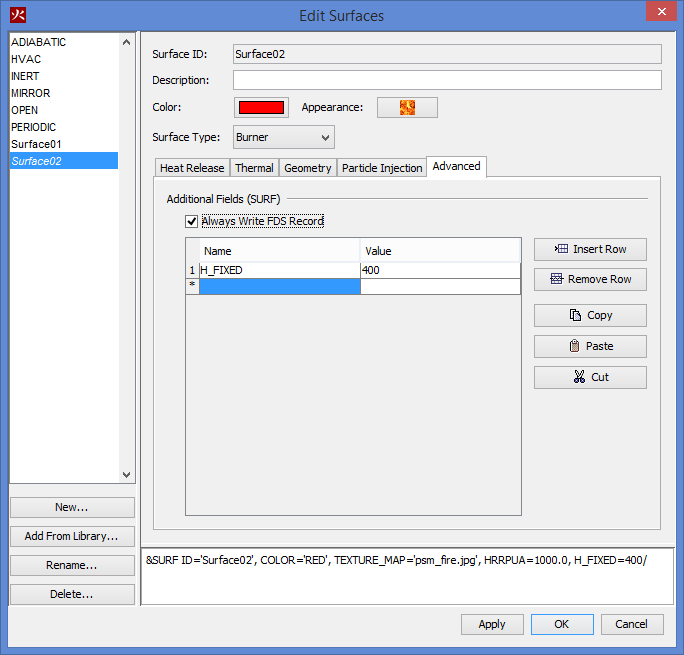
When entering additional fields, you must specify the field name and the field value. These additional fields will then be appended to the FDS record generated by PyroSim. As in the Additional Records Section, PyroSim will write these fields to the file exactly as entered in the table, so care must be taken by the user to make sure they are correct.
When PyroSim generates an FDS input file, some model objects may be ignored. PyroSim attempts to use a system of dependencies to determine whether or not a PyroSim object needs to be written out to the input file. Occasionally, this can lead to problems, especially when the Additional Records section is in use. For some objects, this default behavior can be modified by specifying that PyroSim always write the object to the input file, via the Always Write FDS Record checkbox in the Advanced tab.
With the License dialog open, as shown in Figure 155, Step 1 is to click the Online button under the 'License File' option. Step 2 is to paste the activation key that you received from Thunderhead and click OK.
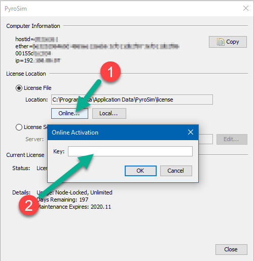
This is similar to the Online activation, except that you will click the Local button instead of "Online" and find the license file that was emailed to you from Thunderhead on your computer. This is often in Docwnloads where you saved it from the email you received.
The floating license server provides an administration web service that can assist with diagnosing many floating license problems. If the license server is installed on the local machine, the license administration server can be accessed at the following web address:
If the license server is installed on a remote machine, replace "localhost" with the name of the remote machine (i.e. the host name of the floating license server).
Once you have opened the Reprise License Server Administration page, you can use the Status commands to attempt to debug the license server problem yourself, or you can send a diagnostic report to support@thunderheadeng.com for assistance. To generate a diagnostic report:
PyroSim 2017 and newer require and updated version of the Thunderhead License Manager. You can download an updated license manager from the PyroSim download page:
https://support.thunderheadeng.com/docs/license-manager/2020-1/user-manual/
The license manager is often not installed on the same computer where PyroSim is running and instead installed on a shared server. Please review the Floating License Manager Installation guide for details on the install process.
In most cases, the newer version of the floating license manager will replace the previous version, the LIC files will be retained throughout the update process, and PyroSim will authorize against the updated server with no additional work.
If you experience trouble registering PyroSim, please contact support@thunderheadeng.com.
PyroSim utilizes many advanced graphics card features in order to provide accelerated and enhanced display of models.
Sometimes these graphics features combined with certain display drivers can cause display issues or crashes on startup. The first step in these cases is to ensure you have the latest operating system updates and graphics drivers installed. If you do and you still have display problems or crashing on startup, you can start PyroSim in Safe Mode, which disables several graphics features. To start in Safe Mode:
cmd.
Then press Enter.cd "C:\Program Files\PyroSim 2021".pyrosim -DSafeMode.If you encounter display problems or crashes, please let us know the make/model of your video card and what video driver you are using, even if Safe Mode fixes your issues. That will help us improve the software in future updates.
When running large models, it is possible that an out of memory error will be encountered. If this occurs, you can increase the default Java heap size. In our experience, the maximum size can be specified to approximately 70% of physical memory. By default, PyroSim will specify a java heap size of 50% of physical memory.
To specify the memory, you can either run from a command line or change the Start Menu shortcut properties.
To run from a command line, open a command window and then go to the PyroSim installation directory (usually C:\Program Files\PyroSim 2021).
Execute PyroSim on the command line using the -JXmx argument.
In this argument, the J specifies that the command will be passed along to the Java VM, not PyroSim.
For example, pyrosim -JXmx1200m will request 1200 MB of memory.
To edit the PyroSim shortcut properties
. Right-click on the PyroSim icon
. Select the Shortcut tab
. Edit the Target by adding a space and -JXmx1200m to the end of the Target.
A typical Target will then read C:\Program Files\PyroSim 2021\pyrosim.exe" -JXmx1200m.
MPI processes communicate using network protocols that are disabled by default for accounts without passwords. In order to work, MPI must have access to a password-protected account. Users without passwords can overcome this problem in a couple ways:
To instruct MPI to authenticate using an alternate account (e.g. set to mpi_user on a computer named aurora), you must issue a command using the console.
Microsoft Windows [Version 10.0.18363.778]
(c) 2019 Microsoft Corporation. All rights reserved.

C:\>cd "\Program Files\PyroSim {versionyear}\fds\mpi"

C:\Program Files\PyroSim {versionyear}\fds\mpi>mpiexec -remove
Account and password information removed from the Registry.

C:\Program Files\PyroSim {versionyear}\fds\mpi>mpiexec -register
account (domain\ user) [aurora\thornton]: aurora\mpi_user
password:
confirm password:
Password encrypted into the Registry.
To verify that MPI will function with the account information:
C:\Program Files\PyroSim {versionyear}\fds\mpi>mpiexec -validate
SUCCESS
PyroSim attempts to validate the MPI configuration prior to running the simulation. If this validation fails, PyroSim assumes it was because of a password mismatch. If you know this is not the case (e.g. you know you entered your password correctly), PyroSim may be responding incorrectly to a different error. To diagnose this error, please run PyroSim in safe mode. The error output should appear at the bottom of the console window. Forward this text to <support@thunderheadeng.com> and the support staff will help resolve the problem.
This indicates that MPI started successfully, but the FDS executable failed to run. To gather additional information about this error, you must run the MPI executable manually from the command prompt and observe the error output. To run the MPI executable manually, open a console window and issue the following commands:
Microsoft Windows [Version 10.0.18363.778]
(c) 2019 Microsoft Corporation. All rights reserved.

C:\>cd "\Program Files\PyroSim {versionyear}\fds"

C:\Program Files\PyroSim {versionyear}\fds>fds
The subsequent output should resemble the start of a successful FDS run; however, in this case it will probably contain error output. Copy this error output and email <support@thunderheadeng.com>, the support staff will help resolve the problem.
PyroSim has a support forum located at https://thunderheadeng.freshdesk.com/support/discussions.
If you are unable to resolve your issues from the suggestions in the table, please contact Thunderhead Engineering Email Support.
The PyroSim software is available for download from the release notes: https://support.thunderheadeng.com/release-notes/pyrosim/
The same site provides PyroSim user manuals and example problems. Please follow the examples to become familiar with the software.
Mail should be sent to:
Thunderhead Engineering
403 Poyntz Ave. Suite B
Manhattan, KS 66502-6081
USA
Due to the differences between versions 4 and 5 of FDS, it is not always possible to automatically convert legacy FDS input files and PyroSim 2006 PSM files to the new version. However, many conversions are possible and in many cases PyroSim can completely convert old input files to the new format.
PyroSim will begin the conversion process as a result of either of two actions:
In many cases, PyroSim 2015 can import records intended for version 4 of FDS that PyroSim 2006 could not. This is because PyroSim 2015 supports a broader range of FDS features than the previous version. Examples of previously unsupported version 4 features that can now be imported include solid-phase thermocouples and species.
The process for converting PSM files and FDS input files is identical. PyroSim first loads the data into a form designed to work with version 4 of FDS, then applies conversion logic to produce the corresponding data structures designed to work with version 5 of FDS. For more information about how the data is converted from a format suitable for version 5 of FDS to version 6 of FDS, see Appendix B. When PyroSim encounters a record that cannot be automatically converted, a warning message is generated. Each warning contains information about the source of the problematic record and the action taken. Some records are simply dropped and others are converted to default values. If a record is encountered that cannot be converted, but contained only default values and would not have affected the simulation, that record is dropped without issuing a warning.
Great care was taken to ensure that PyroSim generates these warnings whenever they contain important information, but not so often that they distract from important issues. When in question, PyroSim will err on the side of caution and generate a warning message. An example of this warning dialog is shown in Figure 156. If no warning dialog appears, PyroSim was able to convert the input file without encountering any compatibility issues.
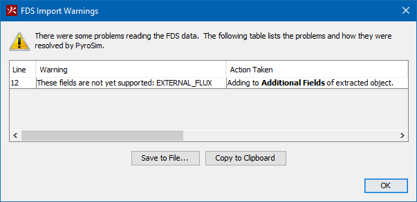
In most cases, the following records can be converted with no additional input:
The following items that can be set in the Simulation Parameters dialog of PyroSim 2006 are not supported in PyroSim 2015 and will be dropped.
All other simulation parameters will be converted to PyroSim 2015 without warnings.
All correctly specified sprinkler parameters are converted without warnings. If a sprinkler has been assigned a massless particle, however, that sprinkler will be assigned a particle with parameters from the make file, and a warning will be issued.
For FDS 4 sprinkler make files, PyroSim has a robust built-in parser that can handle both simple and complex spray patterns. The only requirement is that referenced make files must exist in the fds folder in the PyroSim install directory. PyroSim 2015 ships with the make files provided by NIST for FDS 4. If a file uses another make file, place it in this directory before importing or opening the file.
If there is a dry pipe delay greater than zero, PyroSim 2015 will create a single dry pipe with that delay and attach it to all the sprinklers in the model. Note, however, that in PyroSim 2015 the water pressure is specified per sprinkler rather than per pipe. Because of this, PyroSim will not convert the dry pipe pressure specified in the pipe record, and a warning will be issued.
To convert reaction data into a form useable by version 5 of FDS, PyroSim 2015 must reverse-engineer the fuel molecule composition based on stoichiometric coefficients. To accomplish this, PyroSim uses the equations given in section 4.4.2 of the users guide for version 4 of FDS. The result is then checked to ensure that the total molecular weight is the same as the specified molecular weight. If this check succeeds, no warning will be issued. If the test fails, PyroSim will issue a "Converted stoichiometry" warning and you must manually update reaction data to ensure accurate simulation results.
Some surface properties are converted with no additional input or warnings, including surface names, colors, and textures. The different surface types, however, undergo more complicated conversions. The following describes how PyroSim 2006 surface types are converted to Surfaces and Materials in PyroSim 2015:
Unlike PyroSim 2006, PyroSim 2015 requires that every layered surface specify a thickness \(\delta\) for each layer and that materials specify density \(\rho\), specific heat, and conductivity \(C\). In PyroSim 2006, there were a number of ways for thermally thin surfaces to either specify or omit these parameters. These surfaces allowed any one or more of \(C\), \(\delta\), and \(\rho\) to be specified in addition to \(C*\delta*\rho\). PyroSim 2015 will make a best-effort calculation of missing parameters. For instance, if \(C*\delta*\rho\) is specified along with two of the parameters, the third will be calculated; however, if more than one parameter is missing, PyroSim will use defaults for up to two of the parameters and calculate the third missing one. The default thickness for thermally thin surfaces is set to 1mm. In all cases where a default number has been assumed due to a missing parameter, a warning will be shown for the parameter.
PyroSim 2015 does not currently ship with a surface database, but users can still make their own. In fact, many different objects can now be put into a database including materials and surfaces, species, reactions, particles, and several more. As common surface descriptions and other of these object properties become available from reliable sources in a format supported by version 5 of FDS, PyroSim will again ship with a pre-filled database.
Due to the differences between versions 5 and 6 of FDS, it is not always possible to automatically convert legacy FDS input files and PyroSim 2012 PSM files to the new version. However, many conversions are possible and in many cases PyroSim can completely convert old input files to the new format.
PyroSim will begin the conversion process as a result of either of two actions: * Opening a PSM file saved with a version of PyroSim designed to work with version 5 of FDS * Importing an FDS input file designed to work with version 5 of FDS.
The process for converting PSM files and FDS input files is identical. PyroSim first loads the data into a form designed to work with version 5 of FDS, then applies conversion logic to produce the corresponding data structures designed to work with version 6 of FDS. When PyroSim encounters a record that cannot be automatically converted, a warning message is generated. Each warning contains information about the source of the problematic record and the action taken. Some records are simply dropped and others are converted to default values. If a record is encountered that cannot be converted, but contained only default values and would not have affected the simulation, that record is dropped without issuing a warning.
Great care was taken to ensure that PyroSim generates these warnings whenever they contain important information, but not so often that they distract from important issues. When in question, PyroSim will err on the side of caution and generate a warning message. An example of this warning dialog is shown in Figure 156. If no warning dialog appears, PyroSim was able to convert the input file without encountering any compatibility issues.
In most cases, the following records can be converted with no additional input:
The following items that can be set in the Simulation Parameters dialog of PyroSim 2012 are not supported in PyroSim 2015 and will be dropped.
All other simulation parameters will be converted to PyroSim 2015 without warnings.
While most reaction data can be converted easily, FDS6 does add new requirements to specify a valid reaction.
Most notable is the requirement that a Fuel Species by specified by the user.
This can be either a Predefined species, a User Defined species, or a Default species.
When the Default species type is used, a generic, non-editable species called REAC_FUEL is added to the list of species.
This species can be used the same way any other species would be, but its fields cannot be edited.
All reactions defined in PyroSim 2012 or older automatically use the Default fuel type.
It should also be noted that in FDS6 based PyroSim versions, it is required that a reaction be active in order to simulate a fire.
To make this transition easier, PyroSim automatically adds a reaction called PROPANE_REAC when converting PyroSim files that do not specify a reaction.
The PROPANE_REAC attempts to mimic the default propane reaction that is used in FDS5.
The following items will be dropped from the Reaction record:
C_EDC)Surfaces have undergone relatively few changes in from PyroSim 2012 to PyroSim 2015. However, a number of items are no longer supported in the new version.
The following records will be dropped:
POROUS = .TRUE.Unlike PyroSim 2006, PyroSim 2007 requires that every layered surface specify a thickness Delta (\(\delta\)) for each layer and that materials specify density Rho (\(\rho\)), specific heat, and conductivity (\(C\)). In PyroSim 2006, there were a number of ways for thermally thin surfaces to either specify or omit these parameters. These surfaces allowed any one or more of \(C\), \(\delta\), and \(\rho\) to be specified in addition to \(C*\delta*\rho\). PyroSim 2007 will make a best-effort calculation of missing parameters. For instance, if \(C*\delta*\rho\) is specified along with two of the parameters, the third will be calculated; however, if more than one parameter is missing, PyroSim will use defaults for up to two of the parameters and calculate the third missing one. The default thickness for thermally thin surfaces is set to 1mm. In all cases where a default number has been assumed due to a missing parameter, a warning will be shown for the parameter.
In PyroSim 2015, the interaction between particles and species has changed significantly. In PyroSim 2012, a particle could be attributed various Thermal Properties and Fuel Properties. Most of these variables have since been moved to the species object.
To handle converting legacy files, PyroSim 2015 generates a new species based on the Thermal / Fuel Properties of the legacy particle. This species is then assigned under the Liquid tab of the PyroSim 2015 particle.
The following is a list of items which are applied to the generated species:
Some items are not convertible. The following are dropped from the record:
All other items are converted properly.
McGrattan, Kevin, Simo Hostikka, Randall McDermott, Jason Floyd, and Marcos Vanella. 2021. Fire Dynamics Simulator User’s Guide, NIST Special Publication 1019. Sixth Edition. National Institute of Standards and Technology, Gaithersburg, Maryland, USA: NIST.