 |  |
General usage information for Pathfinder
There is a newer version of this document. To view the latest version, click here.
Thunderhead Engineering makes no warranty, expressed or implied, to users of Pathfinder, and accepts no responsibility for its use. Users of Pathfinder assume sole responsibility under Federal law for determining the appropriateness of its use in any particular application; for any conclusions drawn from the results of its use; and for any actions taken or not taken as a result of analyses performed using these tools.
Users are warned that Pathfinder is intended for use only by those competent in the field of egress modeling. Pathfinder is intended only to supplement the informed judgment of the qualified user.
The software package is a computer model that may or may not have predictive capability when applied to a specific set of factual circumstances. Lack of accurate predictions by the model could lead to erroneous conclusions. All results should be evaluated by an informed user.
All other product or company names that are mentioned in this publication are tradenames, trademarks, or registered trademarks of their respective owners.
Throughout this document, the mention of computer hardware or commercial software does not constitute endorsement by Thunderhead Engineering, nor does it indicate that the products are necessarily those best suited for the intended purpose.
This work was originally made possible by a Small Business Innovative Research (SBIR) grant (2005-2007) by the United States National Science Foundation.
We would like to thank Rolf Jensen and Associates for their assistance with testing and other suggestions that helped guide the development of the simulator.
We would also like to thank the users whose feedback helps us improve the software and incorporate more useful features.
Pathfinder is an agent-based egress and human movement simulator. It provides a graphical user interface for simulation design and execution as well as 2D and 3D visualization tools for results analysis.
| Intel | AMD | |
| Operating System: | Windows 10 | Windows 10 |
| Processor: | Core i5 3570 (4 core) | Athlon x4 970 (4 core) |
| Graphics Card: | Integrated HD Graphics | Integrated HD Graphics |
| Memory: | 8GB RAM | 8GB RAM |
| Intel | AMD | |
| Operating System: | Windows 11 | Windows 11 |
| Processor: | Core i7 8700 (6 Cores / 12 Threads) | Ryzen 7 1700 (8 Cores / 12 Threads) |
| Graphics Card: | NVIDIA GeForce GTX570 / AMD Radeon HD7870 | NVIDIA GeForce GTX570 / AMD Radeon HD7870 |
| Memory: | 16GB RAM | 16GB RAM |
You can download the current version, sign up for a free trial, and purchase the software from the Pathfinder Support Page. This page also provides instructions for installation and activation. Troubleshooting info can be found on the Pathfinder FAQs page. There is no functional difference between the trial version of Pathfinder and the full version, the only limitation is the trial license duration.
Administrator privileges are required to install Pathfinder. This is necessary because the installer adds processes to the operating system for license management.
If an older version of Pathfinder is present, the installer will automatically remove the older version during the installation process. License files and properties files (e.g., recently opened PTH files) from the older installation will be preserved and utilized by the updated version of Pathfinder.
Pathfinder will regularly check for and notify the user of available updates to the software when configured to do so. By default, Pathfinder will check for updates on startup and display the relevant information in the Check For Updates dialog when one is available.
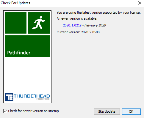
Users can also access this dialog by navigating to Help→Check For Updates
The dialog can be disabled on startup by unchecking Check for newer version on startup. Users can also elect to skip the current update by clicking the Skip Update button, which will prevent update notifications until a new version is released beyond the latest version.
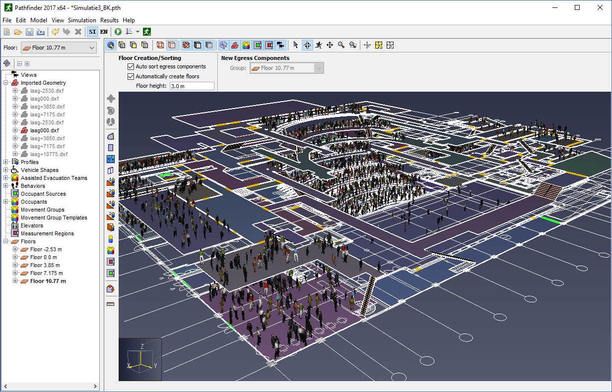
Pathfinder includes a graphical user interface that is used primarily to create and run simulation models. A screenshot of this user interface is shown in Figure 2. This screenshot displays a model of the Theater de Vest in Alkmaar, Netherlands. The model was created by Van Hooft Adviesburo. For clarity, the image shows only one of the DXF files used to create the geometry. The model includes 2177 occupants.
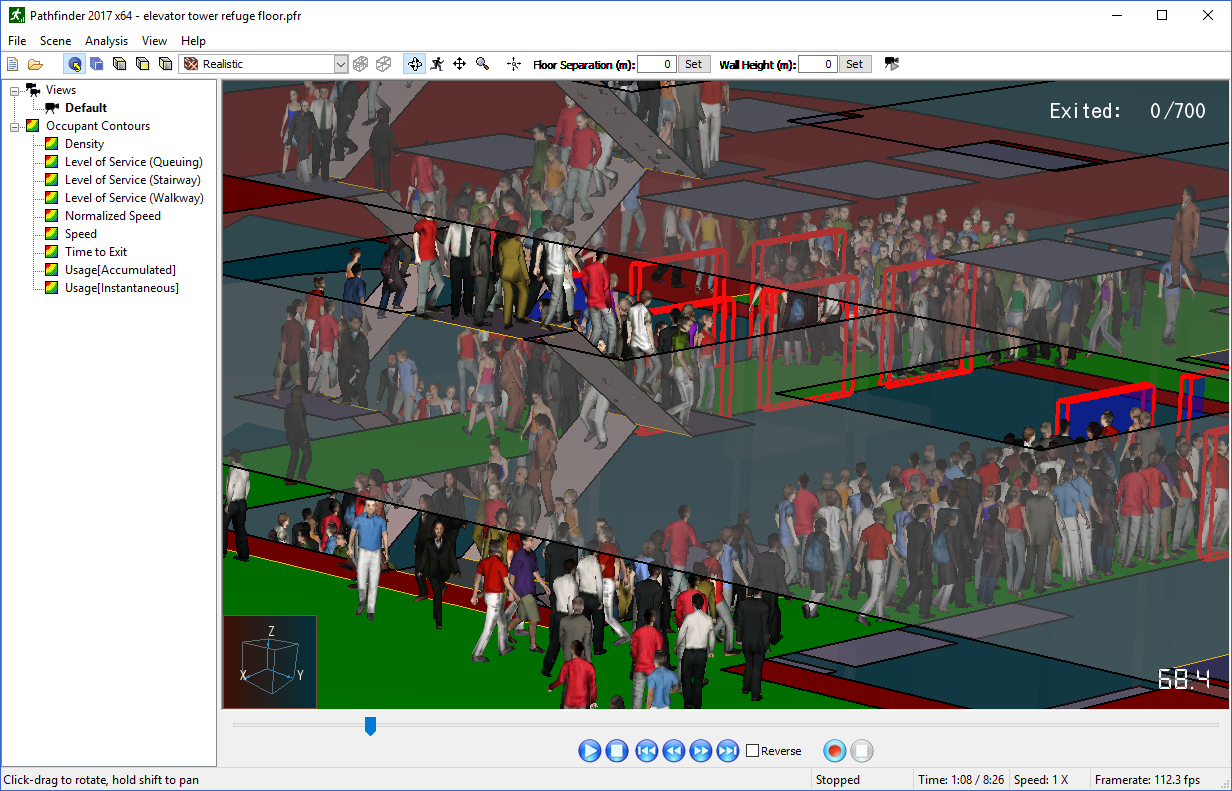
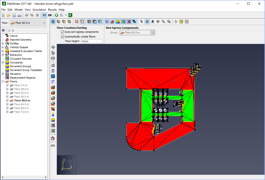
Pathfinder also includes a second program designed specifically for high-performance visualization of 3D time history. The 3D Results program is shown in Figure 3. In this image, occupants are gathering at a refuge area before proceeding to elevators. Transparency has been used to help view occupants on the refuge floor.
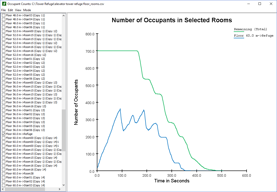
In addition to 3D visualization, Pathfinder also provides output in the form of 2D time history plots of CSV (comma separated values) out files and a text summary of room clearing times and doorway flow rates. An example time history plot can be seen in Figure 4. This plot shows the number of occupants in the refuge area and the total number of occupants in the building.
The movement environment is a 3D triangulated mesh (Figure 5), designed to match the real dimensions of a building model. This movement mesh can be entered manually or automatically based on imported data (e.g. FDS geometry).
Walls and other impassable areas are represented as gaps in the navigation mesh. These objects are not actually passed along to the simulator, but are represented implicitly because occupants cannot move in places where no navigation mesh has been created.
Doors are represented as special navigation mesh edges. In all simulations, doors provide a mechanism for joining rooms and tracking occupant flow. Depending on the specific selection of simulation options, doors may also be used to explicitly control occupant flow.
Stairways are also represented as special navigation mesh edges and triangles. Occupant movement speed is reduced to a factor of their level travel speed based on the incline of the stairway. Each stairway implicitly defines two doors. These doors function just like any other door in the simulator but are controlled via the stairway editor in the user interface to ensure that no geometric errors result from a mismatch between stairways and the connecting doors.
Elevators are called to a floor when occupants arrive at the elevator door. The elevator model includes capacity, pick-up and discharge floors, and the ability to group elevators in banks.
Each occupant is defined by position, a profile that specifies size, speed, etc., and a behavior that defines goals for the occupant. The behavior allows scripting so that, for example, an occupant may wait at a location for a specified time and then proceed to an elevator. The occupant is represented as an upright cylinder on the movement mesh and movement uses an agent-based technique called inverse steering. Each occupant calculates movements independently.
Pathfinder supports two movement simulation modes. In "Steering" mode, occupants use a steering system to move and interact with others. This mode tries to emulate human behavior and movement as much as possible. SFPE mode uses a set of assumptions and hand-calculations as defined in the Engineering Guide to Human Behavior in Fire (SFPE 2019). In SFPE mode, occupants make no attempt to avoid one another and can interpenetrate, but doors impose a flow limit and velocity is controlled by density. You can freely switch between the two modes within the Pathfinder user interface and compare answers.
More information about both modes is provided in the Pathfinder Technical Reference (Pathfinder Technical Reference, n.d.).
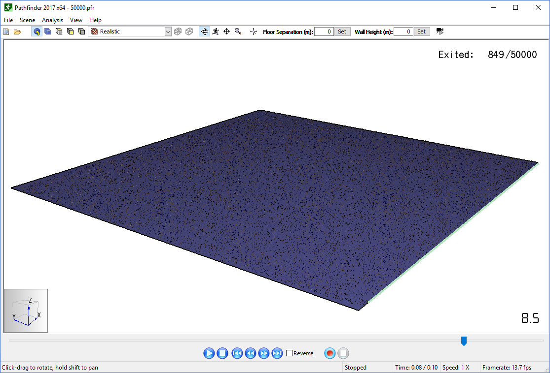
System requirements depend on the type of model being analyzed. To illustrate this, two different models (Table 3) were evaluated using a laptop running 64-bit Windows 8 Pro with an Intel Core i7 2.60 GHz processor, 8 GB of RAM, and NVIDIA NVS 5200M graphics card. The first model (Figure 6) had a single room with 50,000 occupants and did not include any imported geometry. The second model (Figure 7) imported a relatively complex Revit model to create the Pathfinder model and had 3,000 people.
The key parameters are the number of people in the model and the model complexity, measured by the number of navigation mesh triangles used in the Pathfinder solution and the number of imported Revit primitives (triangles). The simple model had only 4 triangles, with the consequence that the movement calculation of the path for each person is simple and that display performance is related to the drawing of people. The Revit model had 21,480 triangles for the navigation mesh but over 1,300,000 triangles for the Revit geometry.
The model with 50,000 people (Figure 6) solved in about 18 minutes, while the Revit model with 3,000 people (Figure 7) took about 5 minutes. The graphical display performance for the model with 50,000 people was responsive at 15 frames/sec, while the Revit model with the imported geometry displayed was slow at 5 frames/sec. When only the Pathfinder navigation mesh was displayed, the Revit model was responsive.
| |
| Parameter | Model | |
|---|---|---|
| People | Revit Import | |
| Number of occupants | 50,000 | 3,000 |
| Number navigation triangles | 4 | 21,480 |
| Number Revit face primitives | 0 | 1,300,000 |
| CPU solution time (s) | 1090 | 297 |
| Navigation mesh display rate (fps) | ~15 | ~70 |
| Imported geom display rate (fps) | n/a | ~5 |
The minimum requirements to run Pathfinder include:
For a balanced performance we recommend:
Revit models place a premium on graphics capability. We have found that mid-cost gaming graphics cards (GeForce GTX 570 / Radeon HD 7870 or equivalent) allow us to display relative large Revit models with good performance. Benchmarking sites that we find useful to compare CPU and graphics card performance can be found at: http://www.cpubenchmark.net/ and http://www.videocardbenchmark.net/.
Pathfinder stores data related to user preferences in a file called Pathfinder.props. By default, this file can be found in one of:
%APPDATA%\Pathfinder\Pathfinder.props%PROGRAMDATA%\Pathfinder\Pathfinder.props
If at least one of these files exists, Pathfinder will load the user preferences.
If both files exist, Pathfinder will load user preferences from both files, giving preference to the file located in the APPDATA folder.
This way the preference file located in the PROGRAMDATA folder can be shared among multiple machines, and the file located in the APPDATA folder on each machine overrides the shared settings.
The PROPS file is stored in a plaintext format, and can be viewed or edited with any conventional text editor.
While it is not recommended to edit the file directly, some troubleshooting techniques may involve deleting the PROPS file so that a new one can be created from scratch by Pathfinder.
Thunderhead Engineering
403 Poyntz Avenue, Suite B
Manhattan, KS 66502-6081
USA
Sales Information: sales@thunderheadeng.com
Product Support: support@thunderheadeng.com
Phone and Fax: +1.785.770.8511
Pathfinder provides three main views for working on evacuation models: the 2D View, 3D View, and Navigation View. These views represent your current model. If an object is added, removed, or selected in one view, the other views will simultaneously reflect the change. Each view is briefly described below.
The Navigation View helps you quickly find objects and data that are not always easily accessible from the 3D and 2D views.
The Navigation View is arranged in the following groups:
The buttons directly above the Navigation View perform the following actions:
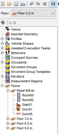
The Floor selection box above the Navigation View panel (see the top of Figure 8) can be used to manage floors. Any time a room, stair, ramp, or door is created it is added to a floor group matching the current selection in the Floor box. Changing the selection in the Floor box will cause the newly selected floor to be shown and all other floors to be hidden. Also, the Z property for all drawing tools will automatically default to the height of the floor currently selected in the Floor box. The visibility of any object or group of objects can always be manually set using the right-click context menu. This technique is useful if you want to show two floors at the same time (e.g. when creating a stairway).
The 3D and 2D views as shown in Figure 9 are the main views in which drawing is performed in Pathfinder.
Both views contain tools to draw egress geometry and navigate in a model.
The main difference between the two views is that the 3D view allows the model to be viewed from any direction, whereas the 2D view only allows viewing from one, orthographic direction.
In addition, the 3D view contains no snap grid, whereas the 2D view does.
The 3D view is entered by selecting the perspective camera, ![]() , and the 2D view is entered by selecting one of the orthographic cameras,
, and the 2D view is entered by selecting one of the orthographic cameras, ![]() ,
, ![]() , or
, or ![]() .
.
At the top of the view is several buttons that show different camera modes, display options, and navigation modes. The panel under this is known as the Property Panel and is a selection context-sensitive panel. If a drawing tool is selected, it will show properties that can used to help draw. If no drawing tool is selected, and an object or several objects are selected, this panel will show the properties relevant to the selection. The panel of buttons on the left shows move/copy and drawing tools. The small panel at the bottom displays messages relevant to the current tool.
Several tools are provided for navigating through the model in the 3D view, including orbit, roam, pan, and zoom tools.
The main navigation tool for the 3D view is the Orbit tool, ![]() .
.
Another navigation tool in the 3D view is the Roam tool, ![]() .
This tool allows the camera to move in and out of the model at will.
It has a higher learning curve but is the most flexible viewing tool because it allows the camera to be placed anywhere in the model.
This tool can work in three different modes.
In the first two modes, the movement speed of the camera can be changed by holding CTRL and spinning the mouse wheel up or down.
Spin it up to increase the speed and down to decrease the speed.
.
This tool allows the camera to move in and out of the model at will.
It has a higher learning curve but is the most flexible viewing tool because it allows the camera to be placed anywhere in the model.
This tool can work in three different modes.
In the first two modes, the movement speed of the camera can be changed by holding CTRL and spinning the mouse wheel up or down.
Spin it up to increase the speed and down to decrease the speed.
This mode smoothly animates the camera to any location using only the mouse. To do so, press and release the middle mouse button. The cursor will disappear, and the tool will enter Mouse-only Mode. In this mode, moving the mouse will look around as in the other modes except that the mouse button doesn’t have to be pressed. Pressing and dragging the left mouse button will move the camera in the XY plane. The further the mouse is moved from its button press, the faster the camera will move. This can simulate the effect of accelerating the camera. Doing the same with the middle mouse button will cause the camera to move forward/backward in the XY plane with changes along the Y mouse axis and turn left/right with changes along the X mouse axis. Pressing and dragging the right mouse button will move the camera along the Z axis in the same manner. To exit Roam Mode, press and release the middle mouse button again or press Esc on the keyboard.
The other navigation tools include a Pan/Drag tool, which moves the camera left and right and up and down, a zoom tool, which zooms in and out of the model while click-dragging, and a zoom box tool, which allows a box to be drawn that specifies the zoom extents.
Pathfinder can also be navigated while using the Selection/Manipulation tool, ![]() .
To Orbit the camera while in perspective view, use a right-click and drag combination.
Similarly, use a middle-click and drag to Pan in perspective view.
.
To Orbit the camera while in perspective view, use a right-click and drag combination.
Similarly, use a middle-click and drag to Pan in perspective view.
Navigation in the 2D view is simpler than in the 3D view. The selection tool not only allows objects to be selected if single-clicked, but it allows the view to be panned by middle or right-clicking and dragging, and the view to be zoomed by using the scroll wheel. The drag and zoom tools are also separated into separate tools for convenience.
At any time, the camera can be reset by pressing CTRL+R on the keyboard, or selecting Reset All tool, ![]() .
This will cause the entire model to be visible in the current view.
For all navigation tools but the Roam tool, reset will make the camera look down the negative Z axis at the model.
For the roam tool, however, reset will make the camera look along the positive Y axis at the model.
.
This will cause the entire model to be visible in the current view.
For all navigation tools but the Roam tool, reset will make the camera look down the negative Z axis at the model.
For the roam tool, however, reset will make the camera look along the positive Y axis at the model.
The camera can also be reset to the current selection at any time by pressing CTRL+E. This will cause the camera to zoom in on the selected objects and the orbit tool to rotate about the center of their bounding sphere.
Very similar to resetting the camera, the view can be fit by pressing F on the keyboard or selecting the Fill View tool, ![]() .
The difference between the Fill View and Reset All tools is that filling the screen does not change the view angle of the camera.
Instead the camera will recenter/rezoom to fit the screen.
.
The difference between the Fill View and Reset All tools is that filling the screen does not change the view angle of the camera.
Instead the camera will recenter/rezoom to fit the screen.
Drawing can be performed in both the 3D view and the top 2D view. The 3D view allows the user to see the model from any angle, but most tools restrict drawing in the XY plane. The top view completely restricts drawing to the XY plane, but it also displays an optional snap grid. The snap grid size can be set under Edit snap grid in the View menu, and it can be turned off by deselecting Show Snap Grid in the View menu.
Drawing is performed in one of the two following modes:
At any time while drawing, the user can press ESC, which causes the current object to be cancelled and the previous navigation tool to be selected.
For each tool there are often two ways to create its object.
The property panel will update the graphical preview immediately to reflect changes in the input. This allows fine-grained control in creating the object. The individual drawing tools are discussed in Creating Movement Space.
While using any of the draw tools, the mouse can still be used to zoom or pan the camera as follows:
Snapping is one way to precisely draw and edit objects. It is the process of finding some element in the scene, such as a vertex or edge close to the cursor, and snapping the cursor to that element like a magnet.
In Pathfinder, snapping can be performed against objects in the model and orthographic constraints. The 2D View additionally provides a sketch grid and polar (angle) constraints. If a snap point is found, an indicator dot, shown in Figure 10, will appear at the snap point.
By default, snapping is enabled. It can be disabled by holding ALT on the keyboard while using a drawing/editing tool.
Pathfinder provides a user-defined drawing grid, or sketch grid, in the 2D View.
When a new model is created, the sketch grid is visible and can be snapped to in the 2D view.
The default spacing for the divisions is .5 m, but can be changed by going to the View menu and clicking Edit Snap Grid.
To disable grid snapping, on the View menu uncheck Show Snap Grid.
All objects displayed in the model can be snapped to when using the drawing/editing tools. There are three basic categories of geometry that can be snapped to on objects: faces, edges, and vertices. Objects can have any combination of types. If there are multiple types close to the cursor, Pathfinder will give vertices precedence over edges and edges precedence over faces.
Constraints are dynamic snapping lines that are only visible when the cursor is near them. They appear as infinite dotted lines that extend from the most recent relevant clicked point when using a multi-point tool.
Pathfinder contains two types of constraints:
15 degree increments from the current view’s local X axis.If the cursor is currently snapping to a constraint, that constraint can be locked by holding SHIFT on the keyboard. While holding SHIFT, a second dotted line will extend from the cursor to the locked constraint (the first dotted line). This is useful for lining up objects along a constraint with other objects.
Snapping behavior may change depending on which modeling tool is selected and whether a 2D or the 3D view is active. If the 3D view is active, the cursor will snap to a 3D coordinate, which may then be further restricted by the tool. For instance, the occupant dropper tool (see Individual Placement) may first snap to a 3D coordinate and then project that coordinate down along Z onto the nearest room. If a 2D view is active, the cursor may first be snapped to a 3D coordinate, and then projected onto a drawing plane that is parallel to the camera’s view plane. Most tools will indicate the snapped position in the status bar at the bottom of the 2D or 3D view.
Snapping may be a slow operation in complex models. In these cases, asynchronous snapping is used to keep the cursor and application responsive while the snapping operation takes place in the background. During asynchronous snapping, a wait cursor will appear at the cursor crosshairs while the snapping completes. While this takes place, either keep the cursor still to allow the current snapping operation to complete or move the cursor to abort the operation and snap to a different location. Asynchronous snapping can be disabled by unchecking File→Preferences→Enable asynchronous snapping. Note that if it is disabled, the cursor may briefly hang and the application will become unresponsive while these long snapping calculations take place.
Pathfinder provides a variety of view options for displaying both navigation geometry and imported geometry that can also aid with drawing. This includes options for rendering geometry, displaying agents, coloring rooms, and setting the transparency of rooms.
In the toolbar above the properties window in the 2D and 3D views, there is a drop-down as shown in Figure 11 and buttons as shown in Figure 12 that control how geometry is rendered.
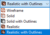
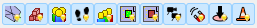
From left to right, the buttons are:
Occupants can be displayed using a number of options. They can be viewed as simple shapes, including disks and cylinders. They can also be displayed as the artist’s mannequin or as their respective human avatars specified in their profiles. These options are available under View menu and Occupant Display submenu.
When occupants are not viewed as people, they can also be colored in several ways, available under View→Occupant Color:
Rooms can be colored in a variety of ways. All coloring options are available under the View menu and Color Rooms submenu. Rooms can be colored by the following options:
number_of_occupants/room_area.
Red indicates high density and blue indicates low density.Sometimes it is useful to be able to see through rooms and stairways, such as when drawing on top of an imported background image. To change the opacity of a set of components, select them and in the property panel, change the opacity. Opacity settings will carry through to 3D results visualization.
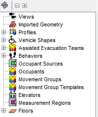
The main method of organization in Pathfinder is to use groups. In every model there are already some implicit groups that cannot be modified, including Views, Imported Geometry, Profiles, Vehicle Shapes, Assisted Evacuation Teams, Behaviors, Occupant Sources, Occupants, Movement Groups, Movement Group Templates, Elevators, Measurement Regions, and Floors as shown in Figure 13. Sub-groups can be created to further organize the model as discussed in the following sections.
Sub-groups can be created under all groups (floors are discussed in Floors.) Groups can also be created in other sub-groups.
To create a new group:
An object can be moved from one group to another at any time.
To change an object’s group:
By default, Pathfinder uses a variety of keyboard shortcuts that are standard to Windows and Java applications. To accelerate model creation, shortcuts can be added or changed to in a variety of ways.
Some keyboard shortcuts are used by Java UI components. If a shortcut does not result in the expected behavior, it may be in direct conflict with a preexisting Java shortcut. It is best practice to avoid these conflicts (Default Swing key bindings (IBM n.d.)).
The Keyboard Shortcut Editor Window can be found in the File→Preferences dialog and clicking Edit Actions and tools can are bound to a combination of modifier keys (ALT, CTRL, SHIFT, etc.) and other key presses.
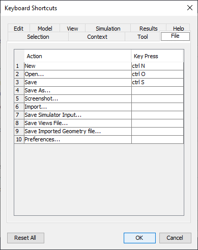
The dialog is split into sections similar to those used in the Pathfinder toolbar menus. There are additional tabs for shortcuts related to tool activation, object selection, and context sensitive actions.
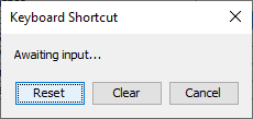
To change a shortcut, click on cell in the Key Press column and a window launches (Figure 15) with four different options.
There are times when a set of objects might need to be selected or a distribution of discrete items specified. Pathfinder provides two dialogs that can be used to do so.
When specifying a set of items, such as the doors an occupant is allowed to use, the Figure 16 is shown.
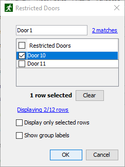
The list in this dialog shows the items in the model that can be chosen. Click the checkbox next to the item in the list to select the item. Alternately, click the checkbox in the header of this list to select or deselect all items currently displayed in the list.
Click OK to commit the selected items.
Sometimes, the list of items might be quite long, making it difficult to quicky find the desired items.
There are several ways to limit the displayed items, however.
At the top of the dialog is a search field.
Typing in this field will limit the list of items to only those that partially contain the entered text.
To match the name of an object exactly, surround the text with quotes.
For example "Door01" will show only the doors that have exactly the name, Door01.
This search field also allows wildcards including the following:
For example, typing Door?1 would find objects with the following names: Door01, Door51a, Exit Door91 (south), etc.
It would not, however, find the following:
Door001, Door9221, etc.
Typing Door*1, however, would find those.
Another way to limit the displayed item is to check the box next to Show only selected rows. This will only show items that have already been selected. By default, when the Set Chooser dialog opens, if there are selected items in a long list, Show only selected rows will be automatically selected so it’s easy to see the current selection.
The following additional options are also available:
Pathfinder also allows discrete distributions of objects in certains cases. For example, the Change Behavior action allows occupants to change their behavior by choosing a random behavior from a discrete distribution. Occupants might have a 30% chance of choosing Behavior01 and 70% chance of choosing Behavior02. The Figure 17 allows these distributions to be specified.
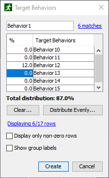
In this dialog, the probability of choosing a value can be entered into the first column. The second column shows the name of each available item. The sum of the values in first column must add to 100%.
As in the Set Chooser dialog described above, the displayed items can be filtered either by typing text into the search field at the top of the dialog or by clicking Display only non-zero rows, which only shows rows that have non-zero probabilities. In addition, Show group labels can be checked to show the names of the groups next to the item names in the list, such as "BehaviorGroup01→Behavior01".
The distribution dialog has some additional actions that can be used to clear values or distribute probabilities evenly among several items.
To set the probability of multiple items to 0.0%, click the Clear button and choose from one of the following options in the popup menu:
To distribute probability evenly across multiple rows, click the Distribute Evenly button and choose one of the following option in the popup menu:
X% to selected rows100%.
It will distribute all remaining values to those currently highlighted in the list.
For instance, if the current total distribution is 85%, and there are 3 highlighted items in the list, this action will add (100 - 85)/3 = 5% to each selected item’s current probability, ensuring that the end total distribution is 100%.X% to displayed rows100% to selected rows100% across only those that are highlighted.100% to displayed rows100% across those currently displayed in the list.100% to all rows100% across all rows, including hidden rows.Pathfinder is built on the idea of creating floor space on which occupants can walk. Every navigation component drawn in Pathfinder is some piece of flooring that can be travelled on, which can range from floors, to doorways, to stairs. Obstructions exist as holes in the floor.
The main egress components include rooms, which are empty floor spaces bounded by walls, doors, which connect rooms on the same level, stairs/ramps, which connect rooms on different levels, and elevators, which connect multiple levels.
To organize egress components, Pathfinder provides the concept of floors, which group together components at different Z locations.
Floors are the primary method of organization in Pathfinder. At their most basic level, they are simply groups in which rooms, doors, stairs, ramps, and exits can be placed, but they also control the drawing plane for most tools and filtering of imported geometry.
In every Pathfinder model, at least one floor must exist, and at any given time, there is one active floor. Whenever any navigation object is drawn, it will either be placed in the active floor or a subgroup of the active floor.
By default when a new model is started, there is one floor at Z=0, and additional floors are either created automatically depending on where the geometry is drawn or manually created.
In addition, new navigation components are automatically sorted into the appropriate floor when drawn.
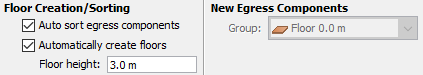
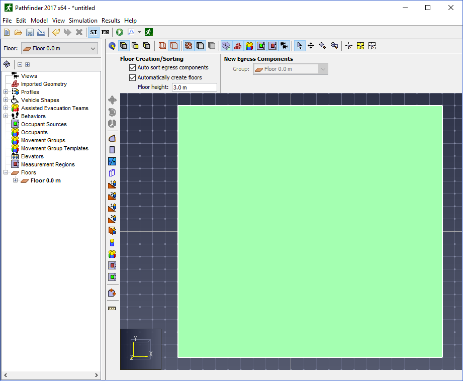
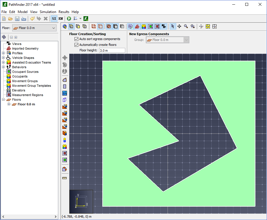
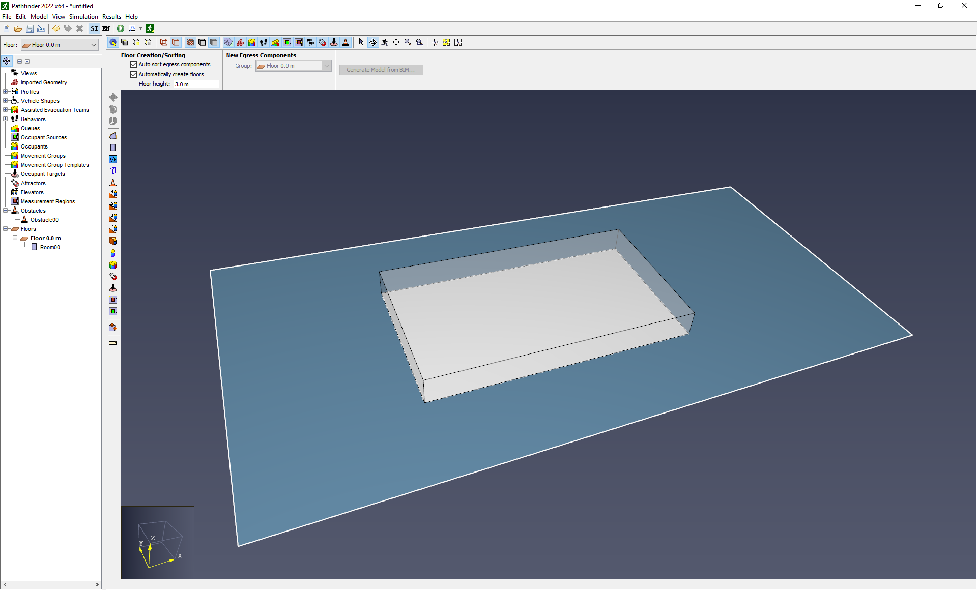
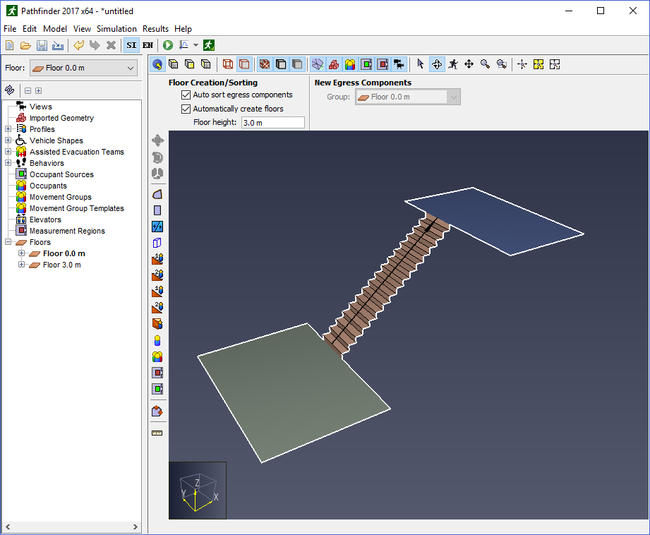
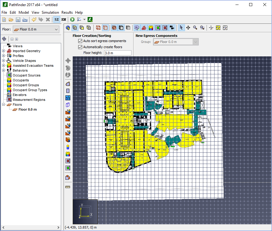
When nothing is selected in the model, the Floor Creation panel is shown, as in Figure 18. This panel controls the automatic creation of floors and automatic sorting of new objects into floors.
The following scenario demonstrates how objects are organized when auto-sort and auto-floor-creation are enabled (organization of the model is shown in Figure 19):
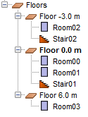
In this example, only rooms and stairs were created. The floors were automatically created and the rooms and stairs were automatically sorted into the appropriate ones.
Automatic floors can be created and components sorted into the floors by performing the following:
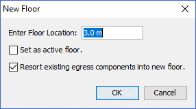
Floors can also be created manually at any time.
There are two other options in this dialog:
By default, the name of the floor is Floor \(x\) where \(x\) is the working plane of the floor.
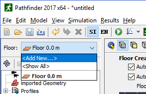 |  |
To change the active floor, click the floor drop-down box as shown in Figure 20, and select the desired floor. This will make that floor active and all other floors non-active.
Whenever the active floor is changed, the following additional changes take place in the model:
To show all floors click the floor drop-down box as shown in Figure 20, and click <Show All>.
This will additionally show all occupants on the floors and all sub-objects of the floors groups, and it will set the import filter to the union of all the floors' filters.
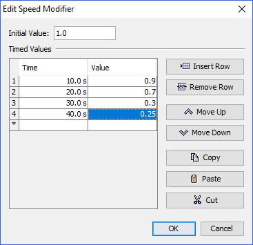
To edit a floor’s properties, first select the desired floor. The property panel as shown in Figure 22 will appear, showing the floor’s name, its Working Z location, and the Z clipping planes (Z Min Filter and Z Max Filter) for imported 3D geometry.
It also shows some statistics of the floor including the total area of the floor (Area), number of people on the floor (Pers) and density of people. Refuge Area and Speed Modifier are discussed in Room Properties.

CURR_FLOOR.
If it is CURR_FLOOR, then the clipping plane is set to the working Z location if there are any floors below this floor or \(-\infty\) if there are no floors below.NEXT_FLOOR.
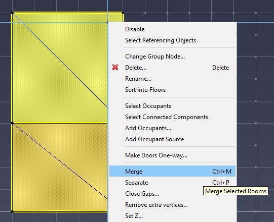
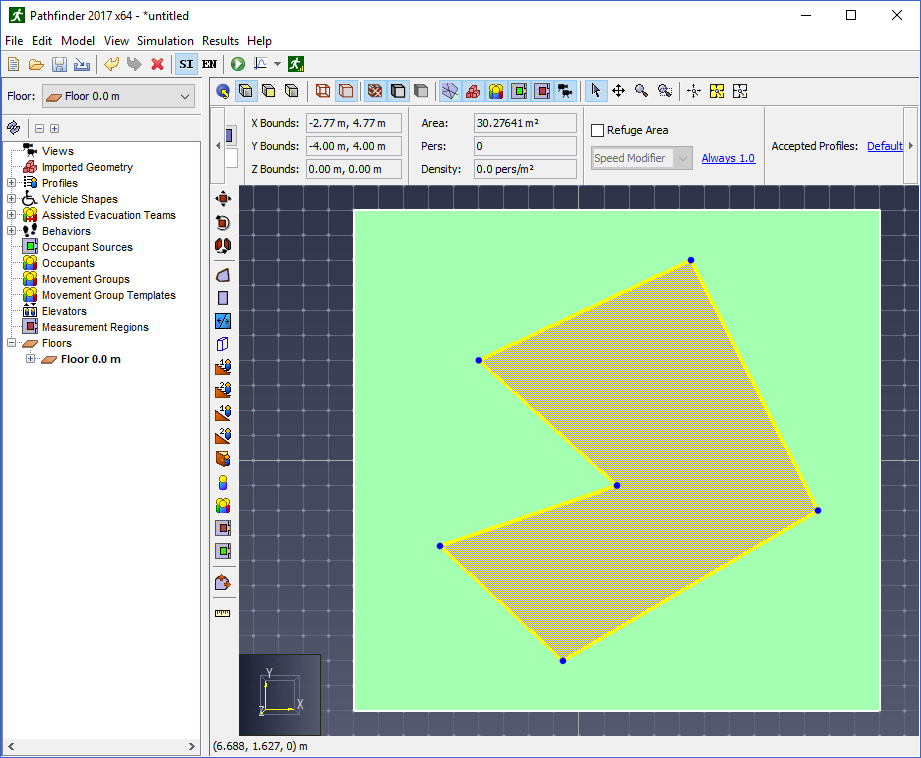
If it is NEXT_FLOOR, then the Z plane is set to the working Z plane of the next higher floor if one exists, or \(+\infty\) if there are no higher floors.Rooms are open space on which occupants can freely travel. Each room is bounded on all sides by walls. Rooms can be drawn so that they touch each other, but an occupant can only travel between them if they are connected by a door. Only one room can occupy a given space at any time, so if one room is drawn overlapping another, the overlapping area will be subtracted from the old room and given to the new. Rooms can also be merged into one, separated into constituent parts, and have internal, thin boundaries drawn in them. These features are discussed in the following sections.
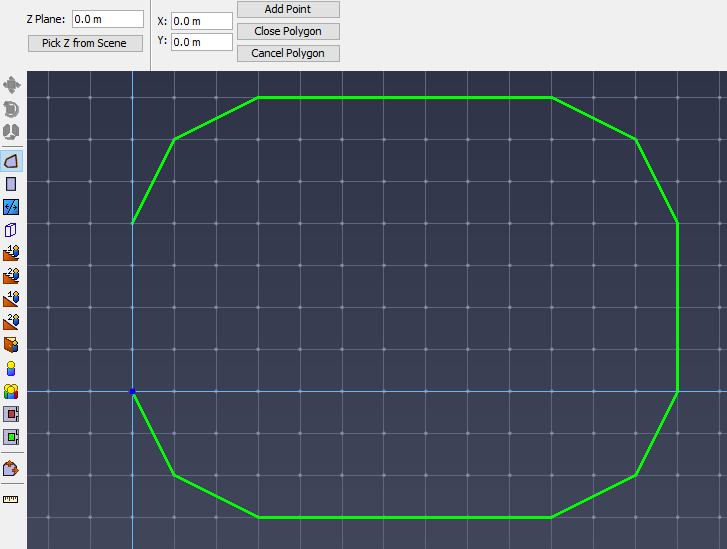
Pathfinder provides two tools for adding new room geometry:
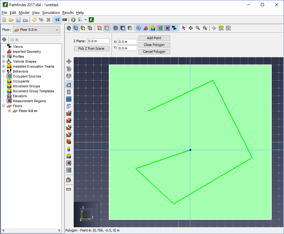
Left-click anywhere in the model to set the first point, and continue left clicking to add more points to the polygon. When at least three points are defined, right-clicking will close the polygon and complete the shape.
Alternatively, X,Y coordinates can be entered from the keyboard with the Add Point and Close Polygon buttons from the property panel.
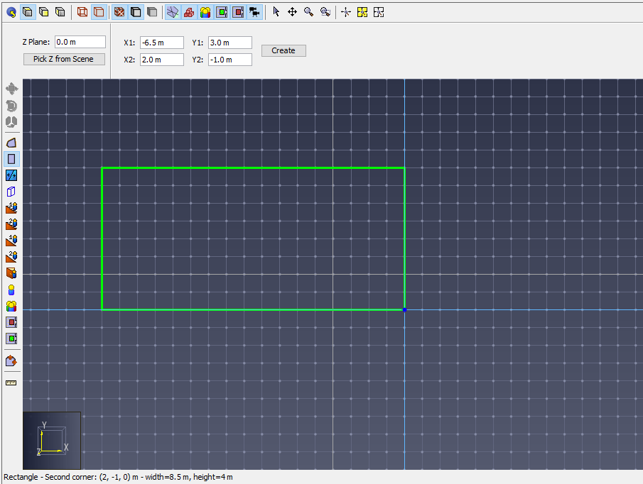
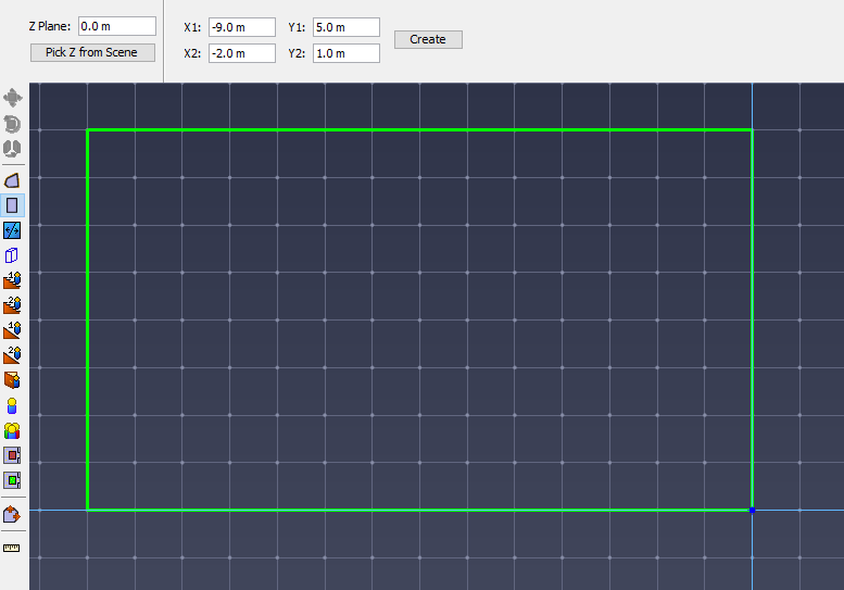
The rectangular area can also be created by entering coordinates for two points in the property panel and clicking Create.
In addition to creating new areas, both of these tools can be used on existing geometry to create negative areas. Creating new geometry over existing areas removes any interfering portion from those areas. The newly created geometry can then be deleted, leaving the negative space behind. This is discussed further in the section, Arbitrarily-shaped obstructions (desks, tables, etc.).
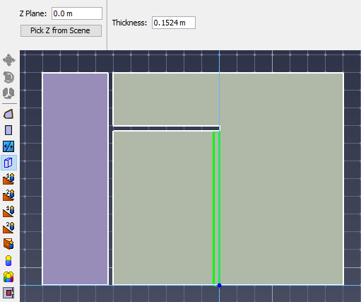
Each room tool draws on a particular Z plane that is specified in the property panel for the tool as shown in Figure 25.
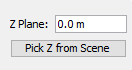
The Z plane can be specified either manually by typing the location into the Z Plane field or by picking the location from the 2D View or 3D View as follows:
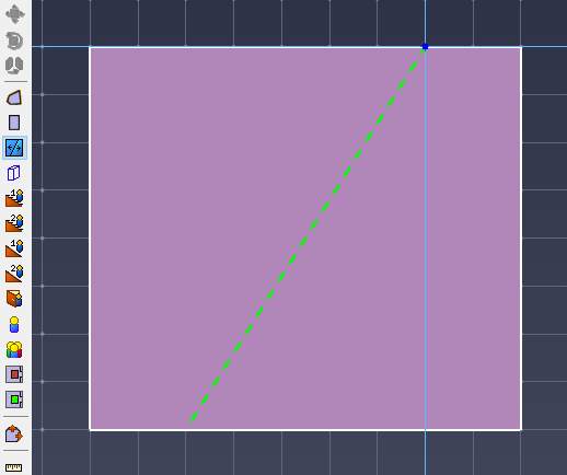
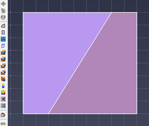
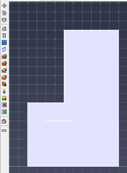
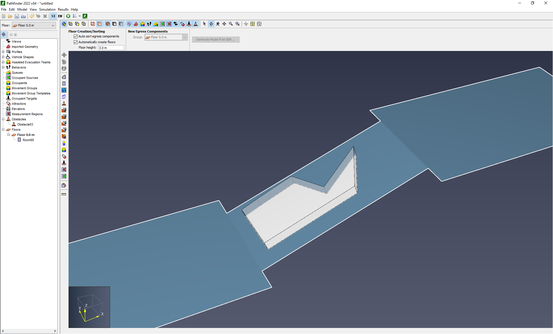
Rooms can be split into two or more pieces using the Thin Wall tool. To do this, specify the two points such that they are on the outermost boundary of the room to be divided. The original geometry will be divided into two or more new rooms with that line as the boundary between them as shown in Figure 27.
 |  |
In addition to dividing rooms, Pathfinder has two additional means to aid in creating more complex room geometry.
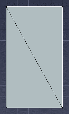
To Merge rooms:
 |  |
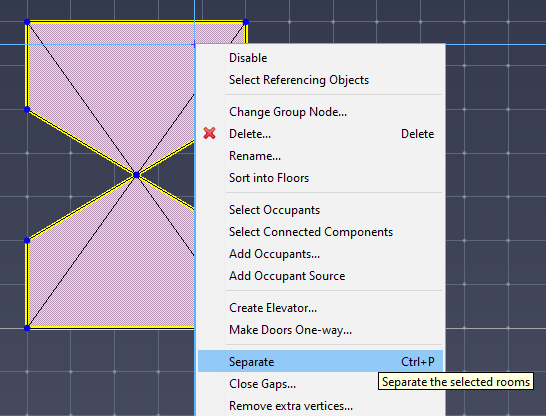
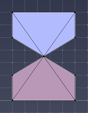
To Separate a room:
 |  |
To view and edit room properties, select a room. Its properties will be displayed in the property panel as shown in Figure 32.

The material to display on the object when the Realistic option is selected.
If a material is selected, the Color and Opacity settings below are only used if the Diffuse/Albedo coloring option for the material is set to From Object Color (see Materials).
Clicking the material button will open the Material Dialog as shown in Figure 97.
In this dialog, the material can either be edited or a new material can be applied to the object by selecting one from the list on the left and clicking the OK button.
To remove the reference to the material, select the <No Material> option from the material list.
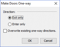
In some cases, such as modeling seating rows or shops in a mall, it may be desirable to only allow occupants to exit the room and not cross through it. This can be accomplished by making all the doors connected to the room one-way (see Doors) and ensuring that their directions point out of the room. Pathfinder provides a tool to make this easy. Instead of individually setting the one-way status of all the connecting doors, perform the following:
Pathfinder will automatically calculate the correct directions for the doors to make the rooms exit-only or enter-only.
Pathfinder performs automatic mesh optimization. An example of mesh optimization is removing multiple vertices in a straight line, or removing extra vertices left over after merging rooms. In some cases, it might be beneficial to disable mesh optimization.
To disable mesh optimization, select Preferences from the File menu, and uncheck Optimize Navigation Geometry.
In Pathfinder, obstructions that permenantly block flow are modeled as holes in the navigation geometry. Holes can be created with an arbitrary polygonal shape or as thick walls.
To model an obstruction (e.g. an office desk or other standing obstacle) within a room, the subtractive property of rooms is used. This means that the room containing the obstruction must already exist.
To create the obstruction:
 |  |
 |  |
Thin, internal walls or boundaries can be added to rooms with the Thin Wall tool ![]() .
.
To use this tool, click two points in the model as shown in Figure 39. Pathfinder will attempt to connect these two points with an internal boundary edge.
The wall tool ![]() is used to make rectangular obstructions in existing geometry (Figure 40).
is used to make rectangular obstructions in existing geometry (Figure 40).
To make a thick wall:
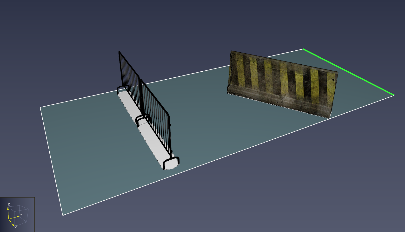
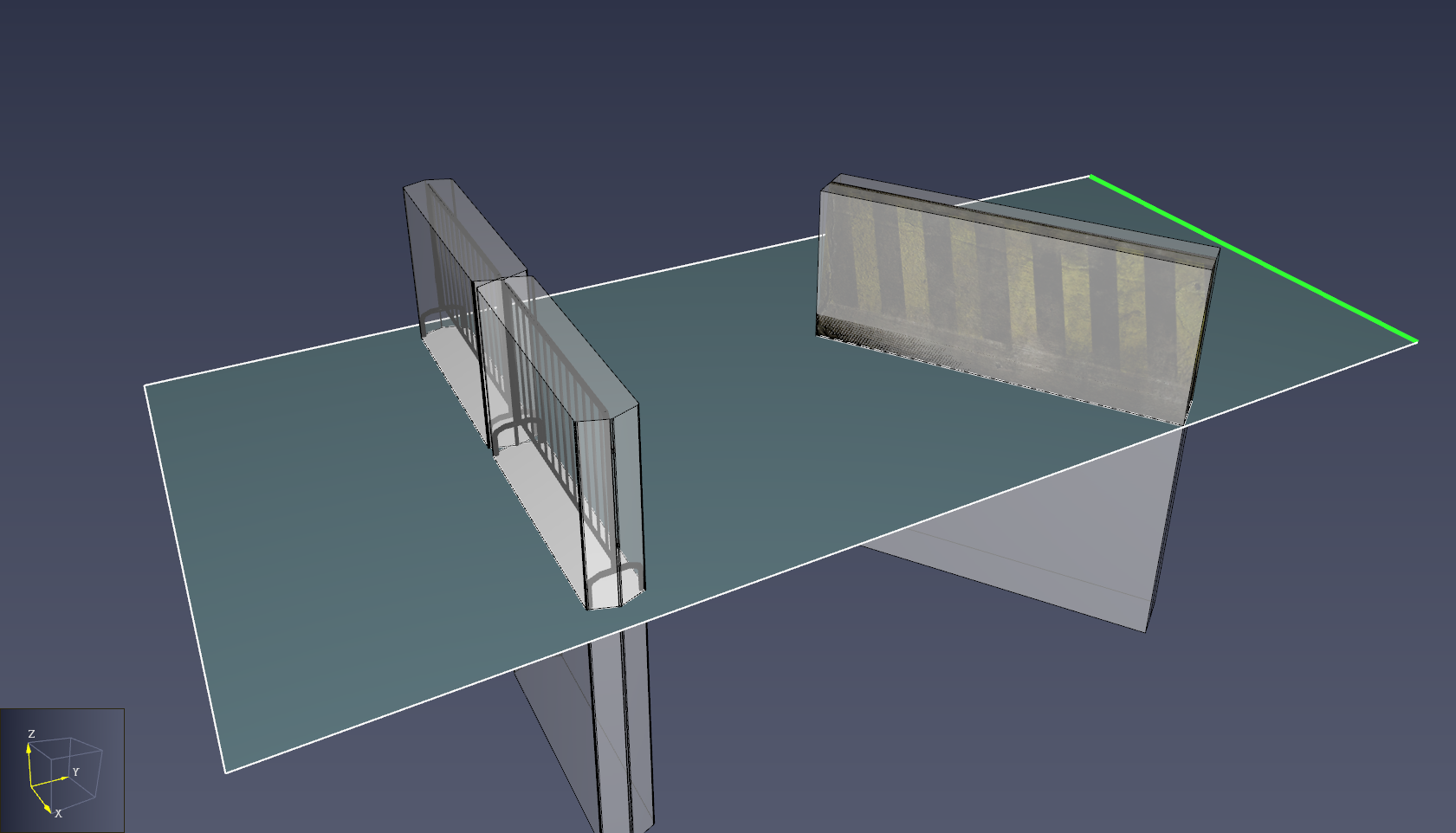
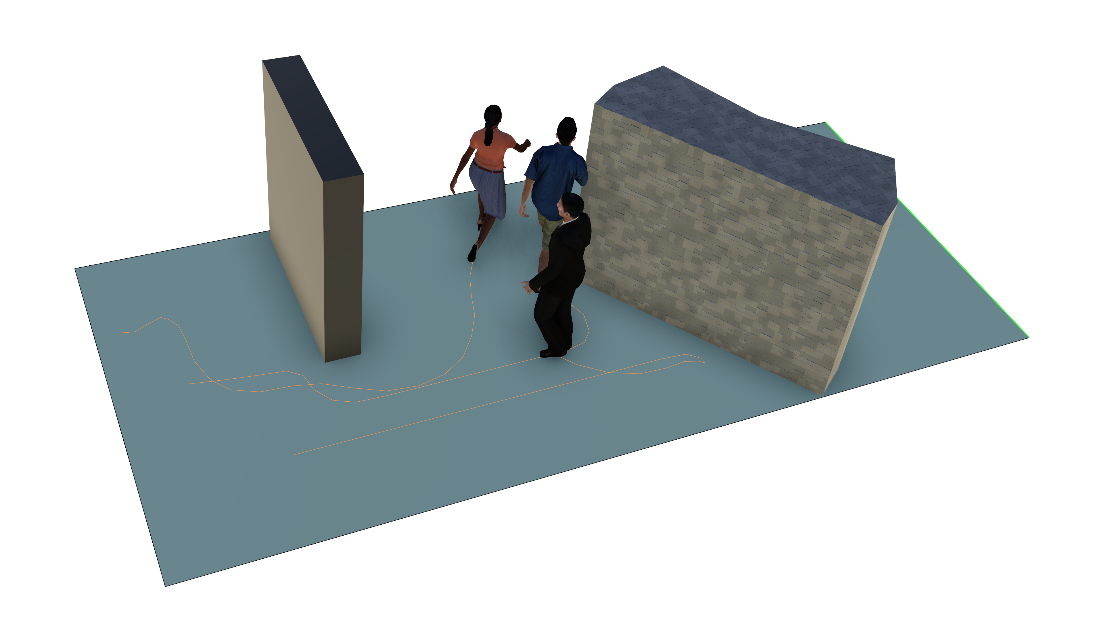
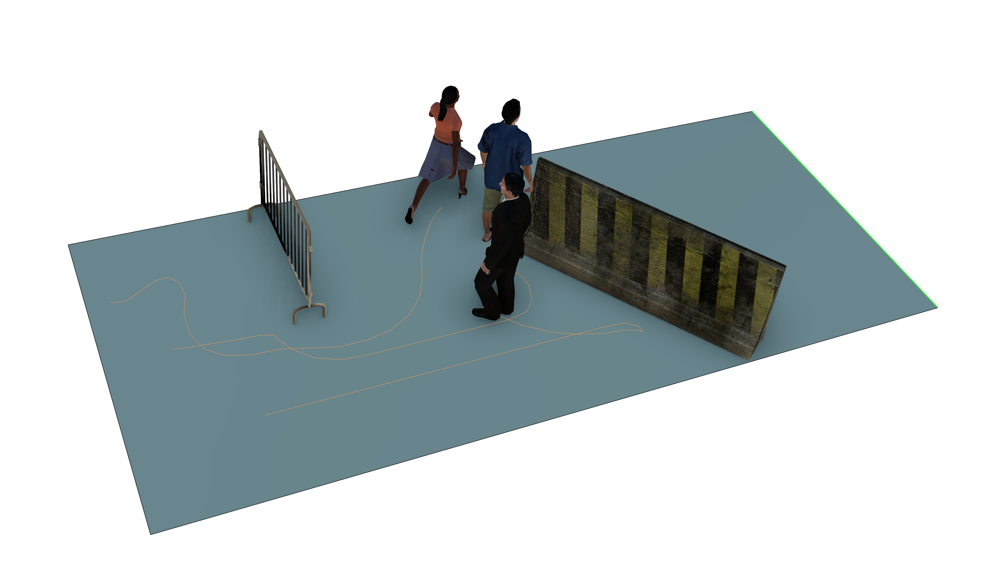
Pathfinder Obstacles are objects that represent dynamic changes in the environment that might cause occupants to slow down in a portion of a room or even re-route, depending on the severity and size of the obstacle. They are applied as patches on the navigation mesh that override the current speed modifier in the affected rooms (see Room Properties). Some uses of obstacles include, but are not limited to the following:
An environmental hazard, such as smoke or fire.
The following images show occupants waiting for one obstacle to be removed and then re-routing after another is introduced later.
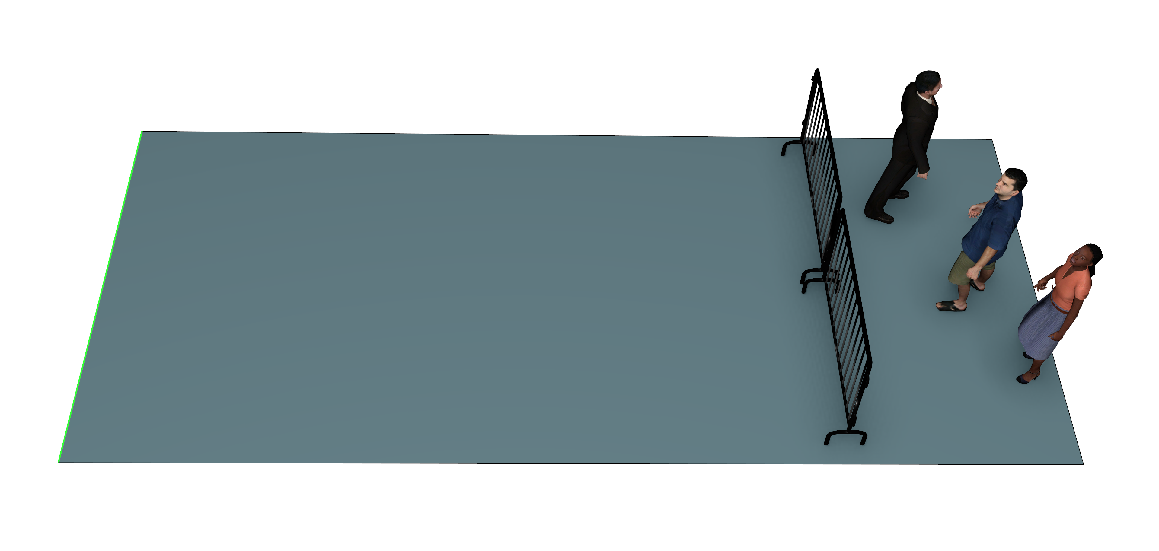 | 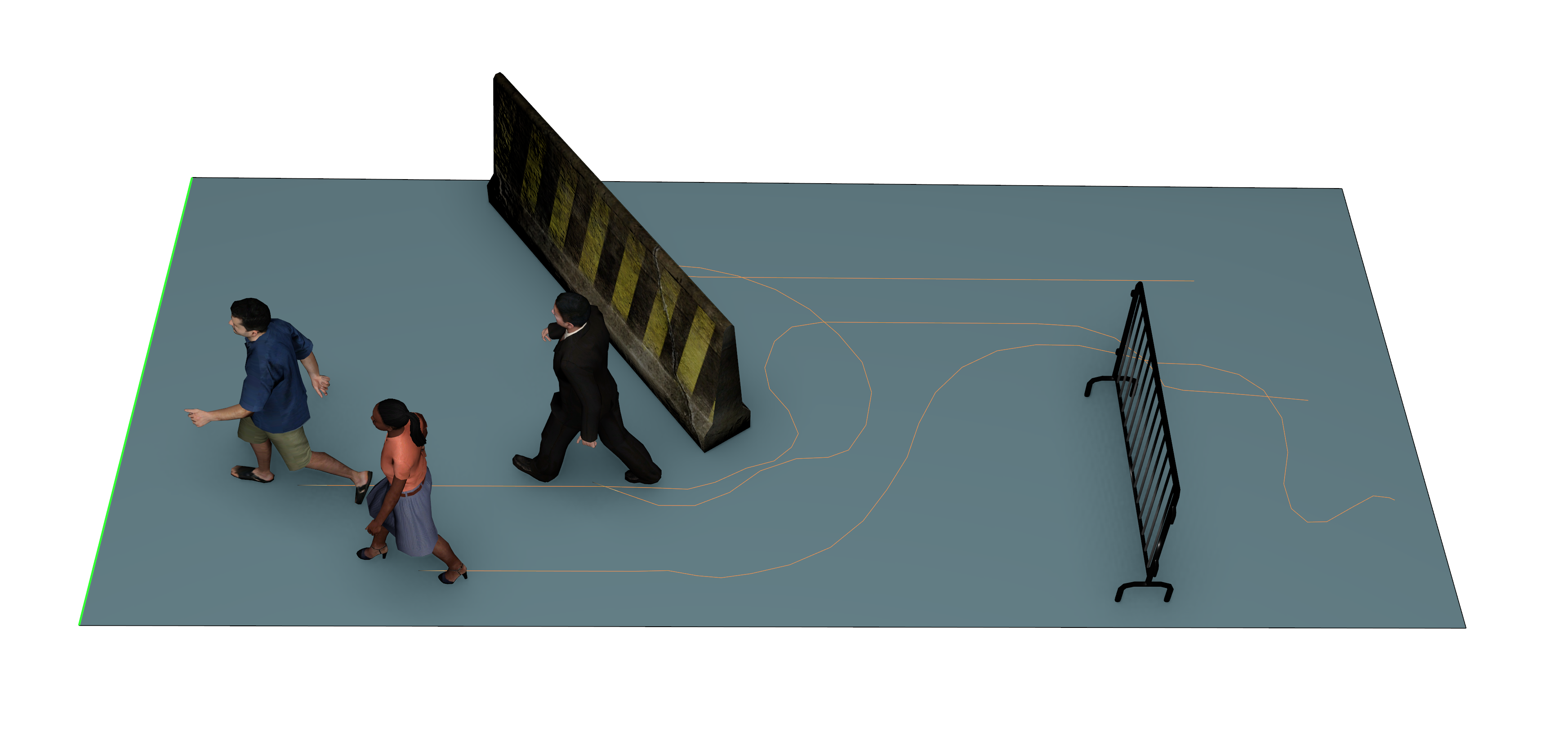 |
Obstacles can be created several ways, including by using the Obstacle drawing tool and by converting an imported CAD object into an obstacle.
To define the obstacle as an axis-aligned block using the Obstacle drawing tool, perform the following:
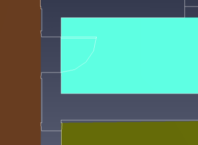
If the selected points lie in the same Z plane, the resulting obstacle will appear as a 3D box that extends slightly above and below the selected Z plane. This is the Search Volume of the obstacle. It is intersected with the navigation mesh to determine which portion of the mesh should be categorized as part of the obstacle. The intersection portion is represented as a solid white polygon, while the Search Volume is represented as a translucent box as shown in Figure 43.
An obstacle can also be drawn as a polygon. To do so, perform the following:
If the all the clicked points were on room faces that share the same plane, that plane is used as the basis for the Search Volume. The search volume appears as a prism, aligned with the plane and extending slightly above and below the plane as shown in Figure 44.
If the clicked points are in faces that lie in different planes, the resulting Search Volume prism is aligned with the plane that maximizes the resulting area of the polygon when the points are projected onto the plane. If the drawing tool selects the wrong plane, right-click the obstacle and select Align Obstacle with Plane, which opens the Set Normal dialog. The correct plane can then be entered into the dialog or can be clicked in the 2D or 3D view.
 |  |
Obstacles can also be created from imported CAD objects. This can be useful for visualizing the obstacle in a more realistic manner in Results and for automatically determining the Search Volume from the shape of the CAD geometry. See Figure 42 for examples of CAD obstacles.
To create an obstacle directly from an imported CAD object, perform the following:
The obstacles are then added to the Obstacles group in the Navigation View, with their group hierarchies mirroring that of the original imported CAD objects.
By default, the obstacles' Search Volumes will be linked to their CAD geometry as described in Obstacle Properties and are hidden from view. To view them, under the View menu, select Show Imported Obstacle Search Area. The images below show the search volumes hidden and visible. The area where the search volumes intersect the navigation mesh are always visible as long as the source obstacle is visible.
 |  |
CAD obstacles can also be created from existing obstacles. This might be useful if a custom Search Volume shape is desired that does not match the automatic volume chosen by linking it to the CAD geometry. It might also be useful if obstacles are created before the CAD objects are imported. To create a CAD obstacle in this manner, perform the following:
Imported.
The property panel will update with new available properties.To edit an obstacle’s properties, select the obstacle. Its properties will appear in the property panel as shown in Figure 47.

1, and its height varies from 0 m to 1.3 m proportional to the inverse of its current speed factor.
If using a speed limit, the obstacle is only visible if the limit was not set to disabled in Pathfinder, and the height is directly proportional to the speed limit divided by 1.2 m/s (see Figure 48).1.
See Figure 49 for an example.
See Converting imported CAD objects into obstacles or Assigning imported CAD geometry to an existing obstacle for more details on how to specify the CAD geometry.Imported.1.8 m below the Z plane of the lowest imported point.
The lower bound is chosen such that the obstacle’s imported geometry can be located above the navigation mesh and still affect the mesh below, such that the obstacle can be treated as an overhead obstruction.
This is similar to how obstruction subtraction works when generating navigation elements as discussed in Working with Imported Data.
By default, the search volume is hidden for linked CAD obstacles.
To show it, under the View menu, select Show Imported Obstacle Search Area.
See Figure 46 for an example showing the extended Search Volume..01 so the occupant can still eventually escape the obstacle.This works similarly to Speed Modifier except that it sets a maximum speed for the occupant rather than a factor.
 |  |
In Pathfinder, occupants cannot pass between two rooms unless they are joined by a door. Doors provide useful flow measurements in simulation results. Also, in the SFPE mode doors act as the primary flow control mechanism. You can add doors using the Add a New Door tool.
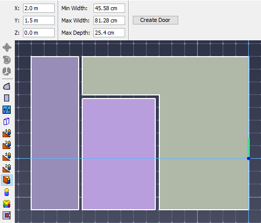
When adding doors, different parameters provide hints to Pathfinder for finding a valid door as shown in Figure 50.
Thin doors can be used to connect two rooms that touch one another as shown in Figure 51. A door is needed in this example to allow occupants to travel from one room to the other.
To create a door in this manner:
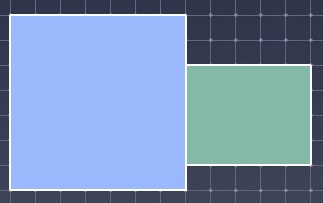 |  |
Thick doors are often useful in realistic models, especially when CAD geometry has been imported. In real scenarios, rooms will not touch each other by infinitely thin walls as shown in Figure 53.
To create a thick door to connect these rooms:
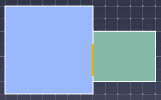
When simulating, thick doors have a special representation: the area of the door will be partitioned in two, and each half is attached to its touching room. A thin door is placed in the middle of the area to represent the thick door.
 |  |
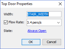
To edit a door’s properties, select the door. Its properties will appear in the property panel as shown in Figure 55.

Checking this box overrides the default door flow rate setting in the Simulation Parameters Dialog (see Parameters).
Setting this value controls the maximum occupant flow rate for the door in units of pers/s.
This can be used, for instance, when a particular door has been measured to flow at a specific rate and that rate must be reproduced.
A value of 0.9 pers/s, for instance, would mean that one occupant can go through the door every 1.1 seconds (1/0.9).
Amount of time for which each occupant must wait at the door before walking through it. This can be used to simulate turnstyles or doors with access keys. The specific wait time for each occupant will be drawn at random from a predefined continuous or discrete distribution.
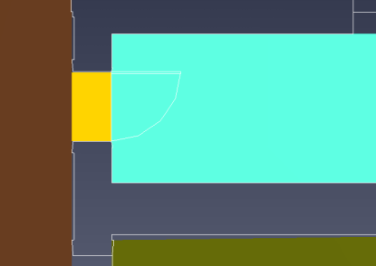
By default, all doors are always open throughout the simulation. To change this, click the link to the right of State.
The Edit Door State dialog will appear as shown in Figure 56. This dialog allows the initial state of the door to be specified as well as additional timed states.
As shown in the figure, for example, the door is initially open, closes at t=10 s, opens in +X direction at t=20 s, and then opens in both directions again at t=30 s.
Even though a door can only be travelled through in two possible directions, the drop-down box allows +X, -X, +Y, and -Y. When one of these directions is chosen, the actual direction Pathfinder chooses is the closest along the door’s normal.
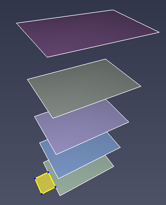
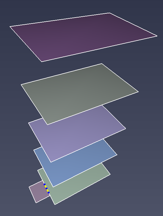
Stairs in Pathfinder are represented by one straight-run of steps. They can be created with two tools. One tool allows creation of stairs between two semi-parallel boundaries of rooms, and the other allows creation of stairs that extend from one room boundary until a criterion is met, such as number of steps, height of stairs, etc., or until another room is reached.
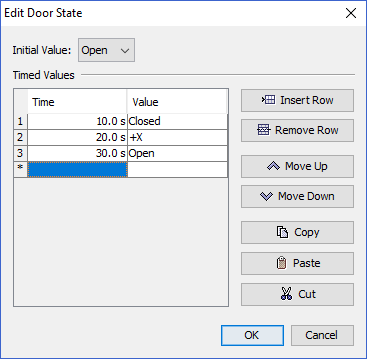
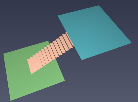
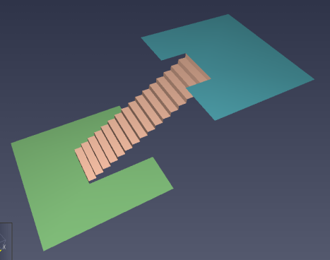
One requirement of all stairs for successful simulation is that each end of the stairs must connect to boundary edges of the rooms, meaning that there must be empty space at the top of the stairway and empty space below the bottom. See Stair geometry requirements for an illustration of this issue. The size of the gap must be greater than or equal to the radius of the largest occupant to travel on the stairs.
 |  |
One way to create stairs is to draw them between two pre-existing rooms. Stairs of this type will match the ends of the stairs exactly to the edges that they were drawn between, which means that the tread rise and run may or may not match the actual slope of the stairs. In Pathfinder, the speed on stairs is determined by the specified tread and run. The geometric slope of stairs is for display only and not used to calculate the speeds.
To create stairs between edges:
To change the display, you may:
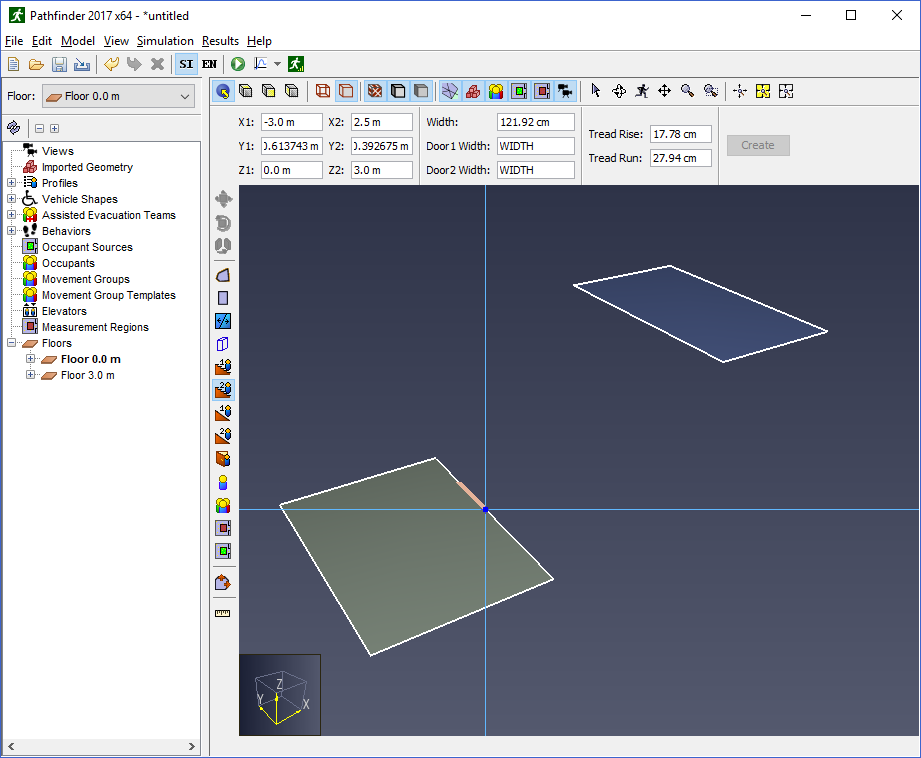 |  |
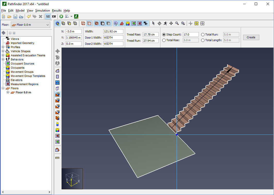
Another way to create stairs is to have them extend from an edge and exactly match the specified tread rise and run. They will stop when they meet a specified criterion or reach another room.
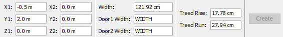
The property panel for the one-click stair tool, as shown in Figure 62, provides four ways to terminate the stairs:

To create stairs in this manner:
After creating stairs in this manner, the Z location of the next floor or room will have to match the top of the stairs exactly for the next room to connect properly to the stairs. This can be done by clicking the top of the stairs in the 3D or 2D view when choosing the Z location for either the floor or next room.
After creating a one-click stair, you can only modify the stair by clicking the handles and dragging to existing geometry.
Stairs have a number of properties that control their geometry and behavior of occupants that travel on them. When a stair is selected, these properties can be seen in the stair’s property panel as shown in Figure 64.

In areas on the navigation mesh that have not been defined as stairs or ramps, during the simulation Pathfinder attempts to identify when occupants are traveling over stair-like geometry and model their movement as though they are moving over stairs. In these situations where stairs have been inferred from the geometry, occupants will move slower based on the same speed fraction used for user-defined stairs and calculate distance traveled as though they are moving on a diagonal.
Inferred stairs commonly come from user-defined stairs that have been merged with surrounding geometry or from uneven geometry that has been joined using vertical floor or stair elements. Because Pathfinder agents' positions are confined to the navigation mesh, using such geometry as-is can introduce inaccuracies in speed and distance related to the diagonal nature of movement on stairs.
This feature is enabled by default and will operate without creating any specific modeling element. Inferred stairs can be disabled in the following two ways:
PTH_STAIR_INFERENCE_ENABLE and set the value to false then restart Pathfinder, or-J-Dstair_inference_enable=falseIn most cases where the two are interchangeable, user-defined stair objects and inferred stairs produce very similar simulation results. Using one or the other may be more useful when creating a specific model element based on the situation. The following table offers a comparison between the two approaches to help clarify when one approach or the other might be more helpful.
| Characteristic | User-defined Stairs | Inferred Stairs |
|---|---|---|
| Control | Specify the intended tread height and depth independent of geometry as well as one-way options for escalators and moving walkways. | Slope is automatically determined by the raw simulation geometry and direction constraints are not supported. |
| Limitations | Top and bottom entry only. | No specific geometry limitations and stadium-style side entry steps are possible. |
| Simulator Performance | Slightly faster for occupants on the stair component because maximum velocity does not need to be calculated. | Slightly slower for occupants in the area of the inferred stair because maximum velocity must be calculated by analyzing the navigation mesh. |
Additional information is available in the Pathfinder Technical Reference (Pathfinder Technical Reference, n.d.).
Ramps are nearly identical to stairs in how they are created and represented. Like stairs, they have two implicit doors at either end and always take the shape of a rectangular piece of geometry.
They also have very similar creation tools: the two-point ramp tool ![]() , and the one-point ramp tool
, and the one-point ramp tool ![]() .
The key difference between ramps and stairs is that ramps do not affect the speed at which occupants travel by default.
.
The key difference between ramps and stairs is that ramps do not affect the speed at which occupants travel by default.
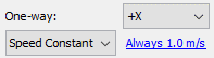
Pathfinder provides some limited support for escalators. They are essentially stairs with slightly modified properties.
To create an escalator, perform the following:
In the results view, escalators do not appear differently than stairs.
By default, occupants do not walk on moving walkways or escalators, and they will not stand on any specific side. This can be changed by modifying the occupant’s profile and selecting their Escalator Preference (see Profiles). If an occupant is walking, the escalator’s speed constant will be added to the occupant’s current speed on the escalator.
Pathfinder also provides limited support for moving walkways. This is similar to creating escalators, but instead of setting a speed constant on an existing stair, the speed constant is set on a Ramp instead, which can be made flat like a walkway.
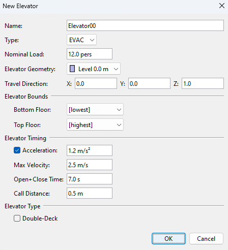
Pathfinder offers two different types of elevators, EVAC and SCAN. The two types differ in the order in which they decide to service levels and discharge occupants.
EVAC elevators are intended to model egress-mode operation, which is based on current thinking described in Using Elevators In Fires (Bukowski and Li 2010).
The basic operation of elevators in evacuations can be summarized as follows:
SCAN elevators are intended to model general-purpose elevator use. The basic operation of SCAN elevators can be summarized as follows:
The elevator will wait until it is called to service a floor. As soon as it is called, it will begin moving in the direction that it has been called from.
While the Elevator is moving, it will continue to travel in that direction as long as it has serviceable floors. Serviceable floors while the elevator is moving are:
Once the elevator no longer has any serviceable floors in the current direction, it will look for the furthest elevator call regardless of the direction it was called to travel in. It will first prioritize the furthest call in the same direction last traveled. If no call exists, it then will move to the furthest call in the opposite direction last traveled.
This behavior is intended to scan or sweep the elevator floors from end to end, giving relatively equal priority to each floor that the elevator is called to. Once there are no active service calls, the elevator will wait until called again.
Elevators can be made after creating the rest of the model.
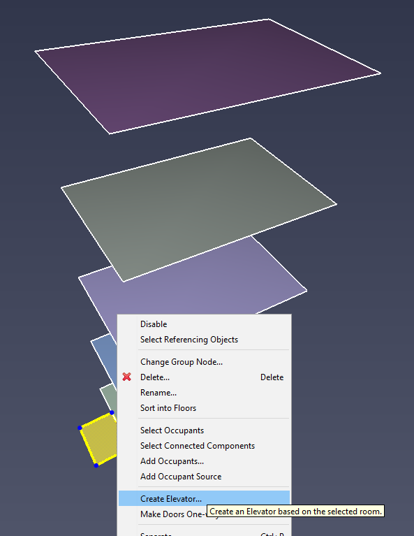
Perform the following steps to create the elevator (refer to Figure 20):
If necessary, Pathfinder will automatically subtract holes in existing geometry to make space for the elevator shaft. It will also delete existing rooms, doors, stairs, and ramps in the elevator shaft. Pathfinder will ask before making any of these changes.
In order for occupants to use elevators, they must either be allowed to use elevators in their Profile under Restricted Components (see Movement Tab) or be explicitly told to do so through their behaviors, as discussed in Behaviors. Occupants can be encouraged to prefer elevators to stairs using the Elevator Wait Time Profile parameter (see Door Choice Tab).
 |  |  |
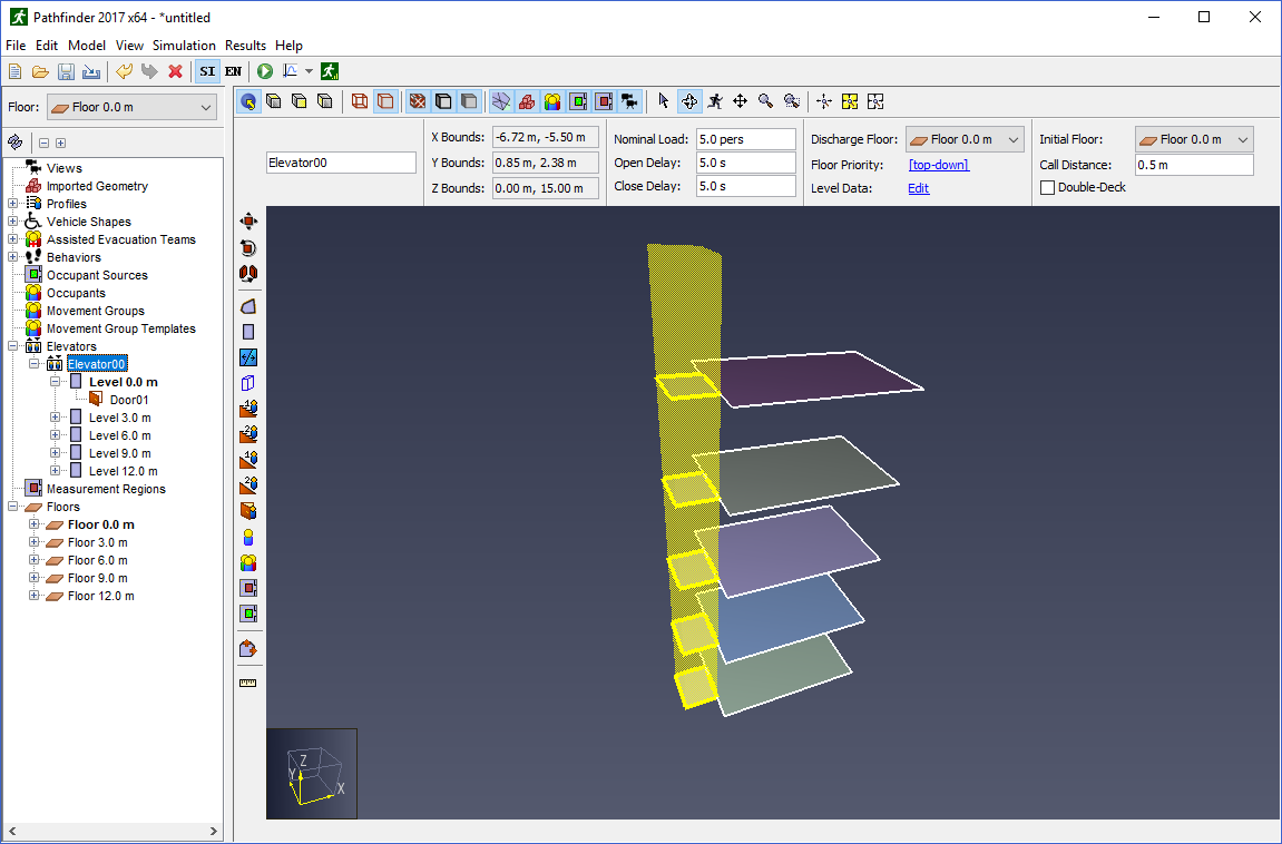
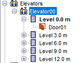
Once an elevator is created, it will appear in the model as a series of "rooms" and doors connected by a transparent elevator shaft as shown in Figure 71. There is one room and set of doors for each floor to which the elevator can connect. In the 3D and 2D Views, each room is shaped the same as the base room that created the elevator. In the Navigation View, each room is shown under the elevator rather than the Floors top node, see Figure 72. In addition, each set of doors for the room is shown under the room. By default, each of the rooms is named after the floor on which it connects. If the elevator is disconnected completely from a floor as discussed in Connecting/Disconnecting floors, the room is named "<Disconnected Level>".
 |  |
Once an elevator is created, the elevator’s properties can be edited by first selecting it from the navigation view or by ALT-clicking one of its rooms from the 2D or 3D view. Its properties can be edited in the property panel as shown in Figure 73.

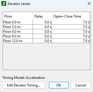
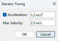
By selecting the Edit Elevator Timing… option at the bottom of the dialog, an Elevator Timing dialog will open as shown in , allowing you to modify the speed of the elevator moving between floors.
The timing options shown are the same as those shown when creating the elevator. Initial Floor:: The floor at which the elevator deck will be located at the beginning of the simulation. Call Distance:: The distance away from the elevator door at which an occupant can call the elevator. Double-Deck:: Whether the elevator should use two connected decks to transport occupants. Please see Double-Deck Elevators for details.
The nominal load is an estimate of the number of people that represent a full elevator load. The default value is based on an estimate of how many occupants of default size (diameter = 45.58 cm) would normally fill the elevator in steering mode. Increasing or decreasing the nominal load will cause occupants' sizes to be scaled up or down while they are on the elevator.
The scale factor (default: 1.0) is determined by a correlation to the density produced by the nominal load. This makes it possible to adjust loading while still accounting for differences in individual occupants' size.
In steering mode, the geometry of the elevator can lead to reduced loads (e.g. if the elevator is 2.8 persons wide). Please verify that the resulting (post-simulation) elevator loads match elevator manufacturer recommendations.
When an elevator is created, by default it is connected to every floor its doors touch along the elevator shaft. Individual elevator doors can be disabled, however, to prevent entering/exiting the elevator through those doors on specific floors.
To do so:
To re-enable it, right-click the door from the Navigation View and select Enable.
Alternatively, right-click an elevator level and select Disable to disconnect all the elevator’s doors on that level, effectively preventing the elevator from picking up occupants on that level.
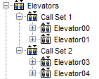
By default, each elevator is called individually. Elevators can be grouped into call sets, however, so that when one is called, all elevators in the call set respond and travel to the pickup level.
To create a call set:
All elevators in the group will be in the same call set as shown in Figure 77.
Double-deck elevators use two connected decks to transport occupants, which increases the efficiency of moving occupants between floors. Occupants use a double-deck elevator similarly to a regular elevator.
After calling an elevator, the double-deck elevator arrives at the given floor, and the doors of its two decks open at the two adjacent floors (even and odd). When the decks are loaded, the double-deck elevator moves to either pickup or discharge at another set of floors.
Occupants traveling in a double-deck elevator can only discharge on a floor with the same parity that they entered from. Occupants that entered on the lower (even) deck will only be able to discharge on even-numbered elevator levels. Occupants that entered on the upper (odd) deck will only be able to discharge on odd-numbered elevator levels. If no such level exists, the occupants could become stuck if using the explicit Goto Elevators Action, and otherwise they will choose not to use the elevator while pathfinding.
After arriving at a floor to discharge, the elevator doors of both decks open, allowing occupants to leave both decks of the elevator.
There are several conditions that must be followed when using a double-deck elevator in Pathfinder:
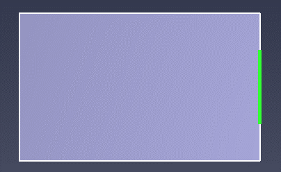
In Pathfinder, exits are merely thin doors that exist on the boundary of the model. An exit can only have a room on one of its sides.
Exits are created in almost the same way as thin doors as discussed in the section, Thin doors. The only difference is that the door must lie on an edge of a room, and the edge must not be shared between two rooms.
Exit doors are displayed the same as thin doors except that they are green as shown in Figure 78.
All selections and model edits can be undone and redone using the Undo (![]() ) and Redo (
) and Redo (![]() ) buttons, as well as the shortcuts Ctrl+Z and Ctrl+Y, respectively.
The shortcuts Ctrl+Shift+Z and Ctrl+Shift+Y will skip selection history and revert or continue to the next model edit.
) buttons, as well as the shortcuts Ctrl+Z and Ctrl+Y, respectively.
The shortcuts Ctrl+Shift+Z and Ctrl+Shift+Y will skip selection history and revert or continue to the next model edit.
Alternately, the drop-down tab adjacent to the Undo (![]() ) and Redo (
) and Redo (![]() ) buttons or the Edit→Undo and Edit→Redo menu can be used to view your Undo or Redo history and jump to a specific point.
) buttons or the Edit→Undo and Edit→Redo menu can be used to view your Undo or Redo history and jump to a specific point.
The size of your history can be changed in File→Preferences→Undo/Redo History. History for model edits is limited by that preference, while history for selection-only changes has double that limit.
Pathfinder can import a large number of image and CAD formats. Imported files can be used as an aid to more quickly generate the navigation mesh and give more context and visual appeal to a simulation.
Background images can be imported by clicking New Background Image on the Model menu.
(0,0,0) in the model.(1,0,0).
As shown in the figure, the A→B vector should be 90 degrees from the X axis.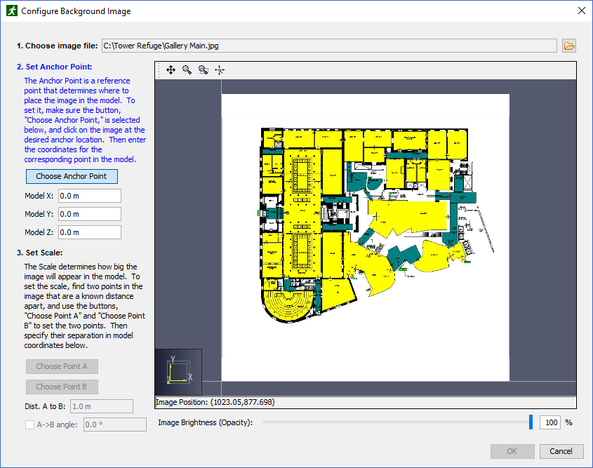
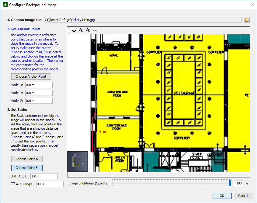
The imported image is added to the Imported Geometry → Background Image group in the Navigation View. The image can be edited and deleted from there.
Pathfinder can import geometry from several CAD formats, including buildingSMART’s IFC format for building information models (BIM), AutoCAD’s DXF (Drawing Exchange Format), DWG, FBX, DAE, OBJ, and glTF/GLB (Graphics Language Transmission Format) files.
Depending on which type of file is imported, Pathfinder also provides various tools to generate the navigation mesh elements such as rooms, doors, and stairs, see Working with Imported Data.
To import one of these files:
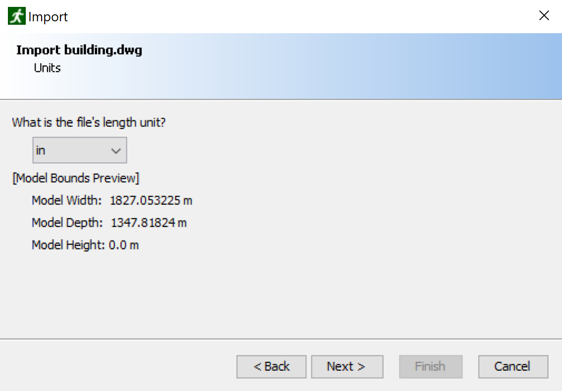 |  |
Unknown.
This selection controls the default settings in the subsequent prompts.
In some cases, Pathfinder is able to detect whether the file was exported using a SimLab plugin and will select this option automatically.+Y is down.Specular (Basic) workflow, as this is the only workflow currently supported by IFC and FBX files.
In some cases, however, such as when an FBX file is exported from Unreal Engine, the PBR parameters are packed into the basic specular texture property.
In this case, the following two options can be used to reinterpret the basic specular workflow as a PBR workflow for correct lighting.Metallic (PBR) workflow, even if they are specified in the import file using the Specular (Basic) workflow.
When using this option, the PBR parameters can either be set to constant values or can be reinterpreted from other non-PBR color properties.
For instance, when an FBX file is exported from other software, for each material it might create a single image containing the Metallic, Roughness, and Ambient Occlusion parameters, stored in the red, green, and blue color components, respectively.
It then might set the specular texture in the FBX file to this combined image.
When an exporter does this, there should be accompanying documentation with the FBX file that indicates how these PBR parameters are stored in the FBX file.
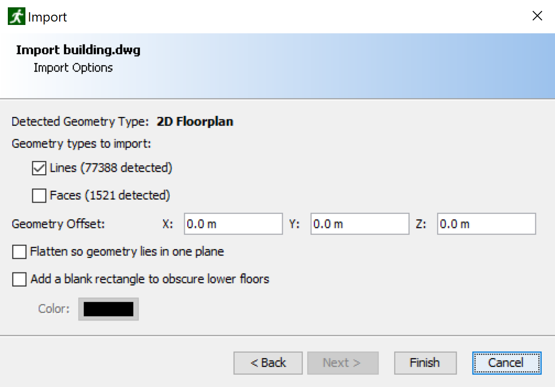
When importing the FBX file in the above example, in the import dialog, the Metallic, Roughness, and Ambient Occlusion properties should all be set to From Specular, and the color components should be set to R, G, and B, respectively (see Materials).<ignored> by default so it does not contribute to generating the model as described in Working with Imported Data, (default=checked only for 2D floorplans.)All imported elements will be added to the "Imported Geometry" node in the Navigation View. If the CAD file was a DWG or DXF, the grouping structure will include the model level, the layer level, and all entities distributed within the layer. For IFC files, the grouping is determined by the Object Grouping setting as specified above. For other CAD files, the grouping structure will match the node structure in the file. If both lines and faces were included in the import and an entity contained both lines and faces in the CAD file, the entity is split into two in Pathfinder - one with the lines, and one with the faces.
When a CAD file is imported, there may be many resulting objects. Depending on the type of imported file, there are various levels of information that may be imported for each resulting object. Each object has a name and always includes some geometric information, such as the 2D curves or 3D faces composing the object. For some files, such as IFC files, there may be even higher-level information such as whether the object is a door and the door’s width. Pathfinder uses this information to generate model elements as described in Working with Imported Data.
Common to all import objects is the ability to set some visual properties, such as color and opacity for each component of the geometry. The imported geometry is sent as-is to 3D Results, resulting in a clean and fast graphical representation of the data.
When an imported object is selected, its property panel appears as shown in Figure 84.

Imported objects have the following properties:
IfcRoof.
This value cannot be changed.IFC files provide building information model (BIM) data in a fully 3D format. This format contains advanced data about the types of objects in the building, including slabs, stairs, doors, etc., and it provides the smoothest workflow for converting imported objects into Pathfinder elements (see Generate Model from BIM). It is also supported as an export format for many architectural CAD packages, including Revit.
When exporting an IFC file from another CAD package, such as Revit, it is preferable to use the IFC 2x3 Coordination View, though other IFC views should work as well.
Each object imported from an IFC file corresponds with an IFC Entity instance. Currently, only instances with 3D geometry are imported. In addition, openings (holes) are pre-subtracted from objects, and the openings are not imported as objects. For example, a wall in the IFC file might be associated with an opening object for a window. When importing, Pathfinder will subtract the opening’s geometry from the wall geometry and only import the resulting wall. The window would additionally be imported as a separate object.
The Object Type for each object is set to the object’s IFC Entity type, such as IfcWall. The Import Type is chosen automatically based on the object’s Object Type and possibly other properties specified in the IFC file. For instance, an IFC object with entity type, IfcCovering has an associated PredefinedType property that specifies what kind of covering it is, such as a wall covering or floor covering. For floor coverings, Pathfinder will automatically set the object’s Import Type to Floor during import. Other types of coverings become Obstruction.
Table 5 specifies how the Import Type is chosen for imported IFC objects:
| IFC Entity Type | IFC Predefined Type | Object Name | Import Type |
|---|---|---|---|
IfcBuildingElementProxy | "Path of Travel" "RPC Male" "RPC Female" | <ignored> | |
IfcCovering | FLOORING | Floor | |
IfcDoor | Door | ||
IfcElement | Obstruction | ||
IfcRamp | Floor | ||
IfcSlab | Floor | ||
IfcStair | Stair | ||
IfcTransportElement | ESCALATOR | Stair | |
IfcTransportElement | MOVINGWALKWAY | Floor | |
IfcSpace | Room | ||
IfcBuilding | Building | ||
| <all others> | <ignored> |
The IFC Entity Type includes derived entities unless specifically listed in the table.
For instance, IfcElement includes IfcBeam, IfcColumn, etc., since those entities derive from IfcElement and are not listed in the table.
IfcElement does not, however, include IfcDoor since IfcDoor is in the table.
In addition, IfcDoor includes both IfcDoor and IfcDoorStandardCase since IfcDoorStandardCase is derived but not listed.
DXF is a basic CAD format provided by Autodesk. This format supports basic geometry types, including 3D faces, lines, and text, but it does not support material information, such as textures, lighting parameters, etc.
Import Type for all DXF objects is Obstruction.
In order for the Import Type to be more useful, it must be set manually.
Some suggestions for doing so are given in Generate Model from BIM.
The DWG format is similar to DXF, but it also has basic support for materials, including textures. It has only basic support for mapping textures onto objects, however, and few CAD applications can export DWG files. Some, such as Revit, exclude material and texture information (see more information in Importing Revit Files below).
Import Type for all DWG objects is Obstruction.
In order for the Import Type to be more useful, it must be set manually.
Some suggestions for doing so are given in Generate Model from BIM.
FBX provides support for 3D faces only, but it has good support for material information and materials mapping. In addition, many 3D modeling applications have native support for exporting FBX files.
Import Type for all FBX objects is Obstruction.
In order for the Import Type to be more useful, it must be set manually.
Some suggestions for doing so are given in Generate Model from BIM.
Pathfinder also supports importing glTF 2.0 files (and the GLB variant).
Like FBX files, glTF is a 3D interchange format with good support for materials and material mapping and is most commonly used to specify 3D faces, though it has some limited support for lines.
glTF files can also include skinning information, which makes it useful for importing custom avatars as well (see Importing Custom Avatars).
Unlike FBX files, glTF files have native support for physically-based materials (PBR), which can significantly improve the appearance of imported geometry, especially when combined with image-based lighting in Results. In addition, glTF is a newer format than FBX and is not natively supported for export by as many 3D modeling applications; however, external export plugins are available for many of these applications.
glTF files come in two flavors:
The following glTF extensions are also supported:
Import Type for all glTF objects is Obstruction.
In order for the Import Type to be more useful, it must be set manually.
Some suggestions for doing so are given in Generate Model from BIM.
PyroSim and FDS files provide objects with 3D faces. If the imported file contains holes, the holes will be automatically subtracted from the solid obstructions and discarded. If the file contains grids, the grids will be intersected with each other as FDS would, and the remaining faces of the grids will be imported. If the file contains OPEN vents, the vents will be subtracted from the appropriate grid faces and discarded.
Import Type for all PyroSim and FDS objects is Obstruction.
In order for the Import Type to be more useful, it must be set manually.
Some suggestions for doing so are given in Generate Model from BIM.
While Pathfinder cannot directly import Autodesk Revit files (RVT), there are several ways to export the data from Revit into a file format that Pathfinder can read. Each method has advantages and disadvantages as discussed below.
This method requires the use of a third party plugin, but it generally produces good results with materials, textures, and texture coordinates well-supported. In many cases, this is the most reliable method of reproducing the graphical representation of the original Revit file within Pathfinder. SimLab Soft is one company that provides commercial FBX export plugins for several CAD packages, including Revit and Sketchup, among others, and provides robust texture support.
To export using a third-party plugin, perform the following:
C:\ProgramData\Autodesk\Revit\Addins\SimLab\FBXExporter\data\Imported_Textures\#
where # is a number specific to the exported file, such as 40.The first method exports a building information model (BIM) in the industry foundation classes (IFC) format (see Importing IFC Files).
To perform the export in Revit 2019, perform the following:
This method exports a DWG file directly from Revit, which can then be imported into Pathfinder. While simple to perform and only requires Revit, this method loses all information about materials, including textures, due to Revit’s limited DWG support.
To perform the export in Revit Architecture 2014, perform the following:
This method exports an FBX file directly from Revit, which can then be imported into Pathfinder. As with exporting a DWG, this method is simple to perform and only requires Revit. Unfortunately, this method also loses all information about materials and textures because Revit encrypts the material data, making it unreadable by Pathfinder.
To export using Revit Architecture 2014, perform the following:
This method requires both Revit and AutoCAD and does not perform a perfect conversion, but it retains some information about materials and texture coordinates.
The steps described here use Revit Architecture 2014 and AutoCAD 2014:
The following are recommended settings for the FBX import:
See Importing from a CSV File for more information.
Each type of file that can be imported provides an aid for creating navigation geometry. The different types can be worked with in various ways to create the desired rooms, stairs, and doors.
The easiest way to create a complete Pathfinder navigation mesh, including rooms, doors, and stairs, is to use the Generate Model from BIM action. This action works best with imported IFC files, but it can work with other CAD file types as well, as long as those files contain 3D face data, such as from DXF, DWG, FBX, and GLB/glTF files. These non-IFC file types require some extra steps as outlined below.
To use this action, perform the following steps:
Obstruction, so this only needs to be done for non-Obstruction objects.Door43, use the search tool (Edit→Find) to select all with the text Door in the name.
Then set the Import Type to Door on the whole selection.<ignored>.
This may be necessary, for instance, if the file contained stand-in objects, such as the building envelope.If only a subset of the imported objects needs to be modeled in Pathfinder, either set the Import Type for unnecessary objects to <ignored> before generating the model with the above steps or perform the following instead:
Obstruction, as obstructions are automatically subtracted during model generation.The following table describes how Pathfinder converts imported objects into Pathfinder navigation elements based on their Import Type and any additional properties that may have been imported along with the object:
| Import Type | Pathfinder Type | Details |
|---|---|---|
| <ignored> | – | These objects are completely ignored when generating the model. |
| Door | Door | To generate a Pathfinder door, Pathfinder first obtains the geometry of the imported door that will define the shape of the Pathfinder door. If the imported door has an associated wall opening, the wall opening’s geometry is used. If not, the door’s geometry is used. The minimum bounding rectangle of the geometry is then used to define the Pathfinder door shape. If the door’s geometry was used and the door has an associated opening width property, the resulting door will be no wider than this opening width. The minimum bounding rectangle is then extruded into a box such that the bottom of the box is slightly below the bottom of the source geometry and the top is slightly above the top of the source geometry. This box is then subtracted from the generated rooms, and a Pathfinder door is used to fill the gap. |
| Escalator | Stair and Room | The conversion is performed the same as for Import Type Stair. If the resulting stair must be treated as an actual escalator, its properties must be set after generating the model (see Escalators). |
| Floor | Room | Pathfinder will identify the potential walking surfaces of the imported objects.
It will then identify all potential obstructions and subtract them from the walking surfaces.
NOTE: With the exception of objects with Import Type, Door and |
| Moving Walkway | Room | The conversion is performed the same as for Import Type Floor. If an actual moving walkway is needed instead of a room, delete the generated room and create a moving walkway as described in Moving Walkways. |
| Obstruction | – | These objects do not directly become Pathfinder objects. Instead they become either holes in the rooms or thin boundary walls. |
| Ramp | Room | The conversion is performed the same as for Import Type Floor. If an actual ramp is needed instead of a room, delete the generated room and create a ramp instead as described in Ramps. |
| Stair | Stair and Room | To generate a Pathfinder stair, the imported object’s steps are first generated as if they were rooms. Like with rooms, overhead obstructions, such as railings, are subtracted from them. After this, the steps of the stair are connected together using Pathfinder stairs. If multiple steps can be strung together in a row and have similar rise and run characteristics, they all become one stair. Otherwise, they are separated into multiple stairs so that each stair has similar rise/run to the underlying imported geometry. This process may leave part of the stair geometry, such as the landings, as rooms. |
| Room | Room | The conversion is performed similarly to Import Type Floor. However, Pathfinder will seek to use only the bottom of the geometry as a walking surface. Rooms may also have custom parameters to set occupancy and generate occupants; these are exported by the Evac4Bim Plugin for Revit (https://github.com/YakNazim/Evac4Bim/releases). |
| Building | – | These objects do not directly become Pathfinder objects. Instead they provide additional information to create new occupant profiles and provide an initial delay for generated behaviors. These parameters are only exported by the Evac4Bim Plugin for Revit (https://github.com/YakNazim/Evac4Bim/releases). |
When using the Generate Model from BIM action, various settings can be specified in the Generate Settings dialog as shown in Figure 85.
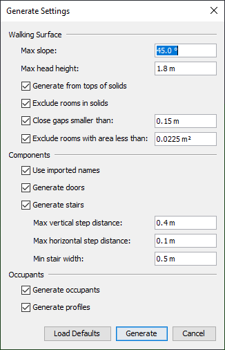
The following settings are available in the Generate Settings dialog:
If checked, adds Pathfinder doors to the navigation mesh from the imported doors.
If checked, adds Pathfinder stairs to the navigation mesh from the imported stairs.
The following settings will only impact the handling of objects exported by the Evac4Bim Plugin for Revit (https://github.com/YakNazim/Evac4Bim/releases):
Default profile is used.
If the Default profile has been deleted, the first existing profile in the model is used.
The resulting occupants will also be assigned to a new Behavior that has a single Goto Any Exit action (see The Goto Exits Action).
If there are any objects with Import Type Building, the behavior’s Initial Delay is set to the distribution defined in the building.While the Generate Model from BIM action can quickly provide a good starting point for a Pathfinder simulation, it does have some limitations, including:
Stair.
Some objects, such as steps in a stadium might look like stairs but are actually marked as floors.
In this case, stairs will not be automatically generated, and will look like small, disconnected rooms instead.IfcBuildingElementProxy.
This type is merely a stand-in data type for objects not inherently supported by the IFC standard.
They may or may not be physical objects in the model, and there is currently no way to differentiate, so Pathfinder treats them all as obstructions.Depending on the imported CAD data, some problems may arise when generating the Pathfinder model. Table 7 below may help determine the source of the problem and resolve it.
| Problem | Cause | Solution |
|---|---|---|
| There is a wall in the middle of a generated room where there was no obstruction or there is a gap between rooms when they should be connected. | The wall/gap might actually be a very thin gap that exists between adjacent imported slabs. Pathfinder does not currently close these small gaps automatically. | Either draw a door along the edge that bridges the gap or adjust the geometry of the rooms and merge them together. |
| A generated door should connect two rooms but is an exit instead. | This can happen if the imported door had no associated wall opening, the door’s geometry was thinner than the surrounding wall, and there is no slab or other floor object under the door. | Select the door and use the manipulation tool to connect the door to the other side of the door opening. |
| A generated door appeared where it wasn’t expected. | This may happen if a single door was broken into several pieces and/or objects were marked as doors that weren’t actually doors. For instance, this might happen if the door trim is modeled as a separate object than the actual door, and the trim is also marked as a door. In this case, the piece of trim is modeled as a separate door. | Delete the door and draw manually instead. |
| A generated door was too small. | This is usually caused by the same problem as above. | Select the door and change the Width in the property panel to the desired size or delete and redraw the door if this does not work properly. |
| A generated door was too wide. | This can happen due to limitations in the door extraction algorithm, see Limitations. | Select the door and change the Width in the property panel to the desired size. |
| A door is missing | The imported object’s Import Type was not set to Door, or the door had no walking surface under it, did not have an associated wall opening, and was thinner than the surrounding wall.
This might also happen if there is a door threshold. | Draw the door manually. |
| A room is missing | This may either be because the imported object defining the floor did not have its Import Type set to Floor or the Exclude rooms in solids option was enabled and there is a solid object in the model marked as an obstruction that should not be in the model, such as one representing the building envelope. | Undo the import, ensure the imported object’s Import Type is set to Floor, and delete any objects that should not be in the model.
Then try generating the model again.
If this still does not work, draw the room manually. |
| A stair is missing | The imported stair object was not marked as a Stair or the step distances exceeded the limits set in the generate settings. | Undo the import, set the Import Type to Stair, and then perform the Generate Model from BIM action again, or draw the stair manually. |
| An imported stair was broken into several Pathfinder stairs. | This can happen if an imported stair does not conform to a Pathfinder stair, such as with spiral stairs. This might also happen if there are multiple directions from which an occupant could step down off a step of the stair. Another cause could be that the step rise/run changed drastically from one step to another, such as if the top or bottom step does not align exactly with the connecting slabs. | If the stair should have been generated as a single Pathfinder stair, delete the generated stairs and draw the stair manually. |
| The steps of the generated stair do not match the steps of the imported stair exactly. | This can happen if the steps of the imported stair do not have a consistent step height or tread depth or the imported stair did not line up exactly with the slabs it was connecting. In this case, Pathfinder averages the rise/run of the resulting steps over the entire rise/run of the stair, which may cause the steps to be slightly out of alignment with the imported stair. | If desired, select the Pathfinder stair and change its step rise/run in the property panel. |
| An elevator is missing. | Generating elevators is not currently supported. | Create the elevator manually, see Elevators. |
| An escalator has extra steps off of the side. | Escalators are generated as stairs. Pathfinder generates stairs using a generic algorithm where any flat surface can be treated as a step. If some of the geometry looks like it might be a step, Pathfinder will create a stair going to it. | Delete the extra stairs. |
While automatic model generation should work for most 3D CAD files, it may not always produce the desired result, the user might want more control over the rooms that are generated, or it might just be too prohibitive to set the Import Type for some non-IFC CAD files.
Pathfinder provides an Extract Room tool ![]() that can address these issues.
This tool allows rooms to be extracted individually using a flood-fill algorithm.
While it may take more effort to extract all the necessary rooms, it does not require objects to have an Import Type specified unless an object is to be ignored.
that can address these issues.
This tool allows rooms to be extracted individually using a flood-fill algorithm.
While it may take more effort to extract all the necessary rooms, it does not require objects to have an Import Type specified unless an object is to be ignored.
To use the Extract Room tool:
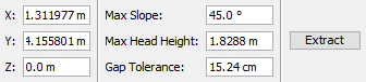
Below is an example of a 3D CAD model Figure 87 and a room extracted from it Figure 88.
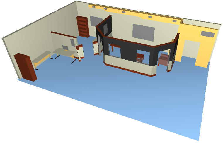 | 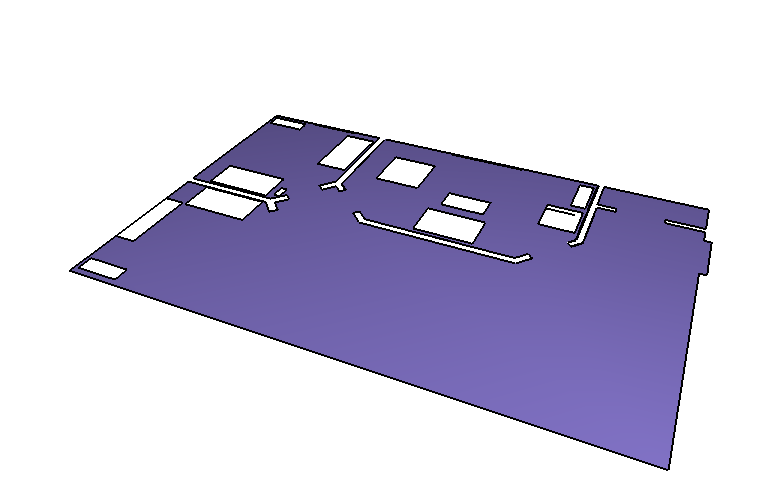 |
When using the extract room tool, Pathfinder will include all imported geometry with faces, even if hidden.
If an object must be excluded from room extraction, the object’s Import Type must be set to <ignored> before performing extraction.
Otherwise, this tool completely ignores the Import Type of the objects.
2D CAD data can be worked with in two ways:
To sketch the rooms using the built in drawing tools, refer to Rooms.
Extracting rooms from 2D CAD data works similarly to extracting rooms from 3D CAD data.
As in 3D extraction, the Extract Room tool ![]() is used.
In addition, the user must click a point in the model with the tool, and one room will be extracted.
is used.
In addition, the user must click a point in the model with the tool, and one room will be extracted.
The main difference from 3D extraction is that the clicked point must not lie on any 3D imported faces marked for room extraction; instead it must be in empty space (or on the background rectangle imported with a 2D floorplan). The clicked point should also be surrounded by imported 2D lines. These lines will form the boundary of the resulting room. For this reason, any lines that do not contribute to the room’s boundary, such as notations, symbols, etc. should be deleted, hidden, or excluded from room extraction prior to clicking the extraction point.
To manually exclude imported geometry from floor extraction, select the geometry and from the property panel, set the Import Type to <ignored>.
When determining which imported geometry to extract rooms from, the 2D room extraction tool will automatically exclude hidden objects and those manually ignored.
Once the desired point is clicked, the surrounding 2D lines looking at the model from the Top View will be projected along the Z axis onto the active floor’s working Z plane. These projected lines will then be used to define the room around the clicked point. If the surrounding lines do not form a closed boundary as shown in Figure 89, the resulting room will spill outside of the lines and form a room around the bounding box of all the lines as shown in Figure 90. In this case, this outer portion of the room can be separated from the inner portion using the Thin Wall tool as discussed in Thin Walls. Once separated, the outer portion can be deleted.
When the extraction tool is finished finding a room, the room will lie in the working Z plane of the active floor.
 | 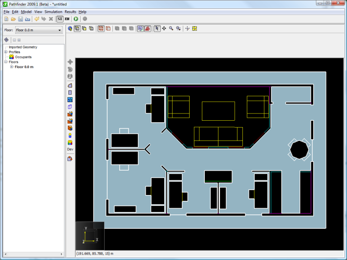 |
Working with background images requires the user to draw all rooms, doors, and stairs over the background image (Figure 91). Because the drawn navigation geometry will cover the background image, it may be preferable to make the navigation geometry transparent. This can be accomplished by selecting the drawn navigation components and lowering the opacity in the property panel. Figure 92 shows a background image with rooms and doors drawn on top, with a lowered opacity for the drawn rooms.
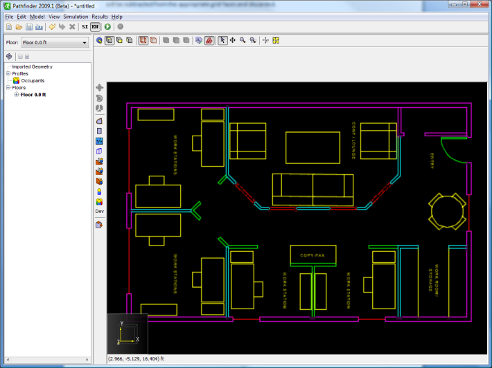 | 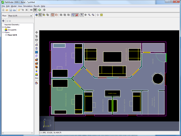 |
To draw rooms on top of a background image, refer to Rooms.
Once rooms have been extracted using the Extract Room tool, the model will still be missing doors and stairs (Figure 93). Doors and stairs must be added manually as discussed in Doors and Stairs of this guide.
One feature that may be of particular interest to help this process, however, is the internal door feature of the door tool. This feature automatically finds areas within a room that look like potential doorways and can be used to create a thick door in this area.
To use this feature:
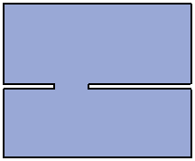 | 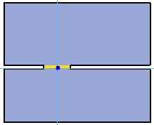 | 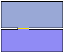 |
Sometimes when importing from 3D CAD models, extracted rooms may not be at the proper height or may have some undesired slope. These issues can be corrected either before or after extracting rooms by using the Set Z dialog (Figure 96).
To do so, follow these steps:
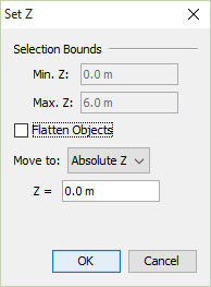
The dialog shows the following properties and options:
Materials define advanced display properties that can be applied to faces contained in the imported geometry. They are only shown when the Realistic or Realistic with Outlines option is selected in the 2D View or the 3D View, see View Options. Materials can be shared among faces; when a material is edited, all faces referencing that material are updated.
Materials are extracted from import files in different ways, depending on the file type:
To see the materials that have been imported from the DWG or PSM file, on the Model menu, select Manage Material Database. The Material Dialog will appear as shown in Figure 97.
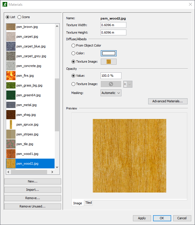
Pathfinder provides some default database materials.
Most of these materials start with the prefix, psm_ as in PyroSim.
Other materials were either created manually by the user or were imported with the CAD or PyroSim file.
Materials can be added manually by clicking New under the material list. Materials can also be created from an initial texture image on disk by clicking Import. The image is copied into the database directory. Newly created materials are added to the database, and can be used across instances of Pathfinder.
Materials can be deleted by clicking Remove under the material list. If the material exists in the database, all its associated files in the database directory will also be permanently removed.
The following material properties can be edited from this dialog:
0.5 are drawn as opaque and those with opacity < .5 are not drawn.
The following masking options are available:Additional material properties can be edited by pressing the Advanced Materials button. This will show the Advanced Materials Dialog for the currently selected material.
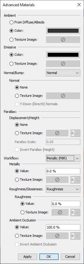
Most properties in this dialog can be specified as either a constant color/value or as a texture image.
For those properties that represent a single value as opposed to a color, such as the Roughness value for PBR workflow, a dropdown next to the texture chooser can be used to pick which color component is the source of the values.
This is useful when multiple properties are packed into a single image, but in different color components.
For instance, say the PBR parameters, metallic, roughness, and ambient occlusion, are packed into the red, green, and blue color components of a single image.
In this case, the same image can be chosen for the metallic, roughness, and ambient occlusion textures.
The dropdowns next to each texture would be set to R, G, and B, respectively.
The following material properties can be edited from this dialog:
Depending on which workflow is selected, the following additional properties are provided:
ao_inverted = 1.0 - ao_texture).
This is useful when the ambient occlusion texture specifies the amount of occlusion (increasing values lead to more occlusion) rather than amount of visible light (lower values lead to more occlusion).Sometimes the imported data may not be organized in a convenient manner. For instance, it might be desirable to change some feature of all the windows, but the windows in the model may not be in the same group, making it difficult to select all of them at once.
In cases such as these, the similar objects may have the same color. If so, right click one of the objects, and choose Select All by Color. Alternatively, choose Select All by Material. This will find all objects with the same color or material and select them, making it easy to change some shared property or move them into another group for easy selection later.
Pathfinder can use the PLOT3D data output from FDS to create time history data for each occupant as they move throughout the simulation. In cases where FDS PLOT3D output data is available for \(CO\) Volume Fraction, \(CO_{2}\) Volume Fraction, and \(O_{2}\) Volume Fraction; Pathfinder will also output Fractional Effective Dose (FED) for each occupant specified. In cases where FDS PLOT3D output data is available for SOOT Visibility, occupants maximum speed can be reduced to simulate movement through smoke (see Profiles).
Enabling this feature causes simulations to require additional runtime because of the additional processing load relating to reading the FDS output files and mapping PLOT3D data to occupants.
To enable FDS Integration:
The dialog (Figure 99) will display information about the attached SMV file and indicate which quantities were found.
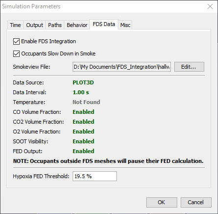
Pathfinder saves the location of the SMV file but does not embed any FDS output data within the Pathfinder model itself. Modifying and re-running the FDS simulation can change the results of subsequent Pathfinder simulations. Moving the FDS output data to a different location can cause FDS integration to fail until the location of the of the SMV file is updated.
When loading a PTH file with FDS Integration enabled, Pathfinder will verify the location of the SMV file and issue a warning if the SMV file does not exist in the expected location. In some cases, Pathfinder can automatically update the location of the SMV file and will indicate that the update has occurred in the warning.
To enable FED and PLOT3D quantity output for one or more occupants:
Once the simulation has completed, output data is available for each specified occupant in the output folder (see Occupant History).
For information on how FED is calculated or how its use was verified in Pathfinder, see (Pathfinder Technical Reference, n.d.) and (Pathfinder Verification and Validation, n.d.) documents respectively.
When viewing occupants as people in either Pathfinder or Pathfinder Results, occupants and vehicles are represented by a 3D avatar. Avatars are chosen in either the Edit Profiles dialog (see Profiles) or the Edit Vehicle Shapes dialog (see Vehicle Shapes). While Pathfinder ships with many avatars, they might not cover all modeling scenarios. Custom avatars can be imported into Pathfinder to meet additional requirements.
The following file formats are supported for importing custom avatars, listed in order of preference with the most preferred first:
Avatar files should follow these rules if possible:
Occupant avatars have the following additional constraints:
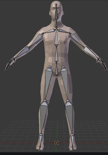
There are a variety of sources for custom avatars. They can either be purchased or downloaded online from third-party vendors specializing in 3D models or they can be created using third-party tools. Pathfinder has been successfully tested with avatars provided from the following sources:
To import a custom occupant avatar, perform the following steps:
Choose the desired file that contains the occupant avatar to import.
This will copy the avatar file along with some other supporting files into %APPDATA%/Pathfinder/models/md5/avatarname , where avatarname is the name of the avatar file.
To import a custom vehicle shape avatar, perform the following:
Choose the desired file that contains the vehicle avatar to import.
This will copy the avatar file along with some other supporting files into %APPDATA%/Pathfinder/models/props/avatarname , where avatarname is the name of the avatar file.
After importing a custom avatar, it may need further adjustments in order to display correctly. The following is a list of recommendations for fixing avatar issues:
| Problem | Cause | Fix |
|---|---|---|
| Avatar has missing textures. | Avatar file was an FBX without embedded textures, or an OBJ, DAE, or glTF file. | Copy image and mesh data files from original avatar location to target avatar location under %APPDATA%/Pathfinder/models. |
| Some or all of occupant avatar body parts do not move during animations. | The file might not be rigged or might not follow common joint naming conventions. | If the file is not rigged, there is currently no fix. If it is rigged, however, apply a joint name map in the avatar’s JSON file as described in Joint Name Map. |
| Avatar is facing the wrong direction. | Avatar in originating file was not facing the front. | Apply a mesh::transform::rotate transform in the avatar’s JSON file as described in Avatar JSON File. |
| Avatar is too big/too small. | Avatar was not modeled with realistic units or the units were wrong/unspecified in the avatar file. | Adjust the mesh::transform::scale factor in the avatar’s JSON file as described in Avatar JSON File. |
| Avatar is offset from the actual occupant location. | Avatar was not located at the origin in the source avatar file with feet on the ground. | Apply a mesh::transform::offset transform in the avatar’s JSON file as described in Avatar JSON File. |
| Avatar appears to slide/skate when walking. | Avatar has different proportions than those assumed by the importer. | Override Pathfinder’s provided move animation in the avatar’s JSON file and adjust the move_clip::naturalSpeed property as described in Avatar JSON File. |
| Other | Avatar type is unsupported by Pathfinder. | Contact support@thunderheadeng.com to report. |
The avatars that ship with Pathfinder have been optimized for use in Pathfinder Results, allowing many thousands of occupants to be displayed onscreen at once with good performance. Custom avatars are not optimized for Pathfinder Results, as they contain no level-of-detail information and often contain much more detail than is necessary for displaying thousands of occupants. Using custom avatars will likely result in reduced results display performance compared to using avatars supplied by Pathfinder.
Currently the only ways to mitigate this problem are to either limit the number of occupants using the custom avatars or use custom avatars that are designed with low polygon counts and/or low-resolution textures.
When avatars are imported into Pathfinder, they are copied into the %APPDATA%/Pathfinder/models/ location, which limits their use to the current user on the current machine.
If the results of a Pathfinder model containing these custom avatars are loaded by another user or on another machine, the occupants using the custom avatars will look like the Mannequin model that ships with Pathfinder.
To make these custom avatars available to others users, perform the following from the computer and user account from which the avatars were imported:
%APPDATA%/Pathfinder/modelsmd5.
If copying vehicle avatars, navigate to props.%PROGRAMDATA%/Pathfinder/models.
If this location does not yet exist, create it.md5.
If copying vehicle avatars, create/navigate to props.When viewing occupants as people in Pathfinder Results, occupant motion is driven by skeletal animations. Animations are chosen based on tags specified in the Edit Profiles dialog (see Profiles). While Pathfinder ships with basic animations including walking and standing idle, these might not cover all modeling scenarios. Custom animations can be imported into Pathfinder to meet additional requirements.
Typically, animations are designed in 3D modeling software for a specific avatar or are created from motion capture from an actor in a studio. The avatar/motion capture model is typically represented as a skeleton with a joint hierarchy. The animation data is simply transformations of the skeleton’s joints over time.
Animations can be stored in various file formats, such as FBX, usually exported from 3D modeling software.
Depending on the file format, the animation file may be able to contain a single animation or multiple and may optionally include the avatar for which the animation was created.
Repositories of animations can be found online, such as https://www.mixamo.com/.
While each animation is designed for a specific avatar, once it is imported into Pathfinder it can be used with any avatar. This happens through a process called retargeting, where Pathfinder will analyze the animation along with some information about the originating avatar, and then adjust the animation to better match the target avatar, even if the target has vastly different limb proportions or features than the original.
In order for this retargeting process to work well, animation files should follow the these rules if possible:
FBX file.The animation file may optionally include the originating avatar as well as the animation. If it does, the animation file is the only file necessary to import into Pathfinder; however, the file may be quite large. If the file does not contain the avatar, a separate file containing the avatar will also be necessary to import into Pathfinder.
There are a variety of sources for custom animations. They can either be purchased or downloaded online from third-party vendors specializing in 3D animations or they can be created using third-party tools. Pathfinder has been successfully tested with animations from the following sources:
A free online source for high quality character models and animations. This service provides mostly fantasy characters, but the supplied animations are quite diverse. Available at https://www.mixamo.com/.
To import a custom animation into Pathfinder, perform the following steps:
%APPDATA%/Pathfinder/models/anims/clips and %APPDATA%/Pathfinder/models/anims/meshes, respectively.In the Animation Datatabase Dialog animations can be imported, renamed, and deleted.
By default, the list on the left shows all imported animations; however, the field above the list can be used to filter the list by tag.
For instance, enter upright and press ENTER to see all animations containing the upright tag.
Add additional tags to further refine the search.
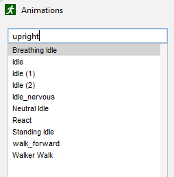
The following properties can be entered in the Import Animation Dialog and the Animation Database Dialog:
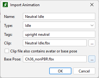
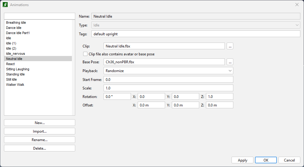 | 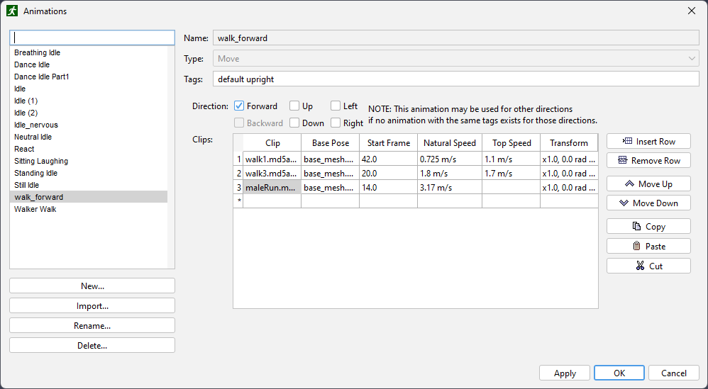 |
upright, bored, and fidgeting, it could be matched with the following tag combinations:uprightboredfidgetingupright,boredupright,fidgetingbored,fidgetingupright,bored,fidgeting1.0, as the joints will be automatically scaled to match each avatar, but this may need to be modified if the animation was authored for a very small or large avatar and the animation is unacceptable in Results.90° about the +Z axis (i.e. Rotation=90°, X=0,Y=0,Z=1).Idle animations are used when an occupant is still, such as when waiting in a queue or using a Wait Behavior Action. They have the following additional properties as seen in Figure 103:
Play Once or Repeat, as it defines the starting frame.Move animations are used when an occupant is actively moving toward a destination. They are defined slightly different than Idle animations, as they also have associated speed and direction.
Each move animation represents the occupant moving in a single direction, relative to the occupant’s orientation.
Only a single direction needs to be specified for a given set of tags, but more can be defined to improve realism in Results.
When a direction is defined, the same animation (but reversed) will be used for the opposite direction if the opposite direction isn’t explicitly defined.
For instance, if Forward is defined, but Backward is not, the reverse of the Forward animation will be used for Backward.
For all other missing directions, the direction is filled in by the nearest non-missing direction.
For instance, if Left is not defined, but Forward,Left is, then Forward,Left will also be used for Left.
When an avatar is matching an animation clip to their current relative movement direction, they will choose the clip closest to their direction.
While only one direction needs to be defined, it’s recommended that at least the following be defined (all with the same set of tags) to provide acceptable animation in Results:
Each move animation can be defined as a set of animation clips, each clip defining a different speed range for the move animation’s direction.
For instance, you might specify a walking animation clip for speeds ranging from 0 to 1.8 m/s and a running animation clip for speeds > 1.8 m/s.
Each animation clip is represented as a single row of the Clips table as shown in Figure 105, and its speed range spans from the previous clip’s Top Speed to the current clip’s Top Speed.
Clips must be listed in order of increasing Top Speed.
The Top Speed for the last clip can be left blank.
When an occupant chooses a move animation clip in Results, they will choose the one whose range spans the occupant’s current speed.
The following additional properties can be defined for move animations and their animation clips:
Forward and Right.1x speed.
For instance, the Natural Speed of a walking animation clip representing a single walk cycle might be calculated as 2*foot_stride/clip_time, where foot_stride is the distance between the avatar’s heels at full stride, and clip_time is the total clip time.
When playing the animation clip in Results for a particular occupant, the playback speed of the clip is adjusted automatically according to the Natural Speed of the animation and the movement speed of the occupant.
For instance, if the Natural Speed is 1.1 m/s, but the occupant is moving at 1.32 m/s, the animation will play at 1.2x speed (1.32/1.1).When animations are imported into Pathfinder, they are copied into %APPDATA%/Pathfinder/models/anims, which limits their use to the current user on the current machine.
If the results of a Pathfinder model using these custom animations are loaded by another user or on another machine, Results may fail to match the animation tags, causing it to display the avatars in their T- or A-poses instead.
To make these custom animations available to others users, perform the following from the computer and user account from which the animations were imported:
%APPDATA%/Pathfinder/models/animsclips and meshes.%PROGRAMDATA%/Pathfinder/models/anims.
If this location does not yet exist, create it.In Pathfinder, occupants are defined in two parts: Profiles and Behaviors.
Pathfinder uses an occupant profile system to manage distributions of parameters across groups of occupants. This system helps you control the occupant speed, size, and visual distributions. To edit occupant profiles, you can use the Edit Profiles dialog (Figure 106).
To open the Edit Profiles dialog: on the Model menu, click Edit Profiles, or double-click the word Profiles in the Navigation View.
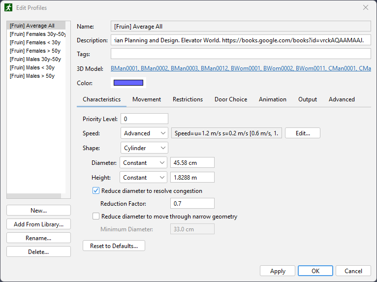
To select 3D models:
<hidden> choice is selected, no 3D Model will be shown for the occupant.By clicking the Import button in the 3D Models dialog, custom avatars can be imported into Pathfinder (see Importing Custom Avatars).
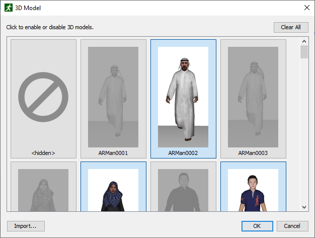
4, 6, and 12, they will behave the same as if their priorities were 0, 1, and 2, respectively.
This allows occupants of lower priority to move out of the way of those of higher priority.
This would be useful when simulating first responders that must be able to move easily through a crowd of occupants.45.58 cm is based on the average of measurements of male and female persons from nine countries (Pheasant and Haslegrave 2005).
An earlier edition is referenced by G. Keith Still in his Ph.D. thesis (Still 2000).
As shown in the Pathfinder Validation and Verification Manual, this size (and Interpersonal Distance) results in movement that matches the SFPE and experimentally measured fundamental diagrams.
Caution should be used in changing the default Diameter value.[optional] Is enabled by default and is useful in helping occupants to "squeeze" by one another in congested areas.
This factor is unitless and should be selected to be between 0 and 1.
It can be considered a way to get the benefits of elliptical occupant shape (i.e. it gives the occupants a radius corresponding to turning sideways) despite the simulator’s exclusive use of circular occupant diameters.
When occupants cannot otherwise move due to occupant-occupant collisions, this factor is multiplied against the shoulder width to shrink the collision circle and potentially allow occupants to ease through congestion.[optional] Is designed for models that have narrow seating areas and aisles.
In cases where there is some detail of the geometry that makes it difficult for full-width occupants to move, this option can be enabled to alter the occupant-geometry collision test to accommodate the narrower geometry.
The occupant-occupant collision test is not affected by this feature.
Occupants will reduce their diameter to this value only if the geometry would otherwise prevent them from further following their path.
The default value of 33.00 cm is based on the maximum depth of a human body for 95th percentile of measured individuals (Pheasant and Haslegrave 2005).
The Movement tab provides parameters related to how occupants use their surroundings.
unchecked.
In this case, the occupant’s susceptibility is multiplied by the trigger’s influence to determine the probability that the occupant will use the trigger.
See Trigger Decision for more information about how occupants choose to use triggers.The Restrictions tab specifies which components the occupant can use during path planning. For each component type, the following options are available:
The Door Choice tab provides parameters related to how occupants choose doors to exit from in each room. For more information about door choice see the (Pathfinder Technical Reference, n.d.).
The cost factor that affects the cost of waiting in a queue at a door in the occupant’s current room. Higher values increase the door’s cost in this category, making the Current Room Queue Time relatively more important.
The Animation tab provides parameters that control the animations used by occupants in the 3D Results when occupants are viewed as people. Pathfinder provides several basic animations, including walking and idling, but allows custom animations to be imported as well (see Importing Custom Animations).
The animation used by an occupant depends on their current movement state. If they are idling (not actively moving toward a destination), they will use one of the Idle Animations. Otherwise, they will use one of the Move Animations.
An occupant’s animation can be overridden by a vehicle if they are using a vehicle shape (see Vehicle Shapes).
In order to define an occupant’s animations, Pathfinder uses a tagging system.
Each animation is associated with one or more tags (see Importing a Custom Animation).
When specifying which animations to use in the occupant profile, either a pre-defined animation can be selected or a custom animation can be matched with any combination of the animation’s tags.
For instance, if a custom animation AnimA has the tags upright and alert and AnimB has the tags upright and bored, specifying an Idle Animation of upright will match with both AnimA and AnimB.
However, specifing an Idle Animation of upright bored will only match AnimB.
Enter fewer tags to match generically or more tags to match more specifically; however, be careful not to enter a combination of tags that cannot be matched by any animation.
To edit the animations, click the underlined text next to Idle Animations or Move Animations. The Animation Tags dialog will appear.
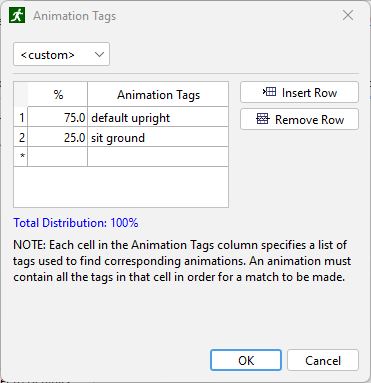
The following options are available depending on the animation type:
default,uprightAllows a distribution of animations to be specified, matched by tags.
For example, in Figure 109, approximately 75% of occupants will use animations with the tags, default and upright.
About 25% of occupants will use animations with the tags, sit and ground.
For any given row, if multiple animations match the specified tags, those animations will be distributed evenly.
For instance, if two animations match default,upright, approximately 37.5% of occupants will use one of the animations, and 37.5% will use the other.
sit,groundlay,side,injureddefault,lay,supinedefault,uprightOccupants lie on their back facing upward.
Tags: default,lay,supine
default,wheelchairThe Output tab provides the Output Detailed Data option. When checked, additional output data files are generated for each occupant using this profile. The files contain data for each time step, such as occupant speed, location, etc. (see Occupant History).
The Advanced tab provides the following parameters:
1.5 s and the default maximum speed of 1.19 m/s, the occupant will look ahead 1.785 m from their current position to detect potential collisions and calculate costs.Enables social distancing with all other occupants.
Allows social distancing with specific occupants.
With this option, you can choose to either Accept or Reject occupants with the specified tags (see Occupant Tags).
For example, in the image below, the profile’s occupants will enable social distancing with other occupants who have the both the tags, suspicious and stranger.
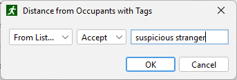
Each of these parameters (except on/off parameters) can be set using a constant value, a uniform distribution between two values, or either a normal (Gaussian) or log-normal distribution (see Stochastic Parameters).
Each occupant in the Pathfinder model is linked to one profile. Profile parameters can be edited in the profiles dialog at any time and the occupants using that profile will be automatically updated. Occupants' profiles can be set when adding the occupants or by selecting the occupants after being created and editing the Profile box in the property panel.
In most cases, users only need to enter the maximum speed of an occupant in the Characteristics tab of the Edit Profiles dialog. The actual speed of the occupant throughout a simulation will vary according to this speed and a set of assumptions from the Engineering Guide to Human Behavior in Fire (SFPE 2019), which takes into account the type of terrain being traversed (stairs, ramps, etc.) and the density of surrounding occupants (see (Pathfinder Technical Reference, n.d.)).
Pathfinder allows for fine-grained control over the speed of the occupant, however, and the SFPE assumptions can be customized or replaced with other assumptions.
To do so, follow these steps:
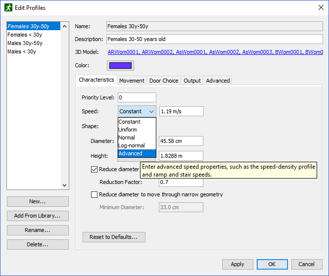
This will open the Advanced Speed Properties dialog as shown in Figure 112.
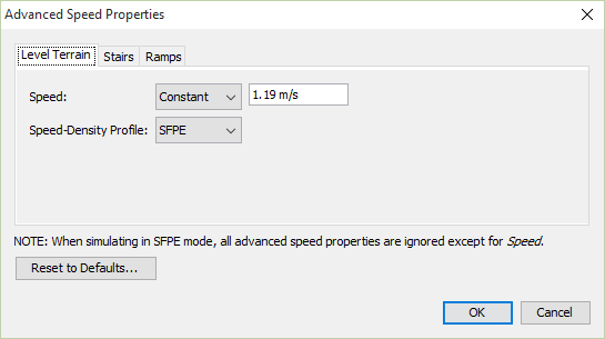
As noted in the Advanced Speed Properties dialog, when simulating in SFPE mode, only the maximum speed property is used. All others in the Advanced Speed Properties dialog are ignored.
Clicking Reset to Defaults in the Advanced Speed Properties dialog will reset all advanced speed properties to their default values in Pathfinder.
Each tab in the dialog allows the customization of occupant speed on each terrain type in Pathfinder, including Level Terrain, Stairs, and Ramps.
The Speed Density Profile can be used to set the occupant’s speed as a function of the surrounding occupant density, also known as the fundamental diagram. One of three options may be chosen for the profile:
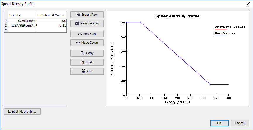
The following properties may be entered in the Stairs tab:
The above parameters define a factor that is multiplied by occupant’s maximum speed to determine their speed up or down stairs.
The factor may be specified in one of three ways:
Additionally, the Speed-Density Up and Speed-Density Down parameters have the From Level Terrain option. This option forces the occupant to use the same speed-density profile as specified on the Level Terrain tab when the occupant travels up or down stairs.
The Ramps tab has nearly identical properties available as on the Stairs tab. The only difference is that Speed Fraction Up and Speed Fraction Down are entered in terms of the ramp’s geometric slope rather than step slope. The geometric slope is determined per triangle in the resulting navigation mesh and depends on the triangle’s normal direction.
Many parameters, including speed, can be specified by a constant value or in terms of a probability distribution.
Pathfinder supplies inputs for the following distributions:
| Distribution | Description |
|---|---|
| Constant | Specifies a constant value. |
| Uniform | Generates random values that are uniformly distributed between the specified minimum and maximum parameters. |
| Normal | Generates random values that are normally distributed from the specified mean and
standard deviation, as shown in the following equation: \(f(x) = \mu + \sigma x\) |
| Lognormal | Generates random values that are lognormally distributed from the specified location andscale parameters, as shown in the following equation:
\(f(x) = e^{\mu + \sigma x}\) |
Each occupant has a unique random seed that determines the specific values generated from a profile distribution. Each of these occupant-specific values can be seen by selecting an individual occupant. These specific values will never change unless the distribution is changed in the profile or a new seed is manually generated for the occupant. This ensures that two simulation runs with the same input model will give the same answer. New seeds can be generated for occupants by right-clicking the occupants and selecting Randomize.
For an example of the effects of the changing the seed or profile, consider the following scenario:
1 m/s to 2 m/s.1.6 m/s based on the occupant’s profile.1.6 m/s..5 m/s to 1 m/s..6 m/s, which is used for all subsequent simulations..91 m/s to the occupant.When occupants are selected, their property panel appears as shown in Figure 114. Occupants can be given custom profile data once they are added to the model. This can be done by selecting a set of occupants and checking the box next to the parameter to be customized.
Percentage-based distributions can also be used to assign occupant profiles and behaviors to a group of occupants, see Redistributing Profiles and Behaviors.
Customized properties will be overwritten if an occupant switches their profile or changes a property during simulation, see The Change Profile Action and The Change Profile Property Action.
When using custom profile data, only constant values can be used for occupant parameters. In addition, once a parameter is customized, any changes to that parameter in the profile will not affect the customized value.

Occupants with individually customized parameters can easily be found by right-clicking all or a sub-set of occupants and selecting Select Customized Occupants from the right-click menu if any exist in the selection.
Profiles can be saved and reused using profile libraries (Figure 115). Profile libraries are managed in the Profile Libraries dialog. To open the Profile Libraries dialog, on the Edit Profiles dialog, click Add From Library Alternatively, the Profile Libraries dialog can also be opened by clicking Edit Profile Libraries on the Model menu.
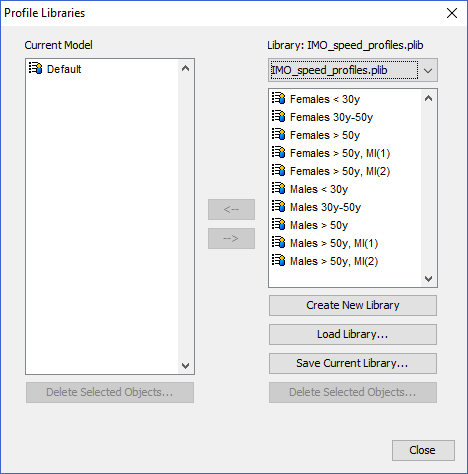
The list on the left side of the dialog shows all profiles contained in the current Pathfinder model.
The list on the right side of the dialog shows all profiles stored in the profile library.
Profiles can be moved between the lists using the buttons in the middle of the dialog.
Create New Library clears the list of library profiles so that a new library can be created.
Load Library opens a profile library from file.
Pathfinder supports loading profiles from profile library files (PLIB) and from standard Pathfinder model files (PTH).
To create a Pathfinder library file (PLIB) based on profiles in the current model:
The dropdown menu on the right side of the dialog can be used to load predefined libraries.
To fill the predefined libraries box, Pathfinder scans two locations: a folder in the Pathfinder installation shared by all users and a folder in the current user’s APPDATA path, see Table 10.
| PLIB File Location | Suggested Use |
|---|---|
C:\Program Files\PyroSim 20XX\lib\profiles(or alternate install folder) | Built-in libraries included with Pathfinder. Administrator access is required to modify this location. Changes to PLIB files from this location will affect all users sharing the computer. |
%APPDATA%\Pathfinder\profiles | Recommended location for storing PLIB files. Non-admin users have write access to this folder. Changes to PLIB files in this location will affect only the current user. |
All predefined profile libraries are opened as read-only to prevent accidental modification. To modify a library, you will need to resave to overwrite the existing PLIB file. See Appendix A, for more information on the occupant profiles provided with Pathfinder.
An occupant can be assigned a vehicle to use during the simulation. When using a vehicle, an occupant uses the shape of the vehicle rather than the default cylinder shape when performing collision detection. Any convex polygon can be used as the vehicle shape.
Vehicle shapes are not intended to be used as shapes of regular occupants as vehicle movement is fundamentally different from occupant movement. Unlike regular occupants, vehicles are not allowed to move sideways. Consequently, the vehicles follow a different path, which accounts for this movement restriction. Vehicles also avoid collisions with other occupants and walls differently from regular occupants. Finally, vehicle movement uses more complex calculation, which can increase the run time of the simulation.
The vehicles can be created and customized in the Edit Vehicle Shapes dialog (Figure 116). To open the Edit Vehicle Shapes dialog: on the Model menu, click Edit Vehicle Shapes.
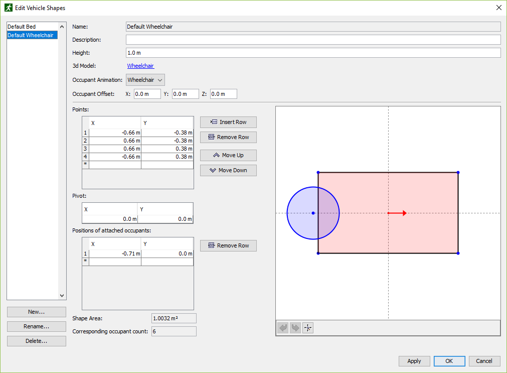
The Description box provides a place to enter descriptive text. This value is not used outside the Edit Vehicle Shapes dialog.
<shape> is chosen as the 3D model, an extruded polygon is used as the 3D model for the vehicle.
The color of the extruded polygon will match the color of the occupant.
Custom avatars can also be imported as described in Importing Custom Avatars.(0,0,0) will put the occupant’s 3D model at the vehicle’s origin as shown in the vehicle preview.The Vehicle Preview shows a graphical preview of the projected shape of the vehicle and provides additional capability to add, remove, and change points of the vehicle shape, the pivot location, and the positions of attached agents.
The dashed lines depict the horizontal and vertical axes. Their intersection (by default point x=0, y=0) is the pivot of the vehicle, around which the vehicle body rotates. The red arrow points in the direction of the movement of the vehicle. The pivot can be moved both inside and outside of the vehicle shape.
A point can be added to the vehicle shape or positions of attached occupants by right clicking inside the graphical editor. When moving the cursor close to a point, the point changes its color to orange indicating that it can be selected. A selected point changes its color to yellow. This selection is also displayed in the point editors on the left side of the dialog.
Any point can be moved by selecting and dragging, and it can be deleted by right clicking and selecting the Delete Point option. Mouse wheel can be used to zoom in and out, and mouse dragging can be used to move around. Reset View button resets the view so that all points are visible. The Undo/Redo buttons can be used to undo/redo any action within the 2D Graphical Editor.
A warning will appear at the bottom of the dialog in case constraints like minimum number of points in the vehicle shape, convexity, distance of assisting occupants from the vehicle shape etc. are violated.
For more information about the navigation of polygonal shapes in Pathfinder see the Pathfinder Technical Reference (Pathfinder Technical Reference, n.d.).
Behaviors in Pathfinder represent a sequence of actions the occupant will take throughout the simulation. Once they occupant has completed all actions, they are removed from the simulation. Actions may be added that can make the occupant wait or travel to a destination, such as a room, point, or exit.
The last destination for the occupant can be thought of as the occupant’s sink. By default, there is one behavior in the model called "Goto Any Exit". This behavior simply makes the occupant move from their starting position to any exit present in the model by the fastest route.
As with profiles, any number of occupants can refer to a single behavior. Any changes to the behavior will be reflected in referring occupants.
To create a new behavior:
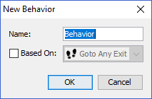
With the new behavior selected, the behavior property panel will appear as shown in Figure 118.
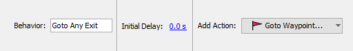
Additional actions can be added to any behavior, such as going to a room, a waypoint, an elevator, or simply waiting in place. To add an action, select a behavior or existing behavior action. The property panel (Figure 119) will show a drop-down button with the description of an action that can be added. To add the currently shown action, simply click the button. To add a different action, click the down-arrow shown to the right of the button and select the desired action from the behavior actions list.
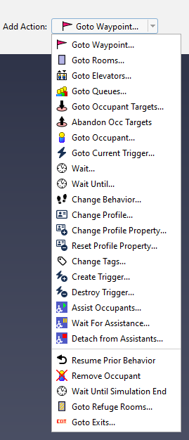
Once the desired action is clicked, a creation panel will be shown above the 3D/2D View depending on the action. Enter the desired parameters in the creation panel as discussed in the following sections, and then click Create to create the action and append it to the behavior. If the behavior itself was selected when adding the action, then the new action will be appended to the end of the list. If, instead, an action was selected when the new action was created, then the new action is inserted directly after that selected action. If the action is an ending action (includes all actions below the separator in the behavior actions list), the action will always be added at the end. If the behavior already has an ending action, it will replace the existing ending action.
Actions always occur in the order shown in the Navigation View. For instance, as shown in Figure 120, an occupant using "Behavior1" would first go to any elevator, then go to "Room00", then wait for 20 seconds, then go to "Room09". After reaching "Room09", the occupant will be removed from the simulation. The actions can be reordered at any time by dragging and dropping an action in the list in the Navigation View.
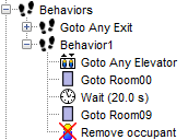
| Action | Ending Action? | Description |
|---|---|---|
| Goto Waypoint | No | Specifies that an occupant should go toward a specific point on the navigation mesh. |
| Goto Rooms | No | Specifies that an occupant must select a room out of a set, and go to it. |
| Goto Elevators | No | Tells an occupant to use elevators. |
| Goto Queue | No | Specifies that an occupant should join a designated Queue. |
| Goto Occupant Targets | No | Tells an occupant to reserve an Occupant Target out of a set and travel to the target. |
| Abandon Occ Targets | No | Tells an occupant to abandon Occupant Targets they have previously reserved. |
| Goto Occupant | No | Tells an occupant to go to another occupant with a specified tag. |
| Goto Current Trigger | No | Tells an occupant to go to the location of their currently used Trigger. |
| Wait | No | Tells an occupant to wait in their current location for a specified amount of time. |
| Wait Until | No | Instructs an occupant to delay their movement until a specified simulation time passes. |
| Change Behavior | No | Instructs an occupant to change a behavior to a new behavior picked randomly from a behavior distribution. |
| Change Profile | No | Instructs an occupant to change to a different profile picked randomly from a profile distribution. |
| Change Profile Property | No | Instructs an occupant to change one of their properties to a specified value. |
| Reset Profile Property | No | Instructs an occupant to reset a property back to their profile value. |
| Change Tags | No | Instructs an occupant to change their Tags. |
| Look At | No | Instructs an occupant to orient their body towards another occupant. |
| Look Ahead | No | Instructs an occupant to orient their body toward their goal. |
| Create Trigger | No | Creates triggers that may influence other occupants. |
| Destroy Trigger | No | Destroys triggers created by an occupant. |
| Assist Occupants | No | Instructs the occupant to join an assisted evacuation team and begin assisting occupants who request assistance from that team. |
| Wait For Assistance | No | Indicates that the occupant should wait for assistance from other occupants. |
| Detach from Assistants | No | Detaches a client from their assistants, allowing the assistants to continue helping other clients. |
| Resume Prior Behavior | Yes | Instructs the occupant to continue using the behavior prior to the current behavior. |
| Remove Occupant | Yes | The occupant will be removed from the simulation. |
| Wait Until Simulation End | Yes | The occupant will wait in their current location until the end of the simulation. |
| Goto Refuge Rooms | Yes | Instructs the occupant to go to one of a set of rooms marked as refuge areas. |
| Goto Exits | Yes | Instructs an occupant to take the fastest route to a set of exits. |
A Goto Waypoint action specifies that an occupant should go toward a specific point on the navigation mesh. Once they arrive within a certain radius of the point, they will move on to the next action in their behavior.
To add one of these actions:
These parameters can be entered manually in the creation panel or be filled in by clicking a point on the navigation mesh in the 3D or 2D View or click-dragging to specify the location+arrival radius. When clicking or click-dragging, the action is created when the mouse button is released.
A Goto Rooms action specifies that an occupant must select a room out of a set, and go to it. Once they cross a door into the room, they are considered to be in the room and can move on to the next action in their behavior. If multiple rooms are specified for the action, the occupant will go to the one that is fastest to reach.
To add a Goto Rooms action:
A Goto Elevators action tells an occupant to use elevators. When using this action, an occupant will go to a specified elevator, call it, wait for it to arrive, enter it, and then wait for it to reach their target floor. Once they reach their target floor, they can begin their next action. If multiple elevators are specified for the action, the occupant will use the one that allows them to reach their target floor fastest.
To add a Goto Elevators action:
A Goto Queue action specifies that an occupant must select a Queue out of a set, and go to it. When using this action, the selected Queue will direct the occupant’s movement through available queue paths and service points and then releasing the occupant to the next behavior action once it is complete.
To add a Goto Queue action:
A Goto Occupant Targets action tells an occupant to reserve a single Occupant Target out of a set of targets and then navigate toward the reserved target (see Occupant Targets). Once the occupant has reserved a target, they will hold the reservation indefinitely as they move toward it and then perform other behavior actions. They will even maintain the reservation after they have exited the model or have otherwise been removed from the simulation. Holding a reservation to a target prevents other occupants from using that target and allows the occupant to return to it if they have been distracted by a Trigger.
The occupant will only give up the reservation if they encounter an Abandon Occ Targets action in their behavior list that indicates they should do so. This action can either be part of their assigned behavior or can be part of a Trigger behavior (see Triggers).
The occupant reaches their chosen target and is finished with the Goto Occupant Targets action when their body shape intersections a circular area surrounding the target location with a 0.5 m radius.
To add a Goto Occupant Targets action:
An occupant uses their Preference parameters to decide the order in which they attempt to reserve targets.
For more information on the Occupant Target reservation system, how occupants choose targets, and how conflicting requests are resolved see Occupant Target Reservation System.
The Abandon Occupant Targets action cancels one or more of an occupant’s previous Occupant Target reservations. Abandoning a target allows other occupants to reserve the target using a Goto Occupant Targets action.
To add an Abandon Occ Targets action:
A Goto Occupant Action tells an occupant to select another occupant and seek to them.
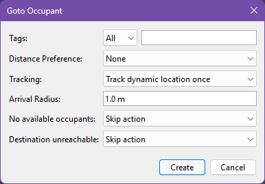
A source occupant uses the following parameters to determine which destination occupant to select and how to seek to them:
The source occupant will wait until a destination occupant can be found.
A Goto Current Trigger action tells an occupant to seek to their currently used Trigger. If the occupant is not using a trigger, this action will be skipped.
To add a Goto Current Trigger action:
The following properties are available for the Goto Current Trigger action:
The occupant records the location of their current trigger when the action is started, and then seeks that point until they are within the Arrival Radius and there is a clear line-of-sight to the point. The trigger might not still be at the point when the occupant arrives.
A Wait action tells an occupant to wait in their current location for a certain amount of time. Once that time has elapsed they will begin their next action.
The manner in which they wait varies depending on the destination of their most recent seek action and the Wait Mode, which can be the following values:
The following provides more detail about how an occupant will wait for the various types of previous seek actions and Wait Modes:
| Prevoius Seek Action | Wait Mode: Avoid Others | Wait Mode: Wait in place with collisions | Wait Mode: Wait in place without collisions |
|---|---|---|---|
| Goto Waypoint | The occupant will try to stay close to the center of the waypoint while avoiding others. | The occupant will move to the center of the waypoint without avoiding others, where they will stay once reached. Others will still avoid them. | The occupant will move to the center of the waypoint without avoiding others, where they will stay once reached. Others can pass through them. |
| Goto Rooms | The occupant will try to move toward the farthest point in the room away from all active doors, allowing other occupants to enter the room. | The occupant will move slightly into the room and then wait without moving. Others will still avoid them. | The occupant will move slightly into the room and then wait without moving. Others can pass through them. |
| Goto Elevators | The occupant will stay in the elevator they traveled in once it reaches the occupant’s target floor. | Should not be used. | Should not be used. |
| Goto Queue | The occupant waits in the room of the used service in the same manner as Goto Rooms. | The occupant stands still at their used service while others try to avoid them. Others can still use this service, however, which may cause excessive congestion. | The occupant stands still at their used service, while others continue to use the service and can pass through them. |
| Goto Occupant Targets | The occupant uses the Occupant Target reservation system as described in Occupant Target Reservation System to ensure they have a reserved target. If they have reached the target, they will wait at it in the same manner as the Goto Waypoint action. If they haven’t reached it, they will travel to the target and then wait. | The occupant uses the Occupant Target reservation system, travels to their reserved target, and then stands still at the target. Others try to avoid them. | The occupant uses the Occupant Target reservation system, travels to their reserved target, and then stands still at the target. Others can pass through them. |
| Assist Occupants | The occupant waits in the room where they detached from the assisted occupant in the same manner as Goto Rooms. | The occupant waits in the room where they detached from the assisted occupant and then stands still. Others must avoid them. | The occupant waits in the room where they detached from the assisted occupant and then stands still. Others can pass through them. |
To add a Wait action:
A Wait Until action instructs an occupant to delay their movement until a specified simulation time passes. This action is useful for synchronizing movement of many occupants at a time. Occupants fill space during a Wait Until action per the same rules described for the Wait action. Wait Until actions can be specified using three different approaches: occupants can wait until a specific time, the next in a list of times, or the next time in a periodic function.
To add a Wait Until action:
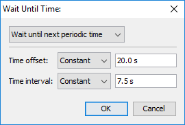
Within the Wait Until Time dialog, there are three sub-actions available:
The list of times is then generated from these parameters. For example, if Time offset is set to 60 s, and the Time interval is set to 10 s, the list of times will be [60, 70, 80, 90, 100, …]. Similarly to the Wait until next scheduled time action, when the occupant begins this action, they will pick the next time in the list and wait until that time passes.
Both the Time offset and Time interval may be specified as distributions.
In this case, each occupant will be given a unique list of times to choose from.
For instance, if the Time offset is set to a uniform distribution of [50,60] and the Time interval is set to be constant at 10 s, one occupant may get the list, [52.3, 62.3, 72.3, 82.3, …], and another occupant may get the list [59.2, 69.2, 79.2, 89.2, …].
This action causes an occupant to switch its behavior. After this action, the occupant will start performing actions from a different behavior. This new behavior is randomly selected from a given behavior distribution. Besides other behaviors, the same behavior and No Change can also be selected. If the occupant changes behavior to its current behavior, the behavior will be restarted. If the occupant selects to make No Change, the Change Behavior action will have no effect. It is possible to create loops in the behavior references. That way the occupant might keep performing the actions forever (until the end of the simulation). Note that depending on the specific setup, it is possible that actions that come after a Change Behavior action will not be performed by the occupant.
See Discrete Distributions for help specifying behavior distributions.
This action causes an occupant to change their profile, which will override all parameters settable in an occupant profile (Profiles).
This can be used to change an occupant’s speed, shape, avatar, etc., throughout a simulation.
The chosen profile is selected from a list of possible profiles, including a No Change item that will prevent the occupant’s profile from changing.
For profile parameters that are specified as distributions (e.g. max speed), a given occupant will always select a value from the same part of the distribution for that parameter. For instance, if a given occupant starts with a profile whose max speed is a normal distribution, and the occupant’s speed is chosen from the 25th percentile, any subsequent profile changes will also lead to the occupant’s speed being chosen from the 25th percentile of the new speed distribution. This ensures that if an occupant’s profile is changed, that parameter will remain consistent for the occupant. In addition, if the parameter does not change with a profile change, the occupant will maintain the previous value. For value sets, such as occupant avatars, it is guaranteed that the occupant will maintain the same value only if the new profile uses the exact same set of values as the previous.
Profile changes can also be used to change an occupant’s shape. It can change from a normal cylinder shape to a vehicle shape. It can also change from one vehicle shape, such as a bed, to another shape, such as a wheelchair. Because vehicles can be used with assisted evacuation (see Assisted Evacuation), take care when switching between shapes during assistance. If an occupant is to change vehicles during assistance, for correct functionality it is best to detach from assistants before changing shapes using a Detach from Assistants action and then re-attach after changing shapes using a Wait for Assistance action.
See Discrete Distributions for help specifying profile distributions.
This action causes an occupant to override a single parameter settable in an occupant profile (Profiles). This can be used to change an occupant’s speed, shape, avatar, etc., throughout a simulation.
To add a Change Profile Property action:
Click Create.
For properties that are specified as distributions, a given occupant will always select a value from the same part of the distribution for that property. For instance, if a given occupant starts with a profile whose max speed is a normal distribution, and the occupant’s speed is chosen from the 25th percentile, any subsequent speed property changes will also lead to the occupant’s speed being chosen from the 25th percentile of the new speed distribution. For value sets, such as occupant avatars, it is guaranteed that the occupant will maintain the same value only if the new property has the exact same set of values as the previous.
Property changes can also be used to change an occupant’s shape. It can change from a normal cylinder shape to a vehicle shape. It can also change from one vehicle shape, such as a bed, to another shape, such as a wheelchair. Because vehicles can be used with assisted evacuation (see Assisted Evacuation), take care when switching between shapes during assistance. If an occupant is to change vehicles during assistance, for correct functionality it is best to detach from assistants before changing shapes using a Detach from Assistants action and then re-attach after changing shapes using a Wait for Assistance action.
This action causes an occupant to reset a parameter to the value defined in their occupant profile (Profiles). This can be used to reset changes previously performed by the Change Profile Property action.
To add a Reset Profile Property action:
This action causes an occupant to change their tags, optionally replacing the occupant’s current tags. See Occupant Tags for other ways tags can be applied to occupants.
To add a Change Tags action:
This action causes an occupant to orient their body toward another occupant and continue doing so while performing their next behavior actions until they encounter a Look Ahead action. While the occupant has a look-at target, they will orient their body as long as they have a clear line-of-sight to the destination occupant’s center, according to the navigation mesh. If they do not have clear line-of-sight, they will orient their body toward their goal instead.
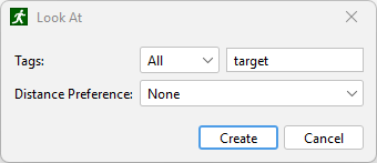
A source occupant uses the following parameters to determine which destination occupant to select:
This action causes an occupant to orient their body toward their goal. This can be used after a Look At action in order to reset their orientation.
This action creates new Triggers based on Trigger Templates. This can be used to influence the behavior of other occupants in the simulation. It can also be used to create moving triggers.
To add a Create Trigger action:
Triggers created by this action do not influence the occupant that created them. They will be automatically destroyed when that occupant is removed from the simulation.
This action destroys triggers previously created by Create Trigger.
To add a Destroy Trigger action:
All triggers with the selected templates previously created by the occupant will be destroyed by this action.
This action is used in assisted evacuation models as discussed in Assisted Evacuation. This action instructs the occupant to join an assisted evacuation team and begin assisting occupants who request assistance from that team. When an occupant joins a team, they become an assistant. Once all occupants requesting assistance have completed their actions for which they wanted assistance, the assistant will begin their next action.
To add an Assist Occupants action:
This action indicates that the occupant should wait for assistance from other occupants as discussed in Assisted Evacuation. This action requires that the occupants using it have a vehicle shape with at least one attached occupant location as discussed in Vehicle Shapes. When an occupant begins this action, they are considered to be a client, and assistants will approach the client. The client waits according to the action’s Wait Mode as described in The Wait Until Action. Once all attachment positions are filled by assistants, the client begins their next action. The assistant will stay attached to the client until either the client has completed all subsequent actions or the client begins a Detach from Assistants action as described below.
To add a Wait for Assistance action:
This action indicates that the occupant should detach from their assistant as discussed in Assisted Evacuation. When an occupant begins this action, they are considered to be a client, and currently being assisted in their movement. Once detached, the occupant can proceed to their next behavior without assistance, only if they do not require assistance to move. This action also allows the assistant to move on to the next occupant requiring assistance.
To add a Detach From Assistance action:
This action resumes the Behavior prior to the current behavior.
It can only be used for behaviors that are the target of a Change Behavior action.
For instance, suppose Behavior A has the following actions:
And Behavior B has the following actions:
The Resume Prior Behavior action will cause the occupant to follow this sequence of actions:
Behavior A)Behavior B)Behavior A)To add a Resume Prior Behavior action:
Removes the occupant from the simulation. The occupant will no longer be visible or interact with any other remaining occupants.
To add a Remove Occupant action:
The occupant will wait in their current location until all other occupants finish their behavior actions or also start a Wait Until Simulation End action. The manner in which the occupant waits is similar to the Wait and Wait Until actions and depends on the action’s Wait Mode.
To add a Wait Until Simulation End action:
This action instructs the occupant to go to one of a set of rooms marked as refuge areas as discussed in Room Properties. Like the Goto Exits action, this action must be the last action in the behavior. When an occupant reaches the refuge area, they will remain in the simulation and wait for the simulation to complete. Their behavior while waiting is described in the Wait action above. Additionally, the occupant will be tagged with "refuge_reached", as reported in the Occupant Summary and Occupant History output files as discussed in Occupant Summary and Occupant History.
This action is created similarly to the Goto Rooms action, except that only rooms marked as refuge areas may be chosen.
This action causes an agent to take the fastest route to a set of exits. Like the Goto Refuge Rooms action, this action must be last in the behavior. Once an agent goes through an exit, they are removed from the simulation and reported as having exited the model in the Occupant Summary and Occupant History output files as discussed in Occupant Summary and Occupant History.
To add a Goto Exits action:
Occupants can be added to the simulation in a number of ways. The simulation can either be pre-seeded with any number of occupants or it can have occupants continuously generated by occupant sources. When pre-seeding the model, occupants can be placed individually in the 3D or 2D view, distributed in a rectangular region of a particular room, or distributed throughout the entire area of a room.
Individual occupants can be added to the model with the Add Occupant tool ![]() .
Occupants can only be placed in pre-existing rooms, stairs, and ramps and cannot overlap other occupants or room boundaries.
Left-click a desired position with the mouse, or enter an x-y-z coordinate and press the Create button from the property panel to place an occupant (Figure 124).
.
Occupants can only be placed in pre-existing rooms, stairs, and ramps and cannot overlap other occupants or room boundaries.
Left-click a desired position with the mouse, or enter an x-y-z coordinate and press the Create button from the property panel to place an occupant (Figure 124).
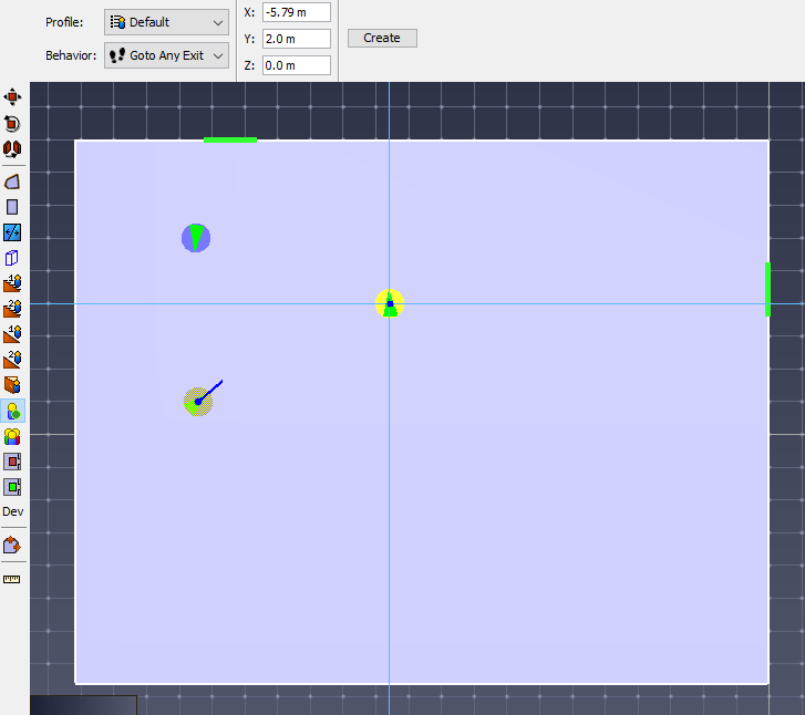
Groups of occupants can be added to the model with the Add Occupants to a Region tool ![]() .
The occupants are distributed throughout the region using parameters in the property panel as shown in Figure 127.
.
The occupants are distributed throughout the region using parameters in the property panel as shown in Figure 127.
Once the properties have been specified, there are two ways to draw the placement region:
When finished with the tool, the occupants will be placed within the designated region (Figure 126).
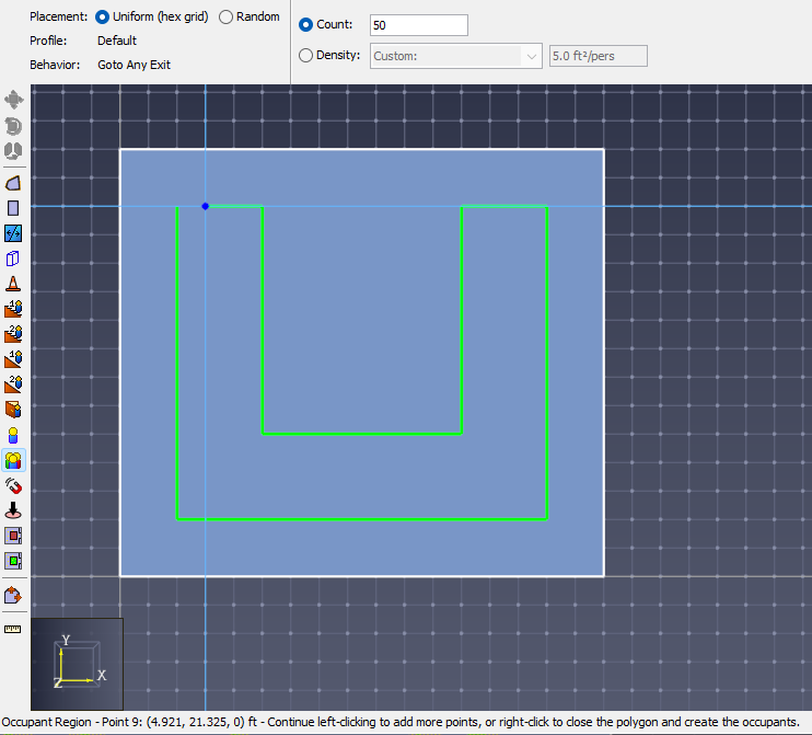 | 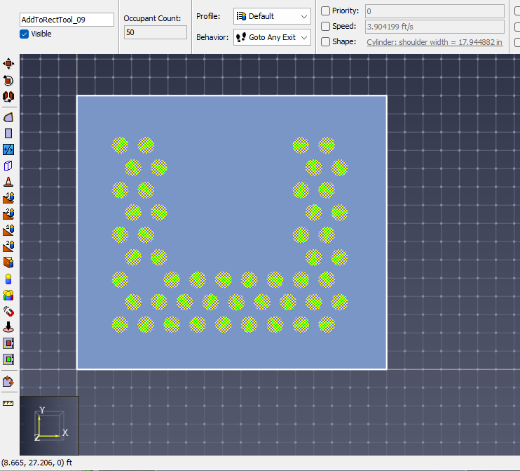 |
When an occupant is selected, the property panel allows the occupant’s name, profile, and behavior to be edited. All profile parameters are also displayed, showing exactly what value will be used for that specific occupant. Any of these parameters can be overridden by checking the box next it and entering the desired value (see Customizing Occupants).

Random placement places occupants randomly within the designated area, such that no overlapping of occupants occurs. If the number of desired occupants is too great to accomplish this, a prompt will ask whether or not to continue with overlapping occupants. Uniform placement places occupants in an orderly hex pattern, allowing greater occupant densities before overlap occurs. Again, a prompt will ask whether to continue with overlap if the density is too great.
This option specifies whether to place a set number of occupants or place enough occupants to achieve a certain density. Several template densities are provided, and Custom can be selected from the densities drop-down menu to enter a new value.
This option allows a distribution of profiles to be set for the occupants, such as specifying that 25% of the added occupants should be females < 30 years old, 30% children, etc. The label shows the currently set distribution, and if there is more than one profile defined in the model, the value can be clicked to edit the distribution. See Discrete Distributions for help specifying distributions.
This option allows the distribution of behaviors to be set and is set by specifying percentages of each behavior.
In addition to distributing occupants in placement regions, occupants can be distributed throughout entire rooms.
To do this:
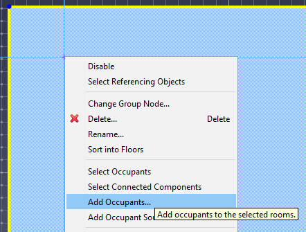 | 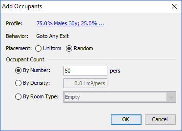 |
Occupants can also be created from existing Occupant Targets (see Occupant Targets). To do so, perform the following:
Occupants will then be generated based on the selected distribution of profiles and behaviors:
Occupants can also be created by importing their locations from a CSV file. In the CSV file, each row represents a single occupant. The file must contain three columns, specifying the X, Y, and Z coordinates in meters for each occupant location.
An optional occupant name can be specified in the fourth column. If a name is not specified in the occupant’s row then a name will be generated for them.
To import the occupants, perform the following:
Occupant sources define areas in which occupants are generated dynamically throughout the simulation.
To add an occupant source, use the Add Occupant Source tool ![]() or right click on a door or a room in the model, and select Add Occupant Source. If an occupant source that is attached to a component is later deleted from the model the user will be notified and the occupant source will either be attached to a different component or deleted.
or right click on a door or a room in the model, and select Add Occupant Source. If an occupant source that is attached to a component is later deleted from the model the user will be notified and the occupant source will either be attached to a different component or deleted.
There are three options for specifying the physical location of the occupant source within the model, as shown in Figure 130.
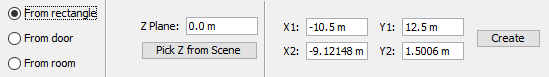
An occupant source can be defined by a rectangular region or attached to a component in the model.
Once the location of an occupant sources is defined, additional parameters that relate to the occupants that are generated can be specified. Figure 131 below shows parameters that can be specified for an existing occupant source.

Whether occupants should be traveling at their maximum velocity when they are generated by the source.
If this is set to No, the occupants will start with a speed of 0 and have to accelerate to their maximum velocity.
Each occupant source contains a non-editable seed used in the randomization of profile, behavior, and flow rate distributions. This ensures that every time a simulation is run with the same seeds, the results are deterministic. In order to generate a new set of results, however, the seeds can be re-generated. To do so, perform the following:
The occupant source Flow Rate is the rate at which new occupants will be created. There are a number of methods for specifying the flow rate as discussed below.
Specifies the flow rate as a constant value in persons / second. The occupant source will continue flowing until the simulation end time (Time Parameters).
Specifies the flow rate as a function from a table, where the flow rate can vary over time. The flow rate table editor is shown in Figure 133 below. During the simulation, at any given time, the number of occupants that are released from the occupant source is calculated based on the integral of the resulting function up to that time, minus the number of occupants who have already been released.
The editor can also be used to automatically construct a periodical step function. To do so, click the Step Function button. The Create Step Function dialog is shown in Figure 132 below. The editor with a generated step function is shown in Figure 133 below.
The following are the parameters of the step function that can be set in the Create Step Function dialog:
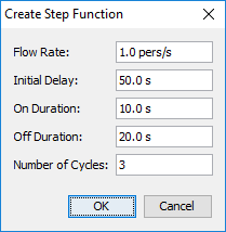
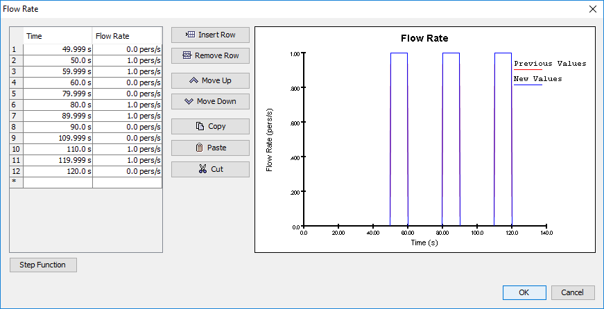
This option allows the specific occupant entry times to be specified in a table. This may be useful in re-creating observed data. The number of non-empty entries in the table determines the number of occupants who will be generated from the occupant source.
With the Scheduled flow rate option, the insertion times can be specified using timing intervals. Unlike the From Table option, the Scheduled option allows for random insertion times and instantaneous transitions between varying flow rates.
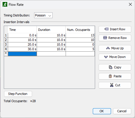
Each row of the table represents one insertion interval.
The Time column indicates the start of that insertion interval.
The Duration column indicates how long that insertion interval will last.
The end time of the interval is Time + Duration.
Intervals may not overlap.
The Num. Occupants column indicates how many occupants will be released during that interval.
The approximate flow rate for the interval is Num. Occupants / Duration.
The Timing Distribution indicates how the occupant insertion times will be distributed during each interval. The following options are available:
As with the From Table option, the Scheduled option can be used to create a step function with the Step Function button.
When Yes is selected, the occupant source will keep generating occupants regardless of how crowded its area is, which can result in overlapping occupants but will help guarantee the number of generated occupants.
When No is selected, the occupant source will only generate an occupant if the new occupant will not overlap with another occupant.
Otherwise, the occupant source will wait until the next time step to try to generate an occupant again.
The occupant source Occupant Locations table can be used to enter known locations for occupants when they enter the simulation. This might be useful, for instance, to compare a simulation to experimental data, where the exact initial positions of the occupants need to be reproduced.
In the table, enter the initial locations for each generated occupant in each row. The order of the rows matches the order in which occupants are generated by the occupant source, as determined by the Flow Rate. For instance, the first row is the location of the first generated occupant. The second row is for the second occupant, etc. If a row is left blank or there are fewer entries in the table than generated occupants, some occupants will not have a corresponding entry in the table. In this case, those occupants will be assigned a randomly generated location within the occupant source region.
For example, suppose the occupant locations table contains the following values:
| X | Y | Z |
|---|---|---|
| 1 | 0 | 5 |
| 2 | -5 | 3 |
Also, suppose the occupant source flowrate produces 5 occupants.
The first occupant will be generated at (1,0,5), the second occupant will be generated at a random location within the occupant source region, the third occupant will be generated at (2,-5,3), and the third and fourth occupants will also be assigned random starting locations.
The Initial Orientation property specifies the direction an occupant will be facing when they are generated.
If this box is unchecked, the initial orientation of the occupant is determined by the Initial Orientation property of the occupant’s profile (see Movement Tab).
If the box is checked, however, the orientation can either be set to <automatic> or to a distribution of orientation angles.
The orientation angle is specified as an angle going counter-clockwise from the positive X axis.
If the Initial Orientation is set to <automatic>, the orientation is determined as follows:
Once occupants have been created, the distribution of profiles and behaviors can be reshuffled among them.
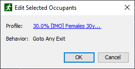
After occupants have been created, their positions can be changed to new random positions.
To randomize occupants' positions, select one or multiple rooms, and from the right-click menu select Randomize Occupants' Positions The Randomize Occupants' Positions dialog appears (Figure 136), providing the option to change room and position settings.
After clicking OK, all occupants in the selected rooms will be moved to their newly generated positions. Occupants' orientation will change too, unless it is defined locally for specific occupants or set to a constant angle in the occupants' profile.
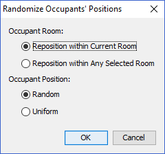
It is sometimes necessary to reduce the number of occupants in the model. The number of occupants can be decreased in each room, stair, ramp, or occupant group automatically.
To reduce the number of occupants in a component or in an occupant group, right click on the specific object and select Reduce Population A dialog will appear with the option to set the new occupant count. The deletion method can also be set.
Pathfinder can either keep random occupants, first occupants in the selection, or last occupants in the selection.
Occupants can have multiple tags applied to them. These tags act as a kind of label that can help identify related occupants during the simulation. They can be used for the following purposes:
There are multiple ways that tags can be applied to occupants, including the following:
In Pathfinder, users can define occupant-organizing structures called Queues. These can be defined as an object that consists of the following:
Occupants who join a queue will move immediately into an available service, where they will stay for a user-defined amount of time. If all services in a queue are occupied, occupants will begin to form a line along the path(s). When occupants finish their wait at the service, they will be released to their next behavior action while any occupants behind them will move forward in the queue.
As the model runs, queues will attempt to fill their service(s) as soon as they are able, filling in from occupants who have joined the structure first. If there are multiple Paths waiting for the Service(s), queues will choose from them evenly.
When it is desired that a particular path always leads into a particular service, it is important to model the scenario using a single queue. If an occupant has a choice between multiple queues with a similar structure of paths and services, it is best to specify all of the potential queues in the Goto Queue behavior action.
Services are the destinations of a Queue, defined by a point on the navigation mesh. When an occupant reaches one, they will wait at this point and then be released to their next behavior action; associated parameters designate the time for the occupant to wait before the queue releases them.
Paths are the routes of a Queue that occupants follow and wait at to reach a service. They are linear sets of Nodes on the navigation mesh, and occupants will form a line along the path between the nodes, moving forward to the exit end of the path and to the service when they are able.
Once created, paths have the following parameters:
A path’s Nodes are the points in space that defines the route. The points are ordered from top to bottom in the tree, representing the nodes by distance from a service. They may be shuffled around or deleted in any order once created. Additional Nodes may be added to or deleted from a path after the initial path is created. Path Nodes can be moved to modify the path through the model.
Pathfinder supports assisted evacuation scenarios, in which some occupants may assist other occupants. This is particularly useful in hospital evacuations and other scenarios where there may be some disabled occupants who need help for at least part of their journey.
The following is some terminology used in Pathfinder:
Assisted evacuation is supported through the behavior system of Pathfinder, allowing a wide range of scenarios to be investigated.
Some possibilities include:
Assisted evacuation is also supported by the occupant source system (see Occupant Sources), which allows clients and assistants to be generated by occupant sources.
Technical details of the algorithm for assisted evacuation are available in the Pathfinder Technical Reference (Pathfinder Resources), but a summary from both the assistants' and the clients' perspectives are given here.
Initially, the occupant becomes an assistant of a team based on their Assist Occupants action (The Assist Occupants Action).
When the simulation begins, the occupant becomes a client of a team or set of teams based on the client’s Wait for Assistance action (The Wait For Assistance Action) and then the client waits indefinitely for an assistant from one of those teams to offer assistance. When the client receives an offer, they choose the closest assistants to assign to all open positions on their vehicle (any extra offers are rejected).
All subsequent behaviors are processed with assistants attached until one of the following happens (depending on the terminating action):
There are some considerations to take into account when preparing clients. Table 14 outlines some important client-specific parameters that can help achieve a variety of evacuation outcomes.
| Parameter | Location | Usage |
|---|---|---|
| Wait for Assistance Action | Behaviors panel | Turns occupant into a "client" |
| Detach from Assistants Action | Behaviors panel | Allows client to detach from assistants and make part of their evacuation journey individually |
| Vehicle Shape | Occupants panel | Wheelchair and hospital bed are available by default User-defined vehicles are also available |
| Requires Assistance to Move | Edit Profiles Dialog | The client cannot move without assistance |
Preparing occupants who can become clients can be done as follows:
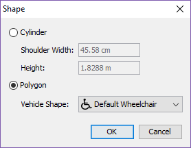
Preparing occupants who can become assistants can be done as follows:
Any number of assisted evacuation teams may be created. Assistants join teams through their behaviors and clients ask for assistance from teams through their behaviors. By default, assistants join the default team.
Assistants may only be a member of one team at a time, but they may be a member of several teams during the course of the simulation. This is accomplished by using an Assist Occupants action for each team in the assistant’s behavior.
To edit assisted evacuation teams, on the Model menu, click Edit Assisted Evacuation Teams (see Figure 138)
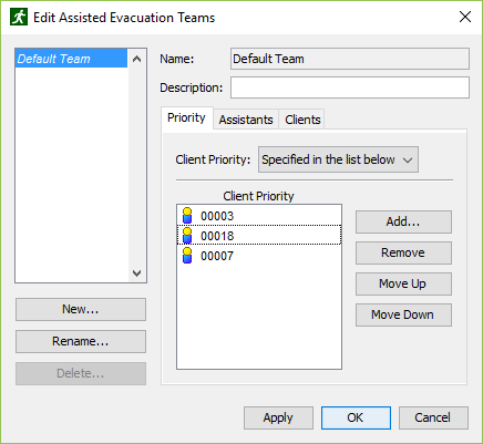
On the Priority tab, Client Priority controls the order in which clients are evacuated by a team.
The priority can be specified as follows:
The Assistants tab is read-only and shows all assistants who currently have a behavior that joins the team with an Assist Occupants action at some point in the simulation. You must use an Assist Occupants action to add an assistant to this list.
The Clients tab is read-only and shows all clients who currently have a behavior that requests assistance from the team with a Wait for Assistance action at some point in the simulation. You must use a Wait for Assistance action to add a client to this list.
Movement groups are used to keep occupants together during the simulation. This feature can be used to explicitly link occupants present at the start of the simulation and can also be used with occupant sources to link occupants inserted during the simulation. The first case might be used in a simulation that begins with families already seated together in a theater and the second might be used to simulate group arrivals via railway car.
Occupants that are part of a group remain grouped during the entire simulation - there is no facility for leaving and joining groups. In addition, to be members of the same group, occupants must use the same behavior.
While occupant movement groups can be used to create simulations that have the appearance of more realistic behavior, specific data about grouping is generally unavailable in validation studies and the relationship between movement times and specific grouping parameters is unknown. Because grouping adds constraints and never increases the individual movement speed of an occupant, it should generally produce more conservative (i.e. slower) simulation times than the ungrouped equivalent. However, if using groups in an evacuation simulation, it is highly recommended to run the simulation both with and without grouped occupants to identify the impact of occupant groupings on evacuation times.
For output associated with grouped movement, see Groups Output.
Grouped movement is controlled by two concepts: connected state and the group leader. If a group is in a "disconnected" state, occupants will walk toward the leader. If a group is in a "connected" state, occupants move toward the goal dictated by their behavior. This framework allows groups that have become broken up to re-form and avoids imposing to harsh movement restrictions related to divided doors and other minor navigational differences.
The details of these behaviors are controlled by the following four parameters:
Smaller values for Maximum Distance and Slowdown Time give more cohesive groups and larger values give looser groups.
Group members share component restrictions (see Movement Tab). If a component is restricted for some group member, other group members will avoid the component as well.
Movement Groups represent groupings of specific occupants that exist at the start of the simulation. They are listed in the Tree view within the Movement Groups node. They also appear in the property panel when selecting occupants belonging to the same Movement Group. Clicking the name of a Movement Group in the property panel will select it in the Tree view.
To create a Movement Group:
The new Movement Group will appear in the Tree view within the Movement Groups node. The Movement Group parameters (e.g. Maximum Distance) can be edited by selecting the Movement Group in the tree.
Manually creating individual Movement Groups is likely only necessary for special cases. Movement Group Templates offer a way to automatically create Movement Groups.
Rather than describing a specific set of occupants that will move together, Movement Group Templates describe a kind of Movement Group. An example might be "Families, with 1-2 adults and 1-3 children". Pathfinder can use these descriptions to automatically create large numbers of Movement Groups from selections of occupants or during the simulation.
In addition to the three movement parameters described earlier, Movement Group Templates require occupant profile-based creation parameters:
To create a Movement Group Template:
The new template will be added to the Tree view in the Movement Group Templates node. The created template can now be used to automatically create movement groups.
When Pathfinder uses Movement Group Templates to sort occupants into movement groups, the algorithm is controlled by the following parameters:
To create Movement Groups using a template:
The new movement groups will be added to the Navigation view in the Movement Groups node and the parameters of individual groups can be edited if required.
When using the New Movement Group(s) from Template action, it is important to note that occupant profiles will be reset by the operation.
Sources insert occupants into the model while the simulation is running. By default, sources do not use groupings when adding occupants. Movement Group Templates can also be used to create movement groups dynamically as occupants are added to the simulation from sources. Sources can create grouped occupants using the following parameter:
To configure an occupant source to add grouped occupants:
The source will now insert grouped occupants based on the template settings.
An Occupant Target represents a location on the navigation mesh that can be occupied by a single occupant at a time. Occupants obtain a reservation to a target using a reservation system and can occupy a target for any amount of time. They can even keep a reservation for a target when they are not occupying it, preventing others from using it.
Occupant Targets are useful in a variety of scenarios, including ingress, general movement, and evacuation. For ingress, targets can represent seating, where occupants reserve a seat, move toward it, and then wait for an indefinite amount of time. Similarly, in general movement the targets can also represent seating, but occupants can occupy a seat for a limited time before giving it up for another occupant to fill, such as in a food court or airport terminal waiting area. Targets can also be useful in evacuation, including representing planned refuge locations for assisted evacuation or defining locations at which individuals must perform some action prior to evacuating.
Targets are represented as circular areas on the navigation mesh with a line extending from the center, representing their orientation as shown below.
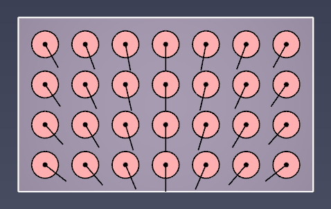
There are two main methods for creating Occupant Targets. Individual targets can be placed using the Occupant Target tool. Alternately, multiple targets can be created from existing occupants.
To create an Occupant Target using the Occupant Target tool, perform the following steps:
There are currently no tools to directly add multiple Occupant Targets to the model, but targets can be created from existing occupants. This indirectly allows existing occupant placement tools to also be used to create Occupant Targets.
To create multiple targets in this manner, perform the following:
A dialog will appear asking whether to delete the selected occupants. Choosing Yes will delete them, effectively converting them into Occupant Targets. Choosing No will leave the selected occupants as-is, creating Occupant Targets at their locations.
The resulting Occupant Targets' orientations will match the initial orientations of the selected occupants.
When an Occupant Target is selected, the following properties can be edited in the property panel:
The orientation of an Occupant Target can be edited directly by selecting the target and editing the Orientation property in the property panel. The orientation can also be adjusted by manipulating the orientation handle in the 2D/3D view (see Occupant Target Handles).
Both of the above methods may be time-consuming for models with many Occupant Targets. A faster approach is to orient the handles of multiple targets at once, which can be accomplished in two different ways. Targets can either be oriented so they all face a reference point or they can be randomized.
To orient the targets toward a reference point, perform the following:
All selected targets will now be oriented so that they face the specified reference point. The images below demonstrate some orientations generated using this action.
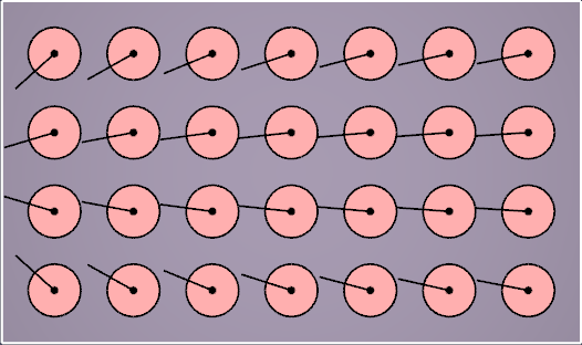 | 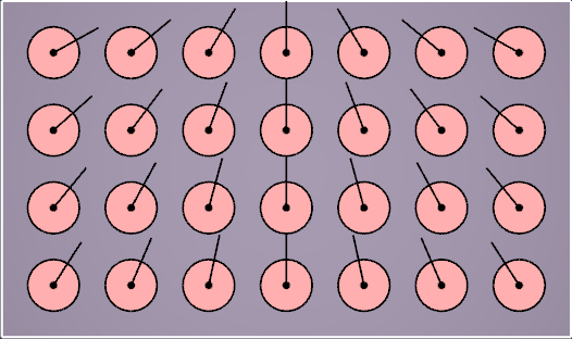 |
If a more disorderly arrangement is preferred, Occupant Target orientations can also be randomized as follows:
This can be repeated to generate different arrangements.
Each Occupant Target has an associated priority that can optionally be used by an occupant’s behavior to help the occupant determine which targets they prefer. The priority of an Occupant Target can be edited directly by selecting the target and editing the Priority property in the property panel.
The priorities of multiple Occupant Targets can also be generated based on a distance gradient from a reference point. For instance, with stadium seating this might be used to generate priorities so that occupants fill seats from the middle of a row outward. Alternately, seats might be prioritized such that those closest to a focus point have highest priority.
In order to generate priorities in this manner, perform the following:
The following distribution parameters control how the priorities are generated for the selected targets:
Occupant Target priorities can optionally be visualized using a colormap. To do so, on the View menu, select Color Occupant Targets→By Priority. The images below demonstrate coloring by priority with two different priority distributions. Dark red targets are high priority, and dark blue are low priority.
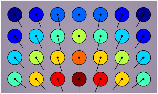 | 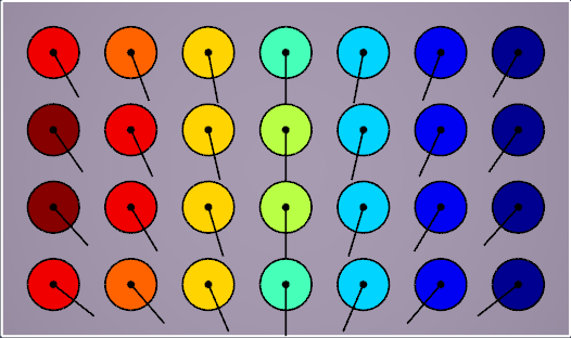 |
In order for an occupant to reserve and navigate toward an Occupant Target, their behavior must have a Goto Occupant Targets action, as described in The Goto Occupant Targets Action. When an occupant starts this action, they will reserve a target using the reservation system as described below. If they successfully reserve a target, which requires them to successfully plot a path toward a target and be chosen by the system, they will navigate toward the target.
Once an occupant has reserved a target, the occupant will keep the reservation until the next Abandon Occupant Targets action in the behavior list. This prevents other occupants from reserving the target, even if the owning occupant leaves the target to perform a Trigger behavior. When using a Trigger, the occupant will only abandon their reserved target if the Trigger behavior contains an Abandon Occupant Targets action.
The Goto Occupant Targets action does not by itself cause an occupant to wait at the target. In order to do so, in the occupant’s behavior list, add one of the wait actions after the Goto Occupant Targets action. The wait action will cause the occupant to wait at their most recently reserved Occupant Target. It also uses the reservation system and the previous Goto Occupant Targets action’s properties to ensure the occupant maintains a reservation to one of the previously specified targets.
For instance, if an occupant is waiting at an occupant target and is then distracted by a Trigger whose behavior includes an Abandon Occupant Targets action, the occupant may no longer have a reserved target when they finish their Trigger behavior. The occupant will then use the reservation system again to reserve a new target from the set of targets chosen in the most recent Goto Occupant Targets action.
Whenever an occupant starts a Goto Occupant Targets action or is using one of the wait actions that follows a Goto Occupant Targets action, the occupant will use the Occupant Target reservation system.
The reservation system operates in multiple steps, possibly over the span of multiple simulation time steps. In general, the reservation system works as follows:
When choosing which Occupant Targets to request, an occupant will proceed as follows:
When picking from a set of targets, the occupant will use the preferences to further reduce the target set as follows:
Higher or Lower, the target set will be reduced to those with the same highest or lowest priority, respectively.
Otherwise, the target set is left as is.None, the occupant will pick at random.
If the preference is instead set to Nearest, the occupant will pick the target nearest to them.In some models there may be many conflicting reservation requests. For instance, suppose a model is seeded with thousands of occupants who want to go to Occupant Targets. Also suppose there are thousands of Occupant Targets, each with a different priority (see Prioritizing Occupant Targets) and that the occupants all desire the targets with highest priority. In this case, all occupants will immediately request the highest priority target. The reservation system can only pick one winner, while all others have to choose another target. In the next timestep, the occupants who did not win will choose the next highest priority target, repeating until all occupants have a reservation or until there are no more targets left.
If occupants were only allowed to request one target in each timestep, it could take thousands of timesteps to resolve the conflicts. To alleviate this problem, if an occupant sees that there were conflicts in the previous timestep for one of their requested targets, they may make several requests in the current timestep. The number of requests they choose in each time step depends on the number of conflicts in the previous timestep as well as the Occupant Target Resolve Time simulation parameter, as discussed in Miscellaneous Parameters. Using this parameter, occupants are guaranteed to reserve all available occupant targets within this time limit plus two additional timesteps from the time they start reserving targets.
For instance, suppose Occupant Target Resolve Time is set to the default time of 5 s.
If the occupants start a Goto Occupant Targets action at t=0, either all targets should be reserved or all occupants should have a reservation by t=5.05 s, using the default timestep of .025 s.
There are currently some limitations for occupants when using Occupant Targets:
See Results for more information on the output available for Occupant Targets.
Pathfinder Triggers are objects that can interrupt an occupant’s current behavior and replace it with another behavior, either temporarily or permanently. Triggers can be global or they can have some area of influence, such as a circlular area or an entire room. In either case, they can be stationary or can move with an occupant. They can also be placed manually before running the simulation or can be created during the simulation by an occupant as part of their behavior. Occupants can be forced to use triggers or can use them based on a probability distribution.
The following are some common use-cases for triggers:
Once an occupant uses a trigger, they will not use it again for the duration of the simulation.
As mentioned previously, triggers can either be placed manually prior to starting the simulation or they can be created by an occupant as part of their behavior.
Placing triggers manually can be helpful for creating global alarms or stationary distractions, such as signs. To add a trigger in this way, perform the following steps:
Line of Sight or Same Room, or the Behavior is set to Wait at Trigger, enter a location for the trigger.
This can be done by either clicking a location in the 2D/3D View or by typing in a Location in the property panel.
If the Awareness is set to Line of Sight, click+drag the left mouse button to set a location and control the Awareness Radius.In the Navigation View, the created triggers can be found under the Triggers→Placed Triggers group.
In order for a trigger to be created during the simulation, a Trigger Template will first need to be defined prior to running the simulation. Then, an occupant can create a Trigger Instance from a Trigger Template as part of their behavior with the Create Trigger action. Trigger templates share the same Trigger Properties as placed triggers except for location. They do not influence occupant behavior until created by a behavior action.
To create a trigger template, perform the following steps:
Trigger Templates in the Navigation View, and choose New Trigger Template.In the Navigation View, trigger templates are found under the Triggers→Trigger Templates group.
Trigger Templates can also be created using the properties of an existing placed trigger.
To copy a placed trigger’s properties into a trigger template, perform the following steps:
A new trigger template will be created based on each trigger selected. After creation, these templates are disconnected from the original triggers and the properties of both can be edited seperately.
Triggers can change an occupant’s behavior to a simple built-in behavior that waits at the trigger for a limited time, or it can change the behavior to any other defined in the model. The occupant’s behavior can be changed permanently if the trigger behavior ends with a terminal action, such as Goto Exits. Alternatively, the trigger can temporarily interrupt the occupant’s current action if the trigger behavior ends with a Resume Prior Behavior action. In this mode, the behavior action that was interrupted by the temporary trigger behavior will be resumed when the trigger behavior is completed. For instance, if the occupant is using a Goto Rooms action and is interrupted by a trigger before they reach one of the rooms, the occupant will perform the trigger behavior and then resume the Goto Rooms action when the trigger behavior is complete.
To use the built-in behavior that waits at the trigger, perform the following:
<Wait at Trigger>.To define a custom behavior for the trigger, create the behavior as defined in Behaviors and select it as the trigger’s Behavior.
Because a trigger can only define one behavior, all occupants who choose to use the trigger will use the same behavior. If you need the occupants to use different behaviors, however, you can do one of the following:
The Wait and Wait Until actions operate in a specific way when interrupted by a temporary trigger.
When either of these actions is started by an occupant, an ending time is calculated and never changes, even if interrupted.
For instance, if an occupant starts a Wait action at t=63 s, and they decide to wait for 30 s, the calculated end time is t=93 s.
If the occupant is interrupted by a temporary trigger while waiting, they will complete the trigger behavior and then resume the wait action.
When they resume the wait action, however, the end wait time remains unchanged at t=93 s.
If the current time is already past t=93 s, the occupant will immediately begin their next behavior action.
Otherwise, they will wait until t=93 s before beginning the next action as usual.
In addition, whenever an occupant is interrupted by a temporary trigger while waiting, the occupant will return to their previous waiting area when they resume the wait action. For instance, if an occupant is directed to go to a room using a Goto Rooms action and then told to wait for some time, their waiting area will be the entire room they reached before waiting. If they are then interrupted by a temporary trigger while waiting, they will return to the waiting room when done with the trigger behavior. Similarly, if they had gone to a waypoint instead, they would return to the waypoint. When the occupant resumes the wait action, the time it takes to get back to the waiting area counts against the wait time. So if the wait time elapses while they are on their way back to the waiting area, the occupant will stop travelling to the wait area and begin their next behavior action.
There are multiple mechanisms that interact with each other in order for an occupant to become aware of a trigger and then ultimately decide to use it (i.e. interrupt their behavior with the trigger’s behavior). This occurs in several stages as detailed below:
Before an occupant can become aware of a trigger, they must first recognize that the trigger exists. This is controlled in two ways:
In order for an occupant to consider an trigger, both of the above properties must hold. A trigger must be in the Allowed Triggers for the occupant, and the occupant must pass the trigger’s Allowed Occupants test.
For each trigger that passes the trigger filtering test as outlined above, the occupant must become aware of the trigger before they will decide to use it. This is determined by both the trigger’s Awareness and Awareness Requirements properties. There are several awareness tests and requirements that can be applied to a trigger as outlined in Trigger Properties.
Once the occupant becomes aware of a trigger, they will schedule a time at which they will decide whether to use the trigger. The trigger’s Decision Time property defines when the occupant will make a decision. The decision time can be a delay after the occupant becomes aware, can be scheduled at a specific time, or can be calculated automatically (see Trigger Properties).
If a trigger’s Decision Time is set to Automatic, the time is calculated based on the occupant’s current movement state.
seeking, they will decide immediately.idling (e.g. using a wait action), the Decision Time will be a random time during their wait period.
If they do not know how long they will be waiting, such as when using the Wait Until Simulation End action, they will use the Default Trigger Idle Time property as their wait period.
This property is defined in the Simulation Properties dialog under the Miscellaneous Parameters tab.Once the Decision Time has elapsed, the occupant will decide whether to use the trigger. If they are still within the Awareness region or the trigger’s Remain aware property is checked, the occupant will calculate a probability of using the trigger (they will ignore the trigger, otherwise).
checked, the probability is exactly the trigger’s Influence.unchecked, the probability is the product of the trigger’s Influence and the occupant’s Trigger Susceptibility (see Trigger Properties and Profile Movement).A probability of 0% means that the occupant is guaranteed to not use the trigger, whereas a probability of 100% or greater means that the occupant is guaranteed to use the trigger.
Values between are used as follows:
0 ≤ random_number < 100.The effect of this can be thought of in two ways:
P, approximately P% of the occupants will use the trigger.P% of the occurances.Once an occupant uses a trigger, they will not use it again for the duration of the simulation. Note that this only applies to a placed trigger or a trigger instance (one created by an occupant from a trigger template). An occupant can still use multiple trigger instances created from a single trigger template (see Creating Triggers).
In addition, if an occupant decides not to use a trigger, the occupant will remember this decision. They will only reconsider the trigger in the future if at least one of the following occurs:
checked and the occupant leaves the trigger’s Awareness region.Global trigger (i.e. its Awareness is set to Global), the occupant finishes a behavior action, and the occupant is not currently using any trigger.
This allows occupants to periodically consider global triggers, even if they previously decided not to use one.Each trigger has a Rank, which is simply an integer value that serves two purposes:
TriggerA with rank 0, and the occupant becomes aware of and decides to use TriggerB with rank 1, then TriggerA’s behavior will be interrupted by TriggerB’s behavior.
If TriggerB’s behavior ends with a Resume Prior Behavior action, and TriggerA’s Resume if interrupted property is checked, then TriggerA’s behavior will resume.
Otherwise, the remainder of TriggerA’s behavior will be skipped, and the occupant’s original behavior will be resumed instead.The following properties can be set for a trigger in the property panel, either during creation or when a trigger is selected:
<Wait at Trigger>, allows for a simple definition of a behavior, where an occupant will seek to a trigger’s location and then wait there for a specified amount of time.
If the trigger is moving, an occupant will seek to it once and then wait at that location. The trigger may move away during this wait.
If the trigger is unreachable, the occupant will wait until it becomes reachable again.
When using this value, you do not have to create a separate behavior (see Trigger Behavior).<Wait at Trigger>, Wait Area Radius defines the waiting area, separate from the awareness area (defined by Awareness Radius).
This is the same as setting an Arrival Radius when specifing a Goto Waypoint action (see Trigger Behavior).<Wait at Trigger>, this defines the amount of time an occupant will wait at the trigger before resuming their behavior prior to using the trigger (see Trigger Behavior).The occupant always knows about the trigger from anywhere in the model.
Defines additional requirements that must all be met before an occupant starts the Decision Time timer.
The minimum amount of time an occupant must be aware of the trigger or its template. This is similar to the Min. Awareness Count, but the occupant accumulates a time counter while it’s aware of the trigger.
unchecked, this value is multiplied by the occupant’s susceptibility to triggers to define the probability.
See the Profile Movement tab for more information about defining the occupant’s susceptibility.
While this value is presented as a percentage, the value can actually be greater than 100% to give a strong preference for the trigger.
Likewise, it can be set to 0% to effectively disable the trigger (see Trigger Decision).If checked, indicates that an occupant’s Trigger Susceptibility should be ignored when calculating the probability that an occupant will use the trigger.
In this case, the trigger Influence alone controls the probability.
This may be useful, for instance, if you want to ensure that occupants will use the trigger, such as a trigger for a global alarm, as long as the trigger is in the occupant’s Allowed Triggers list.
If unchecked, the trigger Influence is multiplied by the occupant’s Trigger Susceptibility to determine the probability of using the trigger.
See Profile Movement and Trigger Decision for more information.
While triggers work with most behaviors and for most occupants, there are some limitations, including the following:
See Results for more information on the output available for triggers.
At any time, the state of the perspective camera can be saved, including its position, orientation, and zoom. This information is stored in an object called a View. A view can be recalled later in either Pathfinder or the 3D Results to view the scene from that perspective.
Views appear in Pathfinder as points and can be hidden either individually or as a whole.
To show/hide all views, click the Show View Objects button ![]() in the 3D/2D view toolbar.
in the 3D/2D view toolbar.
To create a view, follow these steps:
A new view will appear in the Navigation View as shown in Figure 144.
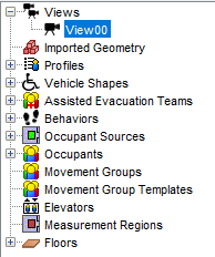
To recall a view, perform any of the following:
This will show the 3D View and the perspective camera will be initialized with the state of the saved view.
If the orientation of a view needs to be changed, perform the following:
Alternatively, the graphical representation of the camera can be manipulated to move the location of the view as discussed in Manipulating Objects with Handles.
In order for the views created in Pathfinder to be available in the Results, a special views file is written to the output folder whenever the simulation is run. When the Results application is opened, it then reads the views from this file and makes them available in the Results.
Because this file is only automatically written when the simulation is run, however, a view can be changed in Pathfinder after running the simulation, making it out of sync with the views in the Results. In order to synchronize the views in Pathfinder and the Results without re-running the simulation, the views file must be manually written. To do so, follow these steps:
In previous versions of Pathfinder, tours could also be created inside Pathfinder. This functionality was later moved to the 3D Results. Tours made in previous versions of Pathfinder, however, will still appear in the Navigation View of Pathfinder. While they can no longer be edited within Pathfinder, they can still be deleted. Ones that are not deleted will be written to the Results views file so that they are available in the Results.
Scenarios can be used to manage variations of a single model. Each scenario consists of a set of properties which are customized in that scenario. Switching between scenarios will update properties of objects to their values in that scenario.
When running a simulation, you may simulate multiple scenarios. This creates multiple results output files from one Pathfinder input file.
To create a scenario, you can use the Edit Scenarios dialog (Figure 145).
To open the Edit Scenarios dialog: on the Model menu, click Edit Scenarios, or click the scenarios button ![]() in the toolbar.
in the toolbar.
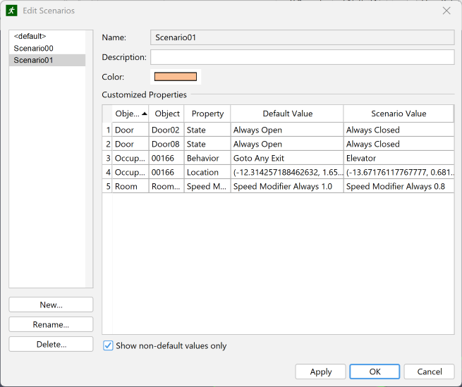
Alternatively, you may create a scenario by selecting <Add New> in the Active Scenario selection box (Figure 146) in the toolbar.
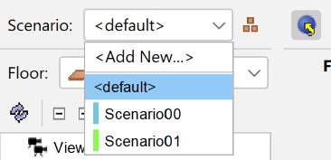
From the Edit Scenarios dialog, you may edit the following properties of a scenario:
The dialog also shows a table of all properties customized by the scenario. Editing these properties, however, is done outside of the dialog. A "Show non-default values only" checkbox below this table allows you to toggle the visibility of non-default values to easily view relevant changes.
Most objects in Pathfinder have properties which can be customized in scenarios.
To customize properties of selected objects in the Property Panel,
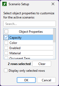
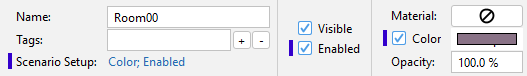
Properties that are edited in dialogs, such as profile properties and global simulation parameters, can also be customized by scenarios.
To customize properties in a dialog,
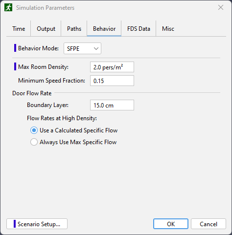
Running scenarios is covered in Starting and Managing Simulations.
Most objects can be edited in two ways in Pathfinder. One way is to transform the object, including rotating, translating (moving), and mirroring it. Another way is to graphically manipulate the objects by dragging handles. Objects can also be copied either with copy/paste or through the transform tools as discussed in the following section.
All geometric objects can be transformed and/or copied. All transform/copy options are available through tools in the 3D and 2D views. The following transforms are available and are discussed in the following sections: moving, rotating, and mirroring.
To move one or more objects, select the objects and click the move tool ![]() from the 2D or 3D view.
The property panel for the move tool is shown in Figure 150.
from the 2D or 3D view.
The property panel for the move tool is shown in Figure 150.
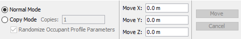
The object can be moved either manually or graphically:
Objects can also be copied using the move tool. To do so, select the move tool, select Copy Mode from the property panel, and follow the same steps as above for moving an object. Alternatively, hold CTRL on the keyboard while defining the offset. This will create a copy of the object that has been offset by the move distance.
Similarly, an array of objects can be made by specifying a value greater than 1 for the Copies field in the property panel. The array is created by offsetting each previous copy by the move distance. If, when copying rooms, the resulting copies overlap one another the most recent copies take precedence over earlier ones, meaning that earlier ones will have area subtracted from them.
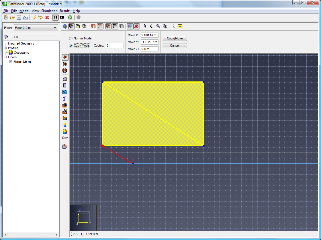 | 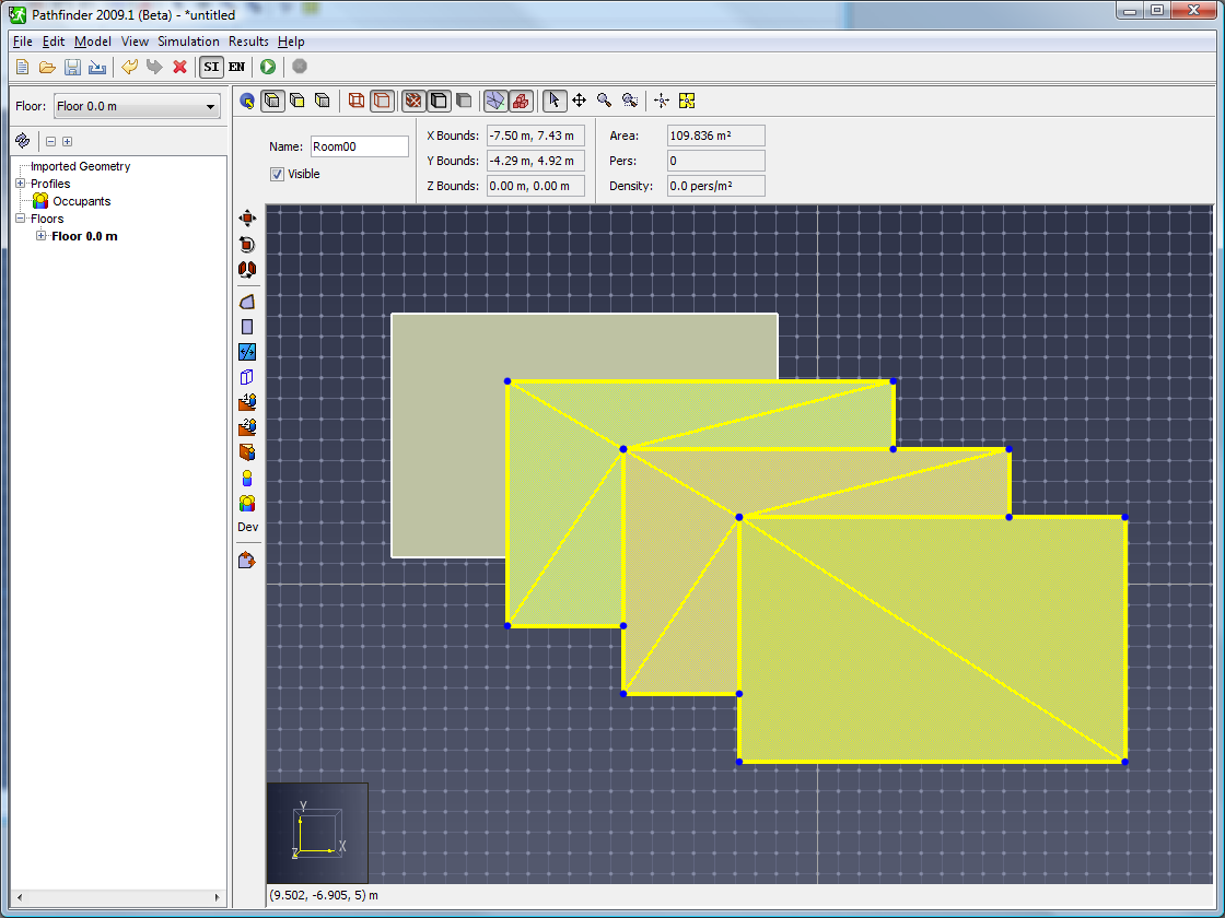 |
To rotate one or more objects, select the objects and click the rotate tool ![]() from the 2D or 3D view.
The property panel for the rotate tool is shown in Figure 153.
from the 2D or 3D view.
The property panel for the rotate tool is shown in Figure 153.
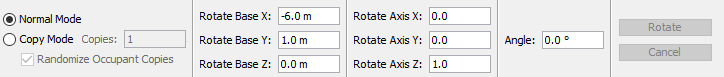
The object can be rotated either manually or graphically:
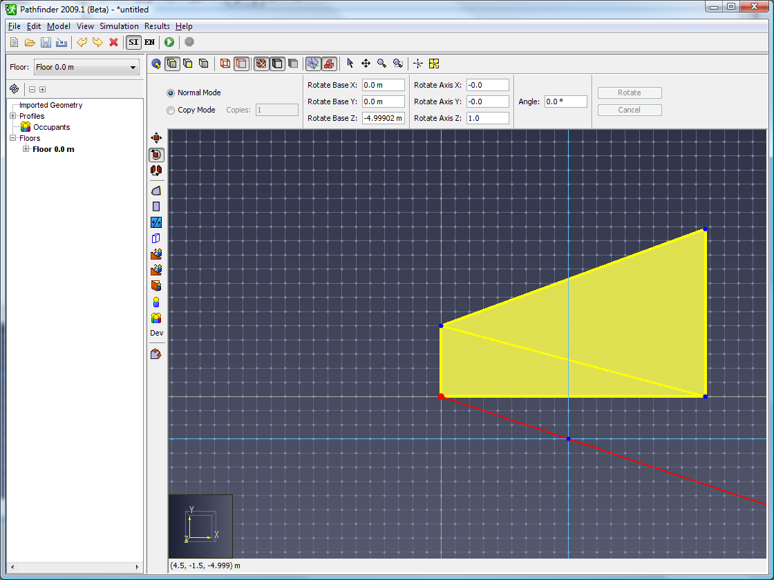 |  | 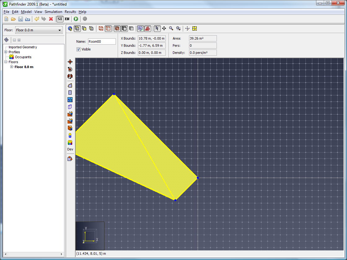 |
Objects can also be copied using the rotate tool.
This will create a copy of the object that has been rotated from the original using the rotate parameters. Similarly, an array of objects can be made by specifying a value greater than 1 for the Copies field in the property panel. The array is created by rotating each previous copy by the rotate angle.
If copying rooms and resulting copies overlap one another the most recent copies take precedence over earlier ones, meaning that earlier ones will have area subtracted from them. An array is shown in Figure 158.
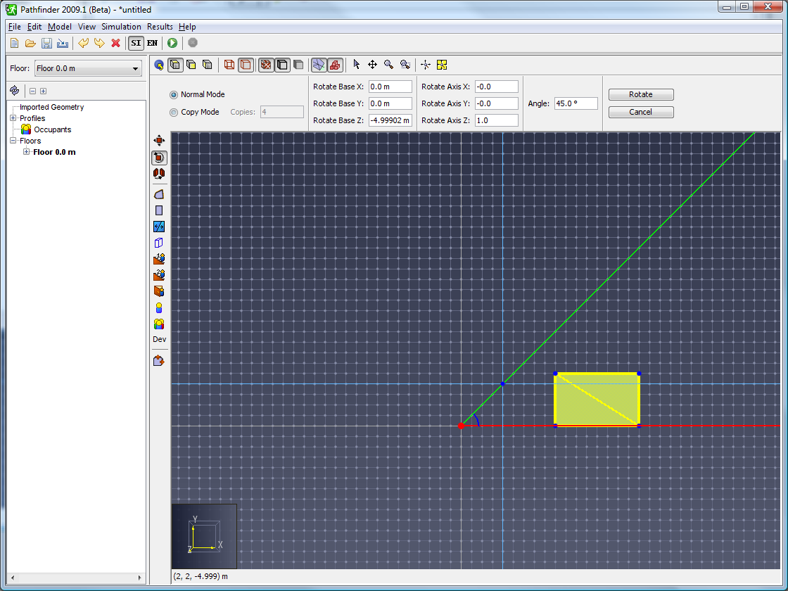 | 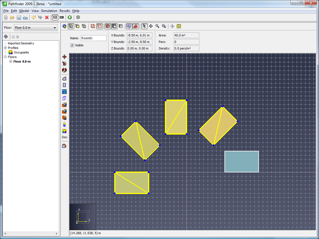 |
To mirror one or more objects about a plane, select the objects and click the mirror tool ![]() from the 2D or 3D view.
The property panel for the mirror tool is shown in Figure 159.
from the 2D or 3D view.
The property panel for the mirror tool is shown in Figure 159.
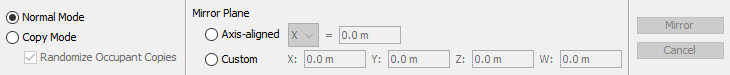
The object can be mirrored either manually or graphically:
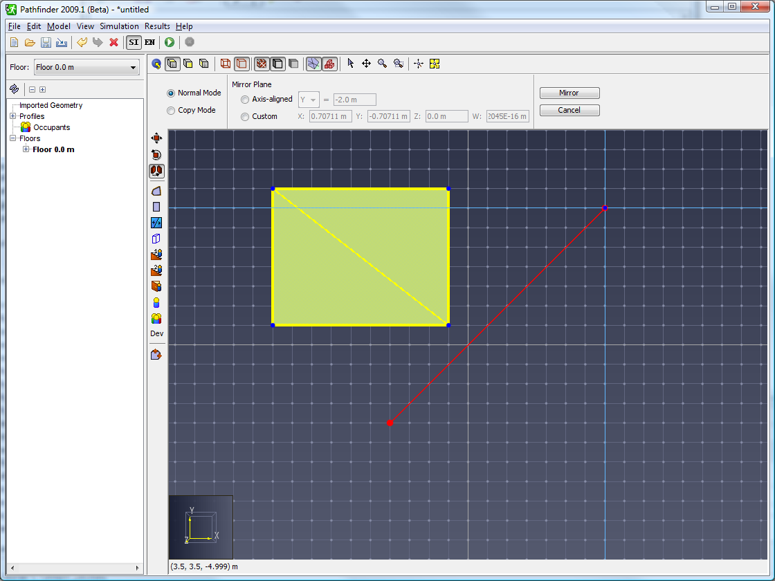 | 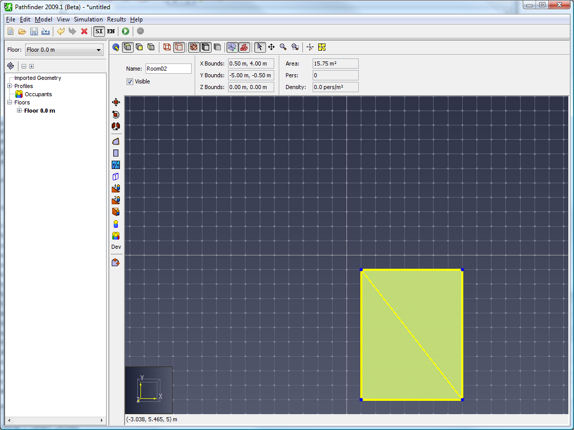 |
Objects can also be copied using the mirror tool. To do so, select the mirror tool, select Copy Mode from the property panel, and follow the same steps as above for mirroring an object. Alternatively, hold CTRL on the keyboard while defining the mirror plane. This will create a copy of the object that has been mirrored from the original using the mirror plane.
Some objects, including occupants, rooms, stairs, and doors, can be edited through manipulator handles. Handles act as points on an object that can either be dragged with the selection tool or edited by the keyboard to edit the attached object. Handles only appear if a single object is selected and show as blue dots as shown in Figure 162.
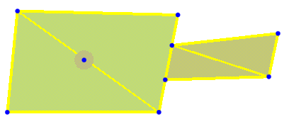
To select an object’s handle, the object itself must first be selected.
Once it is selected, the blue handles should appear.
Next select the Select/Edit tool ![]() .
Now an individual handle can be selected by clicking it, which will make the handle property panel appear as shown in Figure 163.
To deselect the handle, press ESC on the keyboard, click anywhere else in the model, or select another object.
.
Now an individual handle can be selected by clicking it, which will make the handle property panel appear as shown in Figure 163.
To deselect the handle, press ESC on the keyboard, click anywhere else in the model, or select another object.
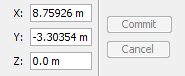
A handle can be edited in one of two ways: it can be edited with the keyboard to enter precise values or it can be edited graphically.
When rooms are selected, a handle can be found at every vertex on the boundary of the room. The handles move the underlying vertex to reshape the room. The handles can be moved to any location within the plane of the face the vertex is on. If the vertex is shared between two faces in non-parallel planes, the handle can only be moved along the edge to which it is attached.
When a thin door is selected, three handles will be displayed as shown in Figure 164. The handles on the ends of the door allow the door to be moved along the edge to which it is attached. The middle handle allows the door to be made thick by moving the handle to the edge of another room as shown in Figure 165.
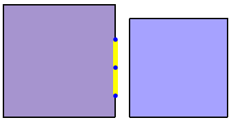 |  |
When a thick door is selected, six handles will be displayed as shown in Figure 165. The four handles on the corners of the door allow the door to be moved along the edge to which each handle is attached. Each middle handle allows the door to be made into a thin door by dragging to the other middle handle. The middle handle can also be useful to reattach the door to a room if the door somehow became detached (such as by a modification to the room).
When a stair or ramp is selected, six handles will be displayed as shown in Figure 166. The four corner handles each allow the stair/ramp to be moved along the edge to which the handle is attached. The middle handles allow the stair/ramp to be reconnected to another room. The middle handles can also be useful if the geometry of one room attached to a stair/ramp has changed in such a way that the stair/ramp is no longer attached to the room. The middle handle can be used in this case to reconnect to the room.
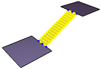
When an occupant is selected, there is only one handle as shown in Figure 167. The sole purpose of this handle is to move the agent to another location. Moving an agent in this manner has a benefit over the translation tool in that the location automatically snaps to an existing room or stair as when adding an agent using the occupant dropper tool.
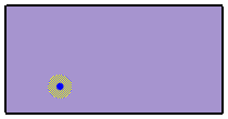
When a waypoint is selected, two handles are displayed as shown in Figure 168. The center handle allows the waypoint to be moved to another location similarly to the occupant handle. The perimeter of the circle can be used as a handle to change the arrival radius of the waypoint.
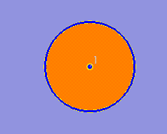
When an Occupant Target is selected, two handles are displayed in Figure 169. The center handle allows the target to be moved to another location. The line handle extending from the center can be used to change the orientation of the target. The orientation defines the direction the occupant will face when waiting at the target.
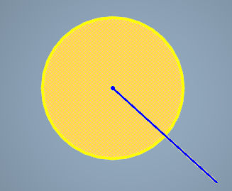
Several objects in Pathfinder can be enabled or disabled. Disabling an object removes the object from the model. A disabled object does not appear in the simulation. Following objects can be enabled and disabled in Pathfinder:
To enable or disable an object, right click on the object in the 3D view or in the navigation tree and select Enable or Disable. Disabled objects are invisible in the 3D view. In the navigation tree, disabled objects are greyed out and crossed out.
Large models can contain thousands of occupants and geometry components. Pathfinder provides a variety of utilities to assist in organizing and reorganizing complex models to maintain the proper associations between objects.
While it is simple to select an individual object from either the Navigation view or the Model view, doing so for every single object to edit can be cumbersome. The following actions are available from the right-click menu to accelerate selecting networks of objects.
Most models can have complex relationships between objects, with some objects referencing others. In these cases, it can often be helpful to start at the referenced object and see which objects are referencing it. To do this, right-click the referenced object and choose Show Referencing Objects.
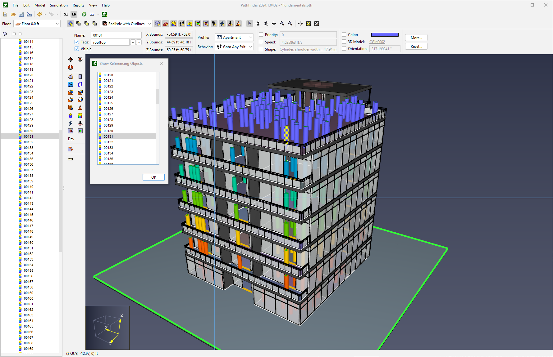
This opens the floating Show Referencing Objects dialog, which displays each of the referencing objects in a list. Objects in the list have their selection state synchronized with the selection in the Navigation View and the Model View. This includes the ability to right-click an object in this tool and access the object’s context menu.
Any number of custom Tags may be added to identify and organize objects with common characteristics. Most non-group node objects in the Navigation View support tags. Once added, the given Tag will also appear in its own group in the Navigation View.
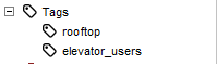
Tags are assigned in the property panel. A Tag will be created for each unique character string separated by spaces or other delimiter characters.
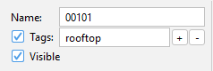
If multiple objects are selected, the Tag editor will display as <mixed>. Editing the Tag field in this state can potentially cause unexpected changes.
To work around this, the Tag editor includes custom buttons for adding or removing Tags in a mixed selection state.
The + button will launch an editor where you may enter the Tags you would like applied to each selected object.
The - button will launch an editor where you may enter the Tags you would like to remove from each selected object.
One of the main purposes of Tags is to quickly find and identify related objects. Pathfinder provides several ways to quickly find tagged objects.
Selects other objects in the model referencing the selected Tag.
Lists the referencing objects in a floating window.
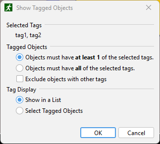
tag1 and tag2, the chosen objects will have either tag1 or tag2 or both tag1 and tag2.tag1 and tag2, the chosen objects will have both of the tags.tag1 and tag2, and an object contains these tags but also contains tag3, it will be excluded from the result.
This may be useful, for instance, to find objects that contain exactly the selected tags and no more.As objects are being created via the drawing tools, geometry import, manager dialogs, and Copy / Paste, the names assigned by Pathfinder can become increasingly complex. After some time it may be desireable to change many thousands of object names to make the model more clear.
To open the Rename dialog, right click one of the selected objects in either the 3D view or in the Navigation view and select Rename….
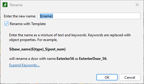
To rename all selected objects with a common name, simply enter the desired new object name in the text field, and click OK.
For more complex renaming scenarios, you may check the Rename with Template checkbox.
When the Rename with Template checkbox is selected, you may create a name as a mixture of both text and keywords. Keywords are uniquely interpreted for each of the selected objects based on the object’s properties. Using this approach a large set of mixed-type objects can all be renamed according to a standard syntax.
For example:
*${base_name}${type}_${post_num}
will rename a door called Exterior56 to ExteriorDoor_56.
The full set of available keywords are as follows:
Each of these keywords are detailed in the Rename dialog dropdown.
To make it easier to work with name templates, the keyword names in the dialog work as buttons. Clicking one of the keyword buttons will inject the keyword directly into the editor dialog at the current caret location.
Pathfinder contains some useful tools to analyze various properties of a model.
Measurement regions cause the simulator to output time history data for velocity and density within a specific region on the navigation mesh. See Measurement Regions Data for information about Measurment Region results.
Measurement regions can be created using the Add a Measurement Region tool ![]() .
.
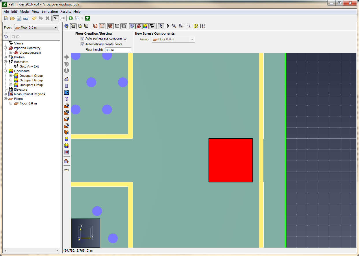
Adding one or more density regions will cause the simulator to output a CSV file named filename_measurement-regions.csv containing data for each density region.
The data in this file can be used to plot fundamental diagrams in the measurement area.
Output frequency for measurement region data is controlled by the Data Output Freq. parameter on the Output tab of the Simulation Parameters dialog.
To ensure accurate results, measurement regions must:
Essentially, measurement regions should be placed on open space that will be used by occupants. Ideally, the measurement region should not be larger than the area where the steady flow under study occurs. If the measurement region is too large, results might indicate a lower value than expected because the quantity is integrated over the entire region.
For additional information about measurement regions, please refer to the Pathfinder Technical Reference.
Distances can be measured by using the measuring tool ![]() .
.
To do so, select the measuring tool from the 3D or 2D view. To measure distance along a sequence of points, left-click each point. After each point in the path has been specified, right-click to display the cumulative point-to-point distance in a dialog box.
When measuring distances in the 3D view, the distance is taken as the actual distance between snapped points. When measuring distances in the 2D view, however, the distance is taken by projecting the points onto a plane parallel to the camera view plane, and then taking the distance.
The Simulation Parameters dialog provides a way to control certain features of the simulation, as well as provide some default values.
The Time tab (Figure 176) provides the following options:
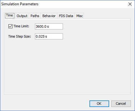
The Output tab (Figure 177) provides the following options:
filename_occupants_detailed.[csv, json], where filename is the name of the saved PTH file without the .pth extension.filename_occupant_id_occname.[csv, json], where filename is the name of the saved PTH file without the .pth extension, id is the integer id of the occupant assigned by the simulator, and occname is the name of the occupant specified in the user interface.+X direction, and they are moving in the +X direction at 1.2 m/s, this column will show 1.2 m/s; however, if they instead move in the +Y direction, this will become 0 m/s because they are not moving toward their goal.
NOTE: This value is always >= 0, even if the occupant is moving backward away from their goal.Controls whether the JSON output files described in Results are generated.
filename_sd_accumulated.csv (see Interpersonal Distance).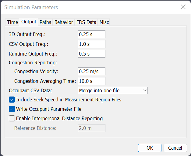
The Paths tab (Figure 178) contains properties that control how occupant paths are generated and how the navigation mesh is triangulated. Generally, these settings should not be changed.
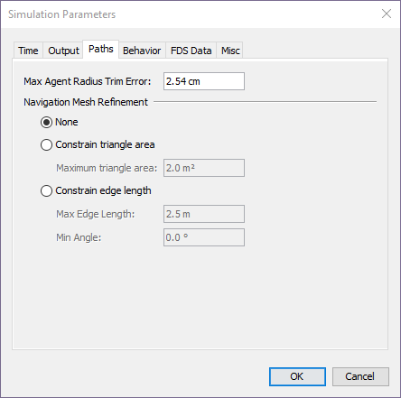
The Behavior tab allows you to set options for Pathfinder’s two primary simulation modes: SFPE and Steering. To select a simulation mode, choose SFPE or Steering from the Behavior Mode drop-down box.
The SFPE mode uses the set of assumptions presented in the Engineering Guide to Human Behavior in Fire (SFPE 2019) and can give answers extremely similar to these hand calculations, depending on selected assumptions. In SFPE simulations, the mechanism that controls simulation movement is the door queue. The SFPE mode uses a simple set of assumptions and usually completes much faster than a comparable steering mode simulation in terms of CPU time.

The SFPE mode supports the following options:
3.6 - 3.8 can cause extremely slow evacuation times.
Using values above 3.8 pers/m2 can cause the simulation to become stuck due to the density dependent velocity calculation.150 mm, a 1.0 m door would be reduced to a 0.7 m opening giving an \(F_\text{s_max}\) of (1.32 pers/s-m * 0.7 m) = 0.924 pers/s.The Steering mode is more dependent on collision avoidance and occupant interaction for the final answer and often gives answers more similar to experimental data than the SFPE mode (i.e. steering mode often reports faster evacuation times). Door queues are not explicitly used in Steering mode, though they do form naturally.
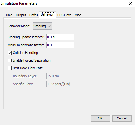
The Steering mode supports the following options:
When enabled, this will cause occupants to attempt to always strictly maintain their Personal Distance (Advanced Tab). When disabled, Personal Distance will only apply while queueing.
The Miscellaneous tab (Figure 181) provides rarely-changed options, including the following:
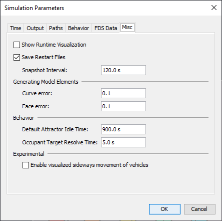
To run a simulation: on the Model menu, click Run Simulation ![]() .
If you have multiple scenarios (Scenarios) defined in your model, you will be prompted to select which ones to run, as shown in Figure 182.
After selecting scenarios, the simulation will begin and the Run Simulation dialog (shown in Figure 183) will appear.
.
If you have multiple scenarios (Scenarios) defined in your model, you will be prompted to select which ones to run, as shown in Figure 182.
After selecting scenarios, the simulation will begin and the Run Simulation dialog (shown in Figure 183) will appear.
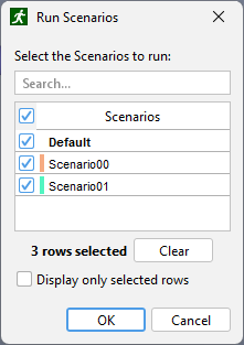
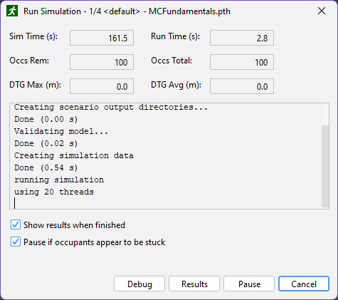
In this dialog, the abbreviation DTG stands for distance to goal. The maximum distance to goal represents distance to goal for the occupant farthest from its goal. The average distance to goal is the average of all occupants' distances to their respective goals.
The title of the dialog shows the currently running scenario, along with how many scenarios were selected to run.
The Debug button launches a runtime visualization that shows the progress of the simulation as it is taking place. This function is different from the Results button which launches the 3D visualization view for simulation results.
A simulation can also be paused, resumed, and cancelled at any time.
Simulations can be run from the command line using the testsim.bat script located in the Pathfinder installation directory.
The following sections detail the two supported use-cases for this script.
To run a single simulation from the command line:
testsim.bat "full_model_path"
Where full_model_path is the full path to the Pathfinder model you wish to run.
This path can be either a PTH model file, or to a TXT input file written by Pathfinder. TXT input files are automatically created by Pathfinder when a model is run, but can be manually created in the user interface by selecting File › Save Simulator Input.
To run all of the simulations in a directory:
testsim.bat "path"
Where path is the path to a directory containing Pathfinder PTH model files. This will run all of the model files in the provided directory, but not in it’s subdirectories.
This will only run PTH model files, and will not run TXT inputs files.
To run all simulations in multiple directories, use the same command as the above with multiple arguments:
testsim.bat "path1" "path2" ... "pathN"
Where each path is a directory containing a Pathfinder .pth model file. As above, this will run all of the model files in the provided directory, but not it’s subdirectories.
When running a simulation, there is the option to pause and resume, but this requires Pathfinder to be running the entire time. Sometimes the need arises to be able to stop a simulation and resume later between Pathfinder sessions, such as if the computer needs to be restarted after installing a system update.
To stop a simulation:
To resume the simulation at a later time:
After running a simulation, several output files will be created. These will be stored in a new folder with the name of your saved PTH file.
If multiple scenarios are defined in the model, a new folder will be created for each scenario’s output.
The summary report file contains information about the simulation geometry, simulation performance, statistics, and usage information for each room, stairway, and door.
Figure 184 shows a portion of an example summary report file.
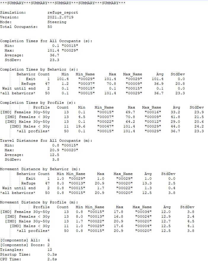
This file is saved in the simulation directory and given the name filename_summary.txt (where filename is the name of your saved PTH file).
To view it, under the Results menu choose Show Summary File.
The first section shows the mode the simulation was run in, the total number of occupants, and statistics on the completion times for the occupants.
It also shows some information about the mesh, including the number of triangles and the doors.
This information can be useful when considering the complexity of a simulation from the standpoint of the simulator.
Each statistic is generated by sampling quantities from the occupants as data points. Only occupants for whom the quantity is relevant are included in the statistic.
Statistics on the following quantities may be printed to the summary file:
The amount of time it takes for an occupant to complete all of their behavior actions. Occupants are not included in this statistic if they fail to complete all their behavior actions. This may happen either because they became stuck or they did not finish their actions before the simulation ending time as specified in the Simulation Parameters dialog.
no triggers line is added.
This statistic is only provided if there are triggers in the model.no occupant targets line is added.no occupant targets line is added.Some statistics are further broken down by behavior and by profile. For occupants who used multiple behaviors and/or profiles due to Change Behavior or Change Profile behavior actions, they are reported according to the behavior or profile in use when they completed their actions.
The table at the end of the summary file gives a listing of each component (doors, rooms, and stairs) in the simulation.
For each component, the FIRST IN column shows the simulation time when the first occupant entered that component.
LAST OUT shows the simulation time when the last occupant exited that component.
The TOTAL USE column shows how many times a component was entered by occupants.
For doors that served more than 1 occupant, the FLOW AVG column shows the result of dividing the total use by the amount of time the room was in use (LAST OUT - FIRST IN).
Each component is annotated with its group names.
For example, "Floor 0.0 m→Rooms→Room00" indicates that "Room00" is in "Floor 0.0 m" in a group called "Rooms".
The filename_out.json file (where filename is the name of your saved PTH file) combines all of the data provided by JSON files described in Results into a single JSON file upon completion of the simulation.
This file is ideal for accessing results data programmatically to do custom post processing in external applications, but is only written if Write Json Output Files is enabled (see Output Parameters).
The Cumulative output file uses the file format shown below.
{
    "triggers": {},
    "doors": {},
    "groups": {},
    "measurementRegions": {},
    "occupants": {
        ...,
        socialDistancing: {
            ...,
            transient: {}
        },
        initialParams: {},
        detailed: {}
    },
    "targets": {},
    "rooms": {}
}
The file provides the following keys:
occupants keys provides quick access to all data relating to individual Occupants.
This key combines data from the Occupant Summary JSON File (Occupant Summary JSON File), Occupant Parameters JSON File (Occupant Parameters JSON File), Occupant History JSON File (Occupant History JSON File), and Interpersonal Distance JSON Files (Interpersonal Distance JSON Files) in to a single JSON object, keyed by Occupant ID.
Accessing the data for a given Occupant ID will yield an object containing all data related to that Occupant.
The object under the Occupant ID uses the format of the Occupant Summary JSON File (Occupant Summary JSON File), however it injects the following 3 new keys:The door history files provide output data for the doors in your model.
The filename_doors.csv file (where filename is the name of your saved PTH file) includes a five-row header, including the column descriptions, names of associated doors, a numeric ID used by Results, quantities, and units. Each row in the represents a single time step, and includes the following columns:
This file is used to display door flow rate, specific flow, and usage history in Pathfinder. The values in this file can also be plotted by right clicking a door in the 3D Results.
The filename_doors.json file provides the same data as the filename_doors.csv file in a different format, shown below, and is only written if Write Json Output Files is enabled (see Output Parameters).
{
    "exited": {
        "time": value,
        ...
    },
    "remaining": {
        "time": value,
        ...
    },
    "doorname [{+/-}{X/Y}]": {
        "usage": {
            "time": value,
            ...
        },
        "queueingDoorUsage": {
            "time": value,
            ...
        },
        "width": {
            "time": value,
            ...
        },
        "boundary": {
            "time": value,
            ...
        }
    },
    ...
}
The JSON file contains the following JSON objects:
Each door object contains the following objects:
To view door flow rate or specific flow, click View Door Flow Rates on the Results menu. This opens a time history plot for doors as in Figure 185. This plot shows data from the door history file.
In the left portion of the window is a list of the doors, and on the right is a graph of the data. For each door, the list on the left shows three rows: one for each of the two directions and one for total. The directional data can be hidden by unchecking Include Directional Data under the View menu. Each row in the list shows group names for each door (if the Include Group Names in Output option under File→Preferences was enabled in Pathfinder when the simulation was run). The group names can be hidden by unchecking Show Group Names under the View menu of the history plot dialog.
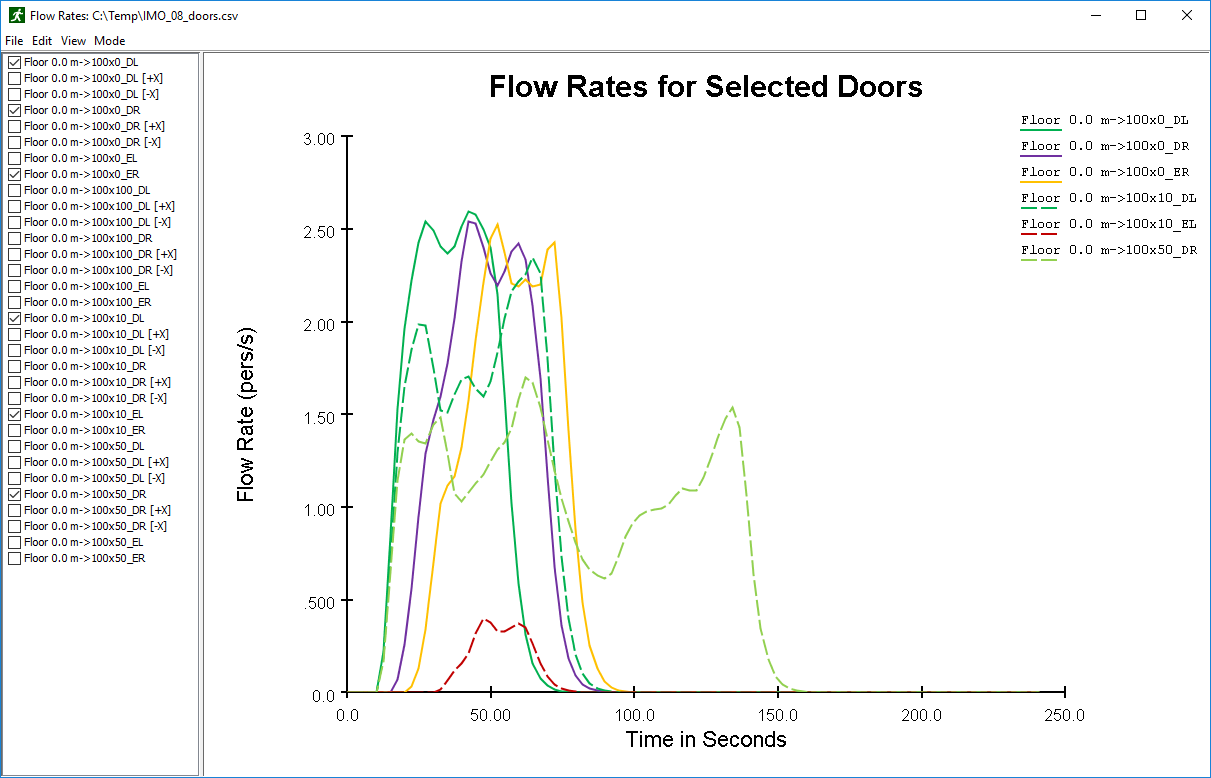
By default, door flow rates are shown. Alternatively, on the Mode menu, choose Specific Flow to view door specific flow.
There are three filtering modes for presenting the flow rate that are selectable through the View menu:
To view door usage, open the Door Flow Rate Rates dialog, and on the Mode menu, select Occupant Counts. This shows the number of occupants that use a particular door in each output time step.
Alternatively, cumulative totals can be viewed by selecting Cumulative Occupant Counts. This shows the total number of occupants to use the door up until that time.
The room history files provide data on occupant usage of the rooms in your model
The filename_rooms.csv file (where filename is the name of your saved PTH file) includes a five-row header, including the column descriptions, names of associated rooms, a numeric ID used by Results, quantities, and units.
Each row after the header represents a different time step. The columns are as follows:
The filename_rooms.json file provides the same data as the filename_rooms.csv file in a different format, shown below, and is only written if Write Json Output Files is enabled (see Output Parameters).
{
    "remaining": {
        "time": value,
        ...
    },
    "exited": {
        "time": value,
        ...
    },
    "roomname": {
        "time": value,
        ...
    },
    ...
}
The JSON file contains the following JSON objects:
To view the room history plot, click View Room Usage on the results menu. Similarly to door history, the list on the left shows group names for each room (if the Include Group Names in Output option under File→Preferences was enabled in Pathfinder when the simulation was run). The group names can be hidden by unchecking Show Group Names under the View menu of the history plot dialog.
The data in this file can also be plotted by right clicking a room in the 3D Results.
The measurement region files provide data for each measurement region in your model.
Each row in the filename_measurement-regions.csv file (where filename is the name of your saved PTH file) represents a single time step, and provides data for each of the following columns:
To display this data as a time history and a speed vs density plot, click View Measurement Regions on the Results menu.
The filename_measurement-regions.json file provides the same data as the filename_measurement-regions.csv file in a different format, shown below, and is only written if Write Json Output Files is enabled (see Output Parameters).
{
    "regionName": {
        "density": {
            "time": value,
            ...
        },
        "velocity": {
            "time": value,
            ...
        },
        "seekVelocity": {
            "time": value,
            ...
        },
        "count": {
            "time": value,
            ...
        }
    },
    ...
}
The JSON file contains the following JSON objects:
Each measurement region object contains the following objects:
To view a speed vs time history graph, click View Measurement Regions on the Results menu, this is the default mode. To view this mode from other alternative modes, on the Mode menu, select Velocity. This shows the speed in the observation region(s) in each output time step.
To view a density vs time history graph, click View Measurement Regions on the Results menu, and on the Mode menu, select Density. This shows the density in the observation region(s) in each output time step.
To view a speed vs density graph, click View Measurement Regions on the Results menu, and on the Mode menu, select Speed vs Density. This shows how a change of density in the observation region(s) affects the speed of movement.
The three filtering modes explained earlier could also be applied to measurement region graphs.
The occupant parameters files provide a summary of the initial states of almost all parameters assigned to occupants in your model.
These files are useful for verifying that real parameter distributions match the distributions specified in the occupant profiles (see Profiles and Stochastic Parameters for more information). These files are written by default but can be turned off in the Simulation Properties dialog (see Output Parameters).
In addition, any occupants that have customized parameters (Customizing Occupants) will invalidate the distributions. These customized occupants must be manually excluded from the analysis to determine resulting distributions.
Each row in the filename_ocupant_params.csv (where filename is the name of your saved PTH file) represents an individual occupant, and provides the initial parameters for each of the following columns:
null if social distancing is disabled for this Occupant.1 if the Occupant will obey one-way restrictions, 0 if they will ignore them. (See Movement Tab > Ignore One-way Door Restrictions)0 if Occupant can move on their own, 1 if they cannot. (Movement Tab > Require Assistance to Move)The filename_occupant_params.json file provides the same data as the filename_occupant_params.csv file in a different format, shown below, and is only written if Write Json Output Files is enabled (see Output Parameters).
{
    "occupantId": {
        "id": value,
        "name": value,
        "startTime": value,
        "profile": value,
        "behavior": value,
        "maxVelocity": value,
        "shape": {
            "type": value,
            "occId": value,
            "radius": value,
            "geometryRadius": value,
            "height": value,
            "center": {
                "x": value,
                "y": value,
                "z": value
            },
            "dir": {
                "x": value,
                "y": value,
                "z": value
            }
        },
        "occupantRadius": {
            "unit": value,
            "data": value
        },
        "geometryRadius": {
            "unit": value,
            "data": value
        },
        "height": {
            "unit": value,
            "data": value
        },
        "room": value,
        "position": {
            "unit": value,
            "x": value,
            "y": value,
            "z": value
        },
        "profileProps": {
            "speedInSmoke": {
                "mode": value,
                "customFuncVisThreshold": {
                    "d_value": value,
                    "d_unit": {
                        "_symbol": value
                    }
                },
                "customFuncVisType": value,
                "customFuncVis": {
                    "x": [value, ...],
                    "y": [value, ...],
                    "extrapolate": value
                }
            },
            "accelTime": {
                "unit": value,
                "data": value
            },
            "minSqueezeFactorConst": value,
            "occModel": value,
            "priorityLevel": value,
            "persistTime": {
                "unit": value,
                "data": value
            },
            "collisionResponseTime": {
                "unit": value,
                "data": value
            },
            "propSpacing": {
                "unit": value,
                "data": value
            },
            "slowFactor": value,
            "boundaryLayer": {
                "unit": value,
                "data": value
            },
            "obeyOnewayDoors": value,
            "escalatorPref": value,
            "localQueueTimeFactor": value,
            "localTravelTimeFactor": value,
            "tailTimeFactor": value,
            "currDoorPref": {
                "unit": value,
                "data": value
            },
            "distTravelledDoubleDist": {
                "unit": value,
                "data": value
            },
            "requiresAssistance": value,
            "initOrient": {
                "unit": value,
                "data": value
            },
            "elevatorWaitTime": {
                "unit": value,
                "data": value
            },
            "attractorSusceptibility": {
                "val": value
            },
            "attractorSusceptibilityIdle": {
                "val": value
            },
            "attractorRestrictions": {},
            "tags": [
                {
                    "name": value,
                    "desc": value,
                    "options": [
                        value,
                        ...
                    ],
                    "d_occCounts": [
                        value,
                        ...
                    ],
                    "d_stats": {
                        id: {
                            "tLastTagged": value,
                            "tLastUntagged": value,
                            "tAccum": value
                        }
                    }
                },
                ...
            ]
        },
  },
  ...
}
The JSON file contains the following JSON objects:
Each Occupant entry contains the following key/value entries:
The interpersonal distance output files provide data related to how closely Occupants are spaced throughout the simulation. Reported distances in these files are measured center-to-center.
Each row in the filename_sd_transient.csv (where filename is the name of your saved PTH file) contains transient data about a single Occupant’s separation from other Occupants at a single CSV output timestep.
Each row lists the closest other occupant and their separation distance.
It also lists the number and ID of Occupants within 1m, 2m, and 3m.
| Column Name | Type | Optional | Description |
|---|---|---|---|
| Time (s) | float | Simulation time | |
| ID | int | Unique ID for occupant | |
| Name | text | x | Occupant name from nav view in UI |
| Group ID | int | x | Unique ID for occupant group, if present |
| Closest Occupant ID | int | x | ID of closest occupant, if present within 3m |
| Closest Occupant Name | text | x | Occupant name from nav view in UI, if present within 3m |
| Closest Occupant Distance (m) | float | x | Distance to closes occupant, if present within 3m |
| Occupants Within 1m (count) | int | Number of occupants within 1 meter | |
| Occupants Within 1m IDs | text | x | Space-separated list of occupant IDs within 1m |
| Occupants Within 2m (count) | int | Number of occupants within 2 meter | |
| Occupants Within 2m IDs | text | x | Space-separated list of occupant IDs within 2m |
| Occupants Within 3m (count) | int | Number of occupants within 3 meter | |
| Occupants Within 3m IDs | text | x | Space-separated list of occupant IDs within 3m |
Each row in the filename_sd_accumulated.csv (where filename is the name of your saved PTH file) contains accumulated exposure data for a single Occupant.
The data includes the ID and total exposure time of the Occupant who spent the longest time within reference distance of the row’s Occupant, and a count and IDs of all Occupants who were within reference distance of the row’s Occupant for more than 1 and 5 minutes.
| Column Name | Type | Optional | Description |
|---|---|---|---|
| ID | int | Unique ID for occupant | |
| Name | text | x | Occupant name from nav view in UI |
| Group ID | int | x | Unique ID for occupant group, if present |
| SD (m) | float | Distance used to calculate reference distance exposure. | |
| Longest Occupant ID | int | x | ID of occupant of greatest exposure (longest within distance SD) |
| Longest Occupant Name | text | x | ID of occupant of greatest exposure (longest within distance SD) |
| Longest Occupant Time (s) | float | x | Time within distance SD of occupant of greatest exposure |
| Occupants > 60s (count) | int | Number of occupants within distance SD for >60 seconds | |
| Occupants > 60s IDs | text | x | Space-separated list of occupant IDs within distance SD for >60 seconds |
| Occupants > 300s (count) | int | Number of occupants within distance SD for >300 seconds | |
| Occupants > 300s IDs | text | x | Space-separated list of occupant IDs within distance SD for >300 seconds |
The filename_sd_transient.json file provides the same data as the filename_sd_transient.csv file in a different format, shown below, and is only written if Write Json Output Files is enabled (see Output Parameters).
{
    "occupantID": {
        "time": {
            "name": value,
            "groupId": value,
            "closest": {
                "id": value,
                "name": value,
                "distance": value
            },
            "occsWithin": {
                "distance": {
                    "count": value,
                    "ids": [value, ...]
                },
                ...
            }
        },
        ...
    },
    ...
}
The JSON file is structured as an object that stores the interpersonal distance data for each occupant, keyed by the Occupant’s ID. Each interpersonal distance object has data stored at each reporting time step. Each of these time step objects contains the following keys:
1.0, 2.0, and 3.0 as keys for the filtered data.The filename_sd_accumulated.json file provides the same data as the filename_sd_accumulated.csv file in a different format, shown below, and is only written if Write Json Output Files is enabled (see Output Parameters).
{
    "occupantID": {
        "id": value,
        "name": value,
        "detectionRadius": {
            "unit": value,
            "data": value
        },
        "groupId": value,
        "longestExposure": {
            "id": value,
            "name": value,
            "time": value
        },
        "exposureOver60": {
            "exposed": value,
            "count": value,
            "ids": [value, ...]
        },
        "exposureOver300": {
            "exposed": value,
            "count": value,
            "ids": [value, ...]
        }
    },
    ...
}
The file is structured as an object keyed by Occupant ID. Each value represents a single Occupant’s accumulated interpersonal distance data. The values contain the following keys:
Each row in the filename_occupants.csv file (where filename is the name of your saved PTH file) represents data for a single Occupant and provides the following columns:
The remaining columns are dedicated to tags that might have been applied to occupants during the course of the simulation.
For each tag, there are three columns in this order, where tag_name is the name of the tag (see Occupant Tags).
The filename_occupants.json file (where filename is the name of your saved PTH file) provides the same data as the filename_occupants.csv file in a different format, shown below, and is only written if Write Json Output Files is enabled (see Output Parameters).
{
    "occupantID": {
        "id": value,
        "name": value,
        "exitTime": value,
        "activeTime": value,
        "congestionTimeTotal": value,
        "congestionTimeMaxContinuous": value,
        "congestionTimeLevel": value,
        "congestionTimeStair": value,
        "congestionTimeRamp": value,
        "startTime": value,
        "finishTime": value,
        "distance": value,
        "numTriggersUsed": value,
        "triggerTime": value,
        "numTargetsUsed": value,
        "targetTime": value,
        "tags": {
            "tagName": {
                "usageTime": value,
                "lastAdded": value,
                "lastRemoved": value
            },
            ...
        }
    },
    ...
}
The file is structured as an object keyed by Occupant ID. Each value represents a single Occupant’s accumulated interpersonal distance data. The values contain the following keys:
The Occupants History files provide additional time history data for each Occupant whose profile has detailed data output enabled (Profiles). These files may optionally be written out to one file per Occupant, or one cummulative file by setting the Detailed Occupant Data option described in Output Parameters.
Each row of the filenameoccupants_detailed.csv and filenameoccId_occName.csv files (where filename is the name of your saved PTH file, occId is the Occupant’s unique ID, and occName is the Occupant’s name) provides data for a single Occupant at a single time step, and contains the following columns of data:
In addition to the previous columns, there is also one for each tag that might have been applied to the occupants.
0 indicates that the tag is not applied to the occupant, and 1 indicates that it is (see Occupant Tags).
For occupants with detailed data output enabled, this data may optionally be written to one output file or one file per occupant. This preference is controlled by the Detailed Occupant Data option as described in Output Parameters.
The filenameoccupants_detailed.json and filenameoccId_occName.json files (where filename is the name of your saved PTH file, occId is the Occupant’s unique ID, and occName is the Occupant’s name) provide the same data as the respective CSV file, just in a different format, shown below. These files are only written if Write Json Output Files is enabled (see Output Parameters).
{
    "occupantID": {
        "timeStep": {
            "name": value,
            "isActive": value,
            "position": {
                "x": value,
                "y": value,
                "z": value
            },
            "velocity": {
                "x": value,
                "y": value,
                "z": value,
                "magnitude": value
            },
            "distance": value,
            "location": value,
            "terrainType": value,
            "trigger": value,
            "target": value,
            "tagsApplied": [ value, ... ]
        },
        ...
    },
    ...
}
The file is structured as an object keyed by Occupant ID. The object under an Occupant’s ID contains all of the detailed output data for that Occupant over the course of the simulation. This data is presented as a series of objects, keyed by the time step value for that data. Each time step object contains data under the following keys:
The groups output files provide information about groups created before and during the simulation.
Each row in the filename_groups.csv file (where filename is the name of your saved PTH file) provides the following data columns for a single group:
| Column Name | Type | Optional | Description |
|---|---|---|---|
| Group ID | int | Unique ID for group | |
| Member IDs | text | Space separated list of numeric group member IDs | |
| Group Name | text | x | For groups created prior to running the simulation, this column lists the group name from the tree view |
| Template | text | x | For groups created at simulation runtime, this column lists the name of the template (group type) used to create the group |
The filename_groups.json file (where filename is the name of your saved PTH file) provides the same data as the CSV file, with the addition of a little bit more detailed output on the behavior of groups during the simulation.
The main benefit of this file is the addition of detailed membership data for each group, shown in the format description below.
This file is only written if Write Json Output Files is enabled (see Output Parameters).
{
    "groupId": {
        "id": value,
        "name": value,
        "template": value,
        "members": {
            "timeStep": [
                occupantId,
                ...
            ],
            ...
        }
    },
    ...
}
The file is structured as an object keyed by group ID. Each object under a group ID contains the following data:
The Trigger History files provide time history data for each Trigger in the simulation.
Each row of the filename_triggers.csv file (where filename is the name of your saved PTH file) represents a single time step during the simulation.
The first column is the time for the data row.
The frequency of output is controlled by the Data Output Freq. box in the Simulation Parameters dialog.
The following columns are provided for each Trigger in the simulation:
The filename_triggers.json file (where filename is the name of your saved PTH file) provides the same usage data as the CSV file, shown below, and is only written if Write Json Output Files is enabled (see Output Parameters).
{
    "triggerName": {
        "timeStep": value,
        ...
    },
    ...
}
This file is structured as an object keyed by Trigger name. Under the key for a given Trigger’s name, another object is provided that is keyed by time step. For each time step, a value is provided that matches the corresponding usage value in the CSV file.
The Occupant Target History files provide time history data for each Occupant Target in the model.
Each row of the filename_occtargets.csv (where filename is the name of your saved PTH file) represents a single time step.
The first column is the time for the data row.
The frequency of output is controlled by the Data Output Freq. box in the Simulation Parameters dialog.
The following columns are provided for each Occupant Target in the simulation:
1 if the occupant is waiting or 0 if not.The filename_occtargets.json (where filename is the name of your saved PTH file) provides the same data as the CSV file, shown below, and is only written if Write Json Output Files is enabled (see Output Parameters).
{
    "targetName": {
        "reservedBy": {
            "timeStep": value,
            ...
        },
        "reservedById": {
            "timeStep": value,
            ...
        },
        "using": {
            "timeStep": value,
            ...
        }
    },
    ...
}
This file is structured as an object keyed by Occupant Target name. An object is provided for each Occupant Target that provides time history data about that target. The data objects are structured as objects keyed by the time step. Each object contains the following keys:
Included with Pathfinder is the Pathfinder Results Viewer for visualizing 3D results. This software can be used to visualize results from both Pathfinder and the Fire Dynamics Simulator (FDS) from the National Institute of Science and Technology (NIST).
By default, the Pathfinder Results Viewer starts automatically when a Pathfinder simulation has finished.
To start the results viewer manually either click View 3D Results ![]() in main toolbar or in the Results menu click View Results.
in main toolbar or in the Results menu click View Results.
For more information on using the Pathfinder Results Viewer, refer to the (Pathfinder Results User Manual, n.d.).
For troubleshooting tips on licensing Issues, see our Licensing FAQs.
Errors, warnings, mesh connectivity, and other issues can prevent the simulation from running or cause occupants to get stuck. Errors and warnings often provide a tip on fixing the issue. The following sections offer solutions to common problems you might face while using Pathfinder.
Check the connectivity of the mesh. Check how various components are connected in the model to debug simulation errors or to ensure model validity.
To determine why a specific occupant cannot reach its next goal:
Pathfinder will highlight the entire graph of components touching the initial selection. We can then inspect the selected components to find out where they are disconnected from the occupant’s goal.
For finer inspection in a highly connected model, select only immediately adjacent components in the Select Connected Components dialog.
Sometimes occupants become "stuck" even on a properly connected mesh, preventing a proper simulation run. There can be many causes of this problem and we do everything we can to prevent it, but it does happen. If occupants are becoming stuck in tight spaces, consider the following steps to resolve the problem:
Pathfinder shows warnings and errors in the Navigation Tree to help debug potential errors in the simulation.
These warnings appear as a small exclamation mark imposed over an occupant or record, ![]() .
By hovering the mouse over the warning, a more detailed description of the problem can be determined.
For convenience, if an object has problems, the warning marker is propagated up through the navigation tree to its ancestor groups in order to quickly identify problems in the model.
.
By hovering the mouse over the warning, a more detailed description of the problem can be determined.
For convenience, if an object has problems, the warning marker is propagated up through the navigation tree to its ancestor groups in order to quickly identify problems in the model.
Some common warnings include:
Problematic objects can be quickly selected by right clicking a group in the tree that has a warning or error icon, and selecting either Select Errors or Select Warnings from the right-click menu. In addition, if the warning on a component indicates that it interferes or overlaps with other components, the objects with which it interferes can be quickly selecting by right-clicking the object with the warning and selecting Select conflicting components from the right-click menu.
As a general note, if the warning "Edge is adjacent to more than 2 triangles" appears when simulating, an option to click Cancel appears to highlight the navigation components causing the warning.
In Pathfinder, there are several objects that can refer to other objects in the model. For instance, an occupant can refer to both a profile and a behavior, a behavior can refer to exits, the goto elevators action can refer to elevators, etc. There are times when it is useful to know what objects are referring to another. For instance, it may be important to know which occupants are using a particular behavior. To do this, right click the behavior (or other in-use object), and from the right-click menu, click Select Referencing Objects. This will highlight all objects currently using that behavior.
Some models may require significant system memory to run, either because the navigational model is complex with many doors/connections, etc, or simply because there are tens of thousands of occupants. By default, Pathfinder will use up to half of system memory to run the user interface and the simulation. In some cases, this is not enough, which may result in Pathfinder crashing or the operating system becoming unresponsive while the simulation is running. In this case, it may be possible to allow Pathfinder to use more system memory. There are two ways to do this.
The first way is to run Pathfinder from the command line and specify an additional flag that indicates more memory should be allowed for Pathfinder. To do so:
cmd into the search bar. Enter on the keyboard to start the command prompt.cd "C:\Program Files\Pathfinder 2020" and press Enter. If you installed Pathfinder to a different location, enter that path instead.pathfinder -J-DXmx16000m, where 16000 is the amount of system memory to allow in megabytes. In most cases this amount should not exceed 95% of actual system memory.For a more permanent way to specify a higher memory limit you can perform the following:
Pathfinder into the search bar. Then right-click the correct Pathfinder executable and select Pin to taskbar.-J-DXmx16000m. The shortcut dialog will look similar to Figure 186.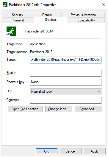
If you experience issues displaying a custom occupant or vehicle avatar, see Fixing Avatar Issues for help troubleshooting.
Pathfinder utilizes many advanced graphics card features in order to provide accelerated and enhanced display of models.
Sometimes these graphics features combined with certain display drivers can cause display issues or crashes on startup. The first step in these cases is to ensure you have the latest operating system updates and graphics drivers installed. If you do and you still have display problems or crashing on startup, you can start Pathfinder in Safe Mode, which disables several graphics features. To start in Safe Mode:
cmd.
Then press Enter.cd "C:\Program Files\Pathfinder 2024".pathfinder -DSafeMode.If you encounter display problems or crashes, please let us know the make/model of your video card and what video driver you are using, even if Safe Mode fixes your issues. That will help us improve the software in future updates.
Pre-defined speed profiles are included in Pathfinder as a convenient starting point Table 18. All Pathfinder models are initialized with a "Default" profile. Additional bundles of profiles are included in the lib/profiles subdirectory of the Pathfinder install location.
| Profile Source | Speed | Speed-Density Relation | Speed Factor Stairs |
|---|---|---|---|
| Default | Constant (1.19 m/s) | SFPE (built-in) | SFPE (built-in) |
| imo_speed_profiles.plib | Uniform Distribution | From Table | Constant |
| fruin_speed_profiles.plib | Normal Distribution | SFPE (built-in) | From Table |
The "Default" profile present in new Pathfinder models is based on data in the SFPE’s Engineering Guide to Human Behavior in Fire (SFPE 2019).
This profile uses a constant speed of 1.19 m/s and relies on Pathfinder’s defaults for speed-density relation and slope-based speed factor on stairs.
The profile bundle imo_speed_profiles.plib is based on data from the IMO’s guidelines (IMO 2007).
This source gives ranges of walking speeds on flat terrain for each of 12 different population groups. This is implemented directly in the Pathfinder profiles as per-profile uniform distributions. The bundle of profiles in Pathfinder includes only the ten population groups that do not correspond to crew members.
A table is given for speed-density relation on flat terrain in terms of "initial specific flow" and a reference "initial speed". These two values were used to create a speed-density factor table shared by all profiles in this set.
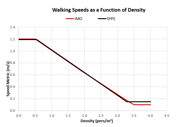
The revised guidelines also define ranges of walking speeds up and down stairs for all population groups. Since Pathfinder requires a speed factor for stairs rather than a range, these values were approximated by calculating a constant scaling factor based on the average of the flat terrain range and the average of the range of speed on stairs.
The profile bundle fruin_speed_profiles.plib is based on data from John Fruin’s Pedestrian Planning and Design (Fruin and Strakosch 1987).
This source describes six population groups based on age and gender, and only gives a single normal distribution of walking speeds that is used for all population groups. This is implemented in Pathfinder by re-using the same normal distribution for the six population groups and an "Average All" aggregate profile.
The built-in SFPE-based speed-density relation is used for all profiles in this set. The built-in SFPE-based speed-density relation differs from the original data primarily in the locations where the min and max walking speeds are clamped. The original data was in terms of an absolute measurement of walking speed across multiple people rather than a value that could be normalized to a specific speed (1.2 m/s) and it went to zero at high densities which is undesirable for simulation because it could cause issues with occupants becoming permanently stuck. The following chart compares the original data to the relation used for this profile in Pathfinder.
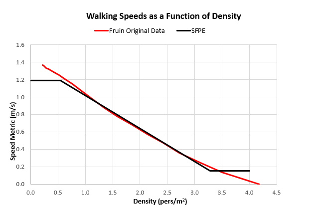
Pedestrian Planning and Design (Fruin and Strakosch 1987) gives stairway speeds for two slopes, identified as an "indoor" 32 degree stair (7" / 11.25") and an "outdoor" 27 degree stair (6" / 12"). Speeds are given for the up direction and the down direction and they are individualized for the six population groups and the aggregate group. These speeds were converted to tables of speed modifier fractions. For each slope and direction, the speed on stairs was converted to a fraction of max speed by dividing by the average of the flat walking speed (1.2 m/s) used by all population groups. This made it possible to create tables of speed modifiers unique to each population group and travel direction that contained two data points. For stairs with slopes more or less than the given 32 and 27 degree stairs, the factor is constant (i.e. not extrapolated).
When Pathfinder imports a custom avatar or animation (see Importing Custom Avatars and Importing Custom Animations), a JSON file is also created for each avatar and animation.
Avatar JSON files are placed in %APPDATA%/Pathfinder/models/md5 and animation JSON files are placed in %APPDATA/Pathfinder/models/anims.
A unified JSON file format is used for both avatars and animations and includes information such as a transformations (e.g. scaling, rotation, and offset), natural speeds for move animations, etc.
One of these files can contain information about the avatar, animations, or both.
An avatar JSON file contains information about a single avatar, including the base avatar file, transformation information, custom animation information, etc.
When Pathfinder imports a custom avatar, it will automatically create this file and place it in %APPDATA%/Pathfinder/models/md5, along with other supporting files, such as the imported FBX or GLB file.
This file can be manually modified in a text editor to fix avatar issues, such as incorrect animations, scaling, orientation, etc. (see Fixing Avatar Issues).
In order to be recognized by Pathfinder and 3D Results, an avatar file must have the following traits.
%PROGRAMDATA%/Pathfinder/models/md5 - shared with all users on the computer.%APPDATA%/Pathfinder/models/md5 - only available to the current user on the computer.
This is the location for imported avatars.An avatar file can optionally contain an anims section. If it does, the listed animations can either be ones that are only available to the file’s avatar or animations that override those in the animation database. For instance, if an avatar appears to be skating when using one of the move animations (see Move Animations), the move animation can be overridden in the avatar’s JSON file to specify a different natural speed than that in the animation database.
The following example illustrates the JSON avatar file format.
In this example, the idle animation specifies a UUID that is not used in any animation database (shipped or custom).
This means that this idle animation would only be available to this avatar.
The move animation, however, shares a UUID with one of the move animations in the shipped animation database (pathfinder_install_folder/lib/models/md5/anims/anim_database.json), indicating that the database move animation is being overridden with this one for this avatar.
{
  "mesh":
  {
    "path": "Ch23_nonPBR.fbx"
  },
  "anims":
  [
    {
      "type": "idle",
      "uuid": "B32615B3-DD16-4D7B-ABDC-7CA79505E626",
      "tags": ["sit", "hands-in-lap"],
      "path": "clips/Sitting Idle.fbx",
      "retargetTo": "other",
      "retargetSource": "meshes/Ch36.fbx"
    },
    {
      "type": "move",
      "uuid": "C15E0D93-BD70-43EF-9C47-E29CBD0691CB",
      "tags": ["upright", "default"],
      "dir": ["forward"],
      "clips":
      [
        {
          "path": "walk1.md5anim",
          "uuid": "98844734-D888-40CB-A9EF-258458498963",
          "frameOffset": 42,
          "naturalSpeed": 0.6,
          "maxSpeed": 1.1,
          "retargetTo": "other",
          "retargetSource": "base_mesh.md5mesh"
        },
        {
          "path": "walk3.md5anim",
          "uuid": "8A069997-851C-4585-AEB9-C76553AAF6E0",
          "frameOffset": 20,
          "naturalSpeed": 1.5,
          "maxSpeed": 1.7,
          "retargetTo": "other",
          "retargetSource": "base_mesh.md5mesh"
        },
        {
          "path": "maleRun.md5anim",
          "uuid": "9FAD15C0-34F5-45A3-876E-F10E9FF2B8C5",
          "frameOffset": 14,
          "naturalSpeed": 2.5,
          "retargetTo": "other",
          "retargetSource": "base_mesh.md5mesh"
        }
      ]
    }
  ]
}The animation JSON file represents a single database animation that can be used with any avatar and contains information about the animation, such as the base animation file, transformation information, movement speeds and directions, etc.
When Pathfinder imports a custom animation, it will automatically create this file and place it in %APPDATA%/Pathfinder/models/anims, along with other supporting files, such as the imported FBX file.
In most cases, these files should not be edited directly; the Pathfinder user interface should be used instead.
However, in some cases, it may be necessary to manually edit in a text editor to fix certain issues, such as unrecognized joint names (see Fixing Avatar Issues).
While nearly identical to the avatar JSON file format, the animation file format has the following key differences:
%PROGRAMDATA%/Pathfinder/models/anims - shared with all users on the computer.%APPDATA%/Pathfinder/models/anims - only available to the current user on the computer.
This is the location for imported avatars.Only a single animation should be specified in the anims section.
The following examples illustrate the animation JSON file format.
The first example shows an idle animation that has a unique UUID across all database animations (those shipped with Pathfinder and custom animations imported using Pathfinder).
As such, it will exist as a unique animation in the database.
{
  "anims":
  [
    {
      "type": "idle",
      "uuid": "B32615B3-DD16-4D7B-ABDC-7CA79505E626",
      "tags": ["sit", "hands-in-lap"],
      "path": "clips/Sitting Idle.fbx",
      "retargetTo": "other",
      "retargetSource": "meshes/Ch36.fbx"
    }
  ]
}
The second example represents a move animation composed of multiple clips.
Unlike in the first example, however, the animation’s UUID (C15E0D93-BD70-43EF-9C47-E29CBD0691CB) matches one of the move animations in the shipped animation database (pathfinder_install_folder/lib/models/md5/anims/anim_database.json).
This indicates that all avatars whose move animation matches the tags default,upright should use this animation instead of the one shipped with Pathfinder.
{
  "anims":
  [
    {
      "type": "move",
      "uuid": "C15E0D93-BD70-43EF-9C47-E29CBD0691CB",
      "tags": ["upright", "default"],
      "dir": ["forward"],
      "clips":
      [
        {
          "path": "walk1.md5anim",
          "uuid": "98844734-D888-40CB-A9EF-258458498963",
          "frameOffset": 42,
          "naturalSpeed": 0.6,
          "maxSpeed": 1.1,
          "retargetTo": "other",
          "retargetSource": "base_mesh.md5mesh"
        },
        {
          "path": "walk3.md5anim",
          "uuid": "8A069997-851C-4585-AEB9-C76553AAF6E0",
          "frameOffset": 20,
          "naturalSpeed": 1.5,
          "maxSpeed": 1.7,
          "retargetTo": "other",
          "retargetSource": "base_mesh.md5mesh"
        },
        {
          "path": "maleRun.md5anim",
          "uuid": "9FAD15C0-34F5-45A3-876E-F10E9FF2B8C5",
          "frameOffset": 14,
          "naturalSpeed": 2.5,
          "retargetTo": "other",
          "retargetSource": "base_mesh.md5mesh"
        }
      ]
    }
  ]
}The following tables list the properties available in the JSON avatar and animation files.
| Property | Type | Default Value | Required? | Description | Example |
|---|---|---|---|---|---|
| mesh | mesh | {} | Yes, if the file represents an avatar. | Links to the avatar file and describes any scaling and other transformation properties. | |
| anims | list of animation | [] | Yes, if the file represents a database animation. Optional if the file represents an avatar. | Lists the animations in the file. | |
| jointNameMapFile | string | "" | no | References an external file containing a joint name map (see Joint Name Map) that should be used for the referenced mesh and all animations in the file.
Ignored if |
The joint name map is in a file called |
| jointNameMap | map | {} | no | Defines joint name mapping (see Joint Name Map) that should be used for the referenced mesh and all animations in the file. | {
"pelvis.5_5":"pelvis",
"L5.6_6":"Spine"
}Maps the file’s unrecognized joint names, |
mesh Properties| Property | Type | Default Value | Required? | Description | Example |
|---|---|---|---|---|---|
| path | string | "" | yes | The relative or absolute path to the avatar file. This can be an FBX, MD5MESH, GLTF, or GLB file. |
Links to the file, |
| uuid | string | "" | No, but recommended | A UUID (universally-unique identifier) that uniquely identifies the mesh. This should be unique across all other avatars. While providing a UUID is recommended, if one is not provided, it will be generated automatically from other mesh properties. |
Assigns the UUID |
| transform | list of transform | [] | no | A list of transform objects to apply to the mesh. The transform objects are combined to form a single transformation as follows:
|
Applies transforms in this order:
|
| importOptions | number | 0 | no | Options that can be used to import the mesh file. The available options are specific to the type of mesh file. | 0 |
| jointNameMapFile | string | "" | no | References an external file containing a joint name map for the mesh.
This overrides any joint name map specified in the root.
Ignored if | See Table 19. |
| jointNameMap | map | {} | no | Defines joint name mapping for the mesh. This overrides any joint name map specified in the root. | See Table 19. |
transform Properties| Property | Type | Default Value | Required? | Description | Example |
|---|---|---|---|---|---|
| translate | array of 3 numbers | [0,0,0] | no | Defines an offset in meters. |
Moves along the |
| rotate | array of 4 numbers | [0,0,1,0] | no | Defines a rotation. The first three values describe the axis (should be normalized), and the fourth value describes the angle in degrees. Rotations are always performed CCW about the axis. |
Rotates about the |
| scale | number | 1 | no | Defines scaling. All scaling is performed uniformly about all axes. |
Scales |
animation Properties| Property | Type | Default Value | Required? | Description | Example |
|---|---|---|---|---|---|
| type | string | "idle" | yes | Describes the type of animation. Must be one of the following values:
|
This is an idle animation (used when an occupant is stationary). |
| tags | list of string | [] | yes | A list of tags that can be used in Pathfinder to identify the animation (see Animation Tab). |
Associates the animation with all combinations of
|
The following animation properties are also available if animation:type is "idle".
animation Properties (idle-only)| Property | Type | Default Value | Required? | Description | Example |
|---|---|---|---|---|---|
| path | string | "" | yes, if type="idle" | The path to the animation file.
This may be an |
Links to the file, |
| uuid | string | "" | No, but recommended | A UUID (universally-unique identifier) that identifies the animation. If the UUID is unique across all other animations, the animation exists on its own. However, if the UUID matches one in the animation database that is provided with Pathfinder, this animation overrides that in the database. While providing a UUID is recommended, if one is not provided, it will be generated automatically from other animation properties. |
Assigns the UUID |
| frameOffset | number | 0 | no | Remaps the specified frame as frame |
Assigns the 5th frame in the animation file as the first frame of the animation. |
| transform | list of transform | [] | no | Uses the same format as in the mesh section. | |
| retargetTo | string | "" | no | Indicates whether the animation needs to be retargeted. The following values are accepted:
|
|
| retargetSource | string | "" | Yes, if retargetTo is "other" | Specifies the path to the mesh for which the animation was created if |
The animation was created for |
| idlePlayback | string | "randomize" | no | Defines how an idle animation will be played. Can be one of the following values:
|
|
| jointNameMapFile | string | "" | no | References an external file containing a joint name map for the animation.
This overrides any joint name map specified in the root.
Ignored if | See Table 19. |
| jointNameMap | map | {} | no | Defines joint name mapping for the animation. This overrides any joint name map specified in the root. | See Table 19. |
The following animation properties are also available if animation:type is "move" or "pivot".
animation Properties (move-only)| Property | Type | Default Value | Required? | Description | Example |
|---|---|---|---|---|---|
| uuid | string | "" | No, but recommended | A UUID (universally-unique identifier) that identifies the move animation. If the UUID is unique across all other animations, the animation exists on its own. However, if the UUID matches one in the animation database that is provided with Pathfinder, this animation overrides that in the database. While providing a UUID is recommended, if one is not provided, it will be generated automatically from other animation properties. |
|
| dir | list of string | [] | yes (at least 1 must be defined) | Defines the natural movement direction of the animation, relative to the avatar’s facing direction. This can be a combination of the following:
|
Defines an animation that moves the occupant |
| clips | list of move_clip | [] | yes (at least 1 must be defined) | Defines a list of individual animation clips that make up a composite animation in the specified direction.
Each | See the JSON examples above (see Example Animation JSON File). |
move_clip Properties| Property | Type | Default Value | Required? | Description | Example |
|---|---|---|---|---|---|
| path uuid frameOffset retargetTo retargetSource jointNameMapFile jointNameMap | See the | ||||
| naturalSpeed | number | 0 | no | The natural movement speed in |
The animation will be played back at |
| maxSpeed | number | +infinity | Yes, if this is not the last move animation clip. | The maximum occupant speed in |
The animation will only be used if the occupant’s speed is ⇐ |
If some or all of an occupant avatar’s body parts do not move during animations, this may be because either the avatar file or animation file uses unknown joint names for the skinning hierarchy. To determine if this is the case, perform the following:
The command prompt will display lines such as the following if there are unknown joint names:
[avatar.fbx] Could not determine joint type for joint, "L5.6_6"
[avatar.fbx] Could not determine joint type for joint, "l_hip_n.87_87"
[avatar.fbx] Could not determine joint type for joint, "l_knee_n.88_88"
If this is the case, these errors can be fixed by supplying a joint name map.
There are two ways this can be accomplished:
JSON file (depending on which file caused the errors), specify the joint name mapping using the jointNameMap property.
See Table 19.
This may be useful if the name map only needs to be defined once.JSON file, specify a joint name map file using the jointNameMapFile property.
This may be useful if the name map needs to be used in several places.
It will require creating a name map file as follows:For each of the above errors, add a line to the file in the format, unknown_name=known_name, where unknown_name is the name printed to the command prompt above, and known_name is one of the known joint names as listed in Known Joint Names.
If an unknown joint has no equivalant in the known list (e.g. the avatar has an extra spine joint), the mapping can be omitted from the joint name map file. In this case, the unknown joint will rotate to match its parent joint.
jointNameMapFile property where appropriate.The following example is a joint name map file that would fix the errors in the above example:
L5.6_6=Spine
l_hip_n.87_87=L Thigh
l_knee_n.88_88=L Calf
In this example, L5.6_6 is the unknown name of the joint in the referenced file, and Spine is the known joint name.
The following is one set of known joint names that can be used as known_name in the joint name map file.
Unless indicated with # or a blank line, each joint is a direct parent of the joint on the next line in the list.
Either Bip or Pelvis can be the root node.
Bip
Pelvis
Spine
# Spine splits to `Spine1`, `R Thigh`, and `L Thigh`

Spine1
Spine2
Spine3
Neck
# Neck splits to `Head`, `R Clavicle`, and `L Clavicle`

Head
HeadNub

R Thigh
R Calf
R Foot
R Toe0
R Toe0Nub

R Clavicle
R UpperArm
R Forearm
R Hand
# R Hand connects to `R Finger4`, `R Finger3`, `R Finger2`, `R Finger1`, and `R Finger0`

R Finger4
R Finger41
R Finger42
R Finger4Nub

R Finger3
R Finger31
R Finger32
R Finger3Nub

R Finger2
R Finger21
R Finger22
R Finger2Nub

R Finger1
R Finger11
R Finger12
R Finger1Nub

R Finger0
R Finger01
R Finger02
R Finger0Nub

L Thigh
L Calf
L Foot
L Toe0
L Toe0Nub

L Clavicle
L UpperArm
L Forearm
L Hand
# L Hand connects to `L Finger4`, `L Finger3`, `L Finger2`, `L Finger1`, and `L Finger0`

L Finger4
L Finger41
L Finger42
L Finger4Nub

L Finger3
L Finger31
L Finger32
L Finger3Nub

L Finger2
L Finger21
L Finger22
L Finger2Nub

L Finger1
L Finger11
L Finger12
L Finger1Nub

L Finger0
L Finger01
L Finger02
L Finger0NubPathfinder Technical Reference. n.d. 403 Poyntz Avenue, Suite B, Manhattan, KS 66502, USA: Thunderhead Engineering. https://support.thunderheadeng.com/docs/pathfinder/latest/technical-reference-manual/.
Pathfinder Verification and Validation. n.d. 403 Poyntz Avenue, Suite B, Manhattan, KS 66502, USA: Thunderhead Engineering. https://support.thunderheadeng.com/docs/pathfinder/latest/verification-validation/.
Pathfinder Results User Manual. n.d. 403 Poyntz Avenue, Suite B, Manhattan, KS 66502, USA: Thunderhead Engineering. https://support.thunderheadeng.com/docs/pathfinder/latest/results-user-manual/.
Bukowski, Richard W., and Fang Li. 2010. “Using Elevator In Fires.” Consulting - Specifying Engineer, July.
Fridolf, Karl, Enrico Ronchi, Daniel Nilsson, and Håkan Frantzich. 2019. “The Representation of Evacuation Movement in Smoke- Filled Underground Transportation Systems.” Tunnelling and Underground Space Technology 90 (April): 28–41. https://doi.org/10.1016/j.tust.2019.04.016.
Fruin, J.J., and G.R. Strakosch. 1987. Pedestrian Planning and Design. Elevator World. https://books.google.com/books?id=vrckAQAAMAAJ.
IBM. n.d. “Default Swing Key Bindings.” Accessed November 18, 2019. https://ibm.co/2O58h5A.
IMO. 2007. “IMO Guidelines for Evacuation Analysis for New and Existing Passenger Ships.” 4 Albert Embankment, London, Great Britain: International Maritime Organization.
Pheasant, Stephen, and Christine M. Haslegrave. 2005. Bodyspace: Anthropometry, Ergonomics and the Design of Work. 3rd ed. CRC Press. https://books.google.com/books?id=vrckAQAAMAAJ.
SFPE. 2019. SFPE Guide to Human Behavior in Fire. 2nd ed. Springer International Publishing. https://www.springer.com/gp/book/9783319946962.
Still, G. Keith. 2000. “Crowd Dynamics.” PhD thesis, University of Warwick. http://gkstill.com/Support/Links/Documents/2000_still.pdf.